Sign In
Upload
Manuals
Brands
Mercedes-Benz Manuals
Engine
OM 471
Mercedes-Benz OM 471 Manuals
Manuals and User Guides for Mercedes-Benz OM 471. We have
1
Mercedes-Benz OM 471 manual available for free PDF download: Introduction Into Service Manual
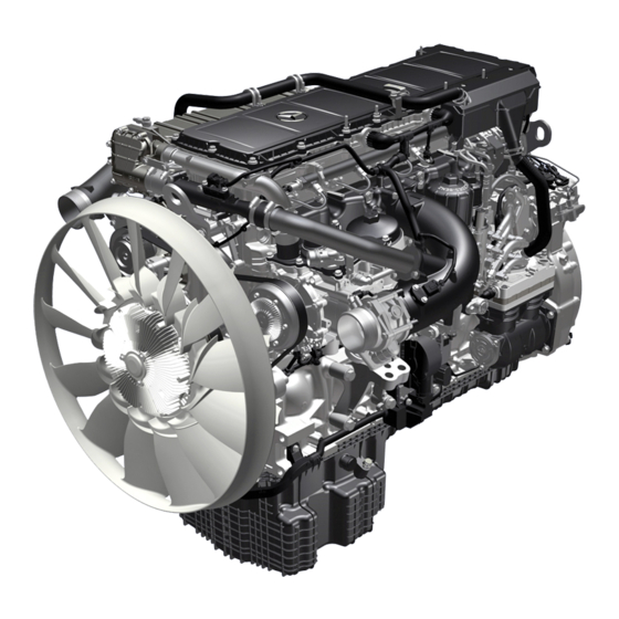
Mercedes-Benz OM 471 Introduction Into Service Manual (226 pages)
Introduction of engine OM 471 and exhaust aftertreatment
Brand:
Mercedes-Benz
| Category:
Engine
| Size: 21.25 MB
Table of Contents
Table of Contents
5
Overview of New Features
13
Engine
13
Technical Data of Diesel Engine OM 471
14
Descriptions
15
As>Built Configuration
15
Cylinder Head Cover, As>Built Configuration
15
Cylinder Head, As>Built Configuration
16
Tightening Procedure for Cylinder Head
16
Cooling Levers
20
Cooling
20
Cylinder Head Gasket, As>Built Configuration
21
Upper Side of the Cylinder Head Seal
21
Crankcase As>Built Configuration
22
Crankcase from Above, Shown with Oil Ducts
22
Crankcase from Below, Shown with Oil Ducts
23
Connecting Rod, As>Built Configuration
24
Piston, As>Built Configuration
25
Protecting the Contact Surfaces
26
Crankshaft, As>Built Configuration
26
Valve Control; As>Built Configuration
27
Valve Control Overall
27
Valve Control on the Exhaust Side
28
Design of the Exhaust Rocker Arm Spindle
28
Design of the Rocker Arm
29
Exhaust Valve Control for a Deactivated Engine Brake
29
Exhaust Valve Control for an Activated Engine Brake
30
Valve Control on the Inlet Side
30
Design of the Intake Rocker Arm Spindle
31
Design of the Intake Rocker Arm
31
Exhaust Valve Control
31
Gear Drive, As>Built Configuration
32
Torque Curve
33
Camshaft, As>Built Configuration
34
Belt Drive, As>Built Configuration
35
2>Belt Drive (Fan Raised)
35
3>Belt Drive (Fan on Crankshaft)
36
Function Descriptions
37
Crankcase Ventilation System Function
37
Forced Induction, Function
38
Boost Pressure Control (Via Wastegate)
39
Turbocharger Protection Function
39
Charging, Function
40
Engine Management, Function
40
Functions
41
Engine Management, Overall Network
41
Response in the Event of Drive Train CAN (CAN 4) Malfunction
43
Response When Camshaft Position Sensor (B601) Fails
43
Response When Crankshaft Position Sensor (B600) Fails
43
Response When a Temperature Sensor Fails
44
Response When an Exhaust Gas Recirculation (EGR) Component Fails
44
Response When Engine Management (MCM) Control Unit (A4) Fails
44
Start Procedure, Function
45
Requirements
45
Determination of the Engine Speed and
46
Crankshaft Angle, Function
46
Determination of the Compression Stroke at
46
Idle Speed Control, Function
47
Altitude Correction
48
Smoke Limitation
48
Smooth Running Control
48
Working Speed Control, Function
49
General Information
49
Regulation of the Working Speed
49
Changing the Working Speed
50
Driving, Function
51
Engine Shutoff Procedure, Function
53
Determination of the Engine Speed and Crankshaft Angle, Function
56
Determination of the Compression Stroke at Cylinder 1, Function
57
Determination of the Coolant Temperature, Function
58
Determination of Air Mass, Function
59
Determination of the Fuel Temperature, Function
60
Function of the Specified Engine Torque Calculation
61
Engine Brake, Function
63
Overview of Components of Valve Timing
63
Engine Brake Deactivated
64
Performance Feature of a Standard and High Performance System
68
Code (M5U) Engine Brake, Standard System
68
Code (M5V) Engine Brake, High Performance System
68
Exhaust Gas Recirculation, Function
69
Networking of the Electrical Components
69
Exhaust Aftertreatment, Function
71
New Diesel Engine Generation
71
The Emissions Standard Euro V, EEV
71
Function of the EATS (Overall System)
73
Reduction of Nox in the SCR Catalytic Converter
73
Adblue“ Line System
74
Adblue“ Heater
74
Function of Adblue“ Heating by Coolant
74
Function of Adblue“ Heating by an Electrical Heater
74
Euro VI Emissions Standard
76
System Overview
77
Electronic Networking
78
Networking of Control Units
79
Function of Exhaust Aftertreatment System (Overall System)
79
Adblue“/Coolant Line System
80
Exhaust Aftertreatment Overall Network
82
Engine Oil Circuit, Function
83
Engine Oil Circuit Schematic
85
Coolant Circuit, Function
86
Engine Cooling Circuit
86
Heating Circuit
87
(B3H) Secondary Water Retarder
87
Coolant Circuit Schematic
89
Engine Cooling Thermal Management, Function
90
Electromagnetic Coolant Pump Control
90
Electromagnetic Fan Clutch Control, Function
91
Cooling Air Control, Function (with Code (M7K) Radiator Shutters)
91
Engine Cooling Thermal Management Overall Network
93
Fuel Supply, Function
94
Fuel Low Pressure Circuit
95
Fuel High>Pressure Circuit
95
Fuel Low Pressure Circuit Function
96
Fuel High Pressure Circuit Function
103
Central Gateway Control Unit (CGW), Component Description
104
Routing Data
104
Bus Termination Resistors
104
Control Unit Monitoring
104
Component Description Drive Control (CPC) Control Unit
105
Component Description for Engine Management (MCM) Control Unit
106
System Components
107
Exhaust Gas Recirculation (EGR)
107
IC Control Unit (ICUC) (A1)
107
Fan Control
107
Electronic Brake Control Control Unit (EBS), Component Description
108
Battery Disconnect Switch Control Unit, Component Description
110
Radiator Shutters, Component Description
112
Proximity Control Assist
112
EATU Output Nox Sensor, Component Description
113
Exhaust Aftertreatment Unit Outlet Nox Sensor, Component Description
115
Pump Module, Component Description
118
Exhaust Aftertreatment (ACM) Control Unit, Component Description
120
Adblue Metering Device, Component Description
124
EATU Input Nox Sensor, Component Description
126
Exhaust Aftertreatment Unit Inlet Nox Sensor, Component Description
128
Auxiliary Heater Unit, Component Description
131
Auxiliary Heater Coolant Circulation Pump, Component Description
133
Travel and Speed Sensor, Component Description
134
Component Description for Accelerator Pedal Sensor
137
Adblue“ Fill Level Sensor/Temperature Sensor, Component Description
145
Determination of the Fill Level
146
Determination of Temperature
146
Coolant Pressure Control Sensor, Component Description
147
Component Description for Crankshaft Position Sensor
148
Component Description for Camshaft Position Sensor
149
Component Description for Fuel Temperature Sensor
150
Oil Pressure Sensor, Description of Components
151
Component Description for Engine Oil Fill Level Sensor
152
Component Description for Exhaust Coolant Temperature Sensor
153
Component Description for Intake Coolant Temperature Sensor
154
Component Description for Turbine Wheel Rpm Sensor
156
Component Description for Temperature Sensor Downstream of Air Filter
157
Component Description for EGR Differential Pressure Sensor
159
Component Description for Rail Pressure Sensor
160
Diesel Fuel Metering Device, Component Description
161
Fuel Filter Module Pressure Sensor, Component Description
162
Component Description for Coolant Pump
163
Residual Heat Pump, Component Description
165
Tachograph (TCO) Component Description
166
Electronic Ignition Lock (EIS), Component Description
167
EMERGENCY off Switch, Component Description
168
Shown on Left>Hand Drive Vehicle
168
Frame EMERGENCY off Switch, Component Description
169
Engine Start and Engine Stop Button, Component Description
170
Heating Shutoff Valve, Component Description
171
Coolant Pressure Control Solenoid Valve, Component Description
172
Component Description for Fuel Injectors
173
Arrow Injector Quantity Compensation Code
174
Injection Without a Pressure Booster (4)
174
Injection with a Pressure Booster (4)
175
Graphic Presentation of the Injection Process
175
Component Description for the Electromagnetic Viscous Coupling
177
Thermal Protection Function
178
Component Description for Exhaust Gas Recirculation Controller
179
Exhaust Gas Recirculation Rate Control
180
Influence on the Engine Braking System
180
Component Description for Engine Brake Solenoid Valve
181
Activation of the Engine Brake
182
Deactivation of the Engine Brake
182
Adblue“ Heater Coolant Solenoid Valve, Component Description
183
Component Description for Boost Pressure Regulator
184
Component Description for Quantity Control Valve
185
Component Description for Oil Separator
186
Component Description for Fuel System High Pressure Pump
187
Component Description for Pressure Limiting Valve
188
Component Description for Turbocharger
189
Component Description for Exhaust Gas Recirculation Cooler
190
Component Description for Adblue Tank
191
Component Description for Oil Pump
192
Oil/Coolant Module, Component Description
194
Oil Thermostat, Component Description
196
Component Description for Oil/Water Heat Exchanger
197
Component Description for Coolant Thermostat
198
Bypass Mode
199
Mixed Mode
199
Cooler Mode
199
Retarder, Component Description
200
Sectional View of Secondary Water Retarder
201
Relief Valve
201
Valve Block
201
Actuator
202
Side Channel Pump
202
Twisted Teeth
202
Slide Ring Seal
203
Evaporation Tray
203
Retarder Shaft
203
Shutoff Pressure Line, Feed
204
Rotor
204
Stator
204
Coolant Temperature Sensor (B933)
205
Component Description for Fuel Pump
206
Component Description for Fuel Cooler
207
Component Description for Fuel Filter Module
208
Fuel Prefilter
209
Water Separator and Fuel Filter
210
Diesel Oxidation Catalytic Converter, Component Description
211
Component Description for SCR Catalytic Converter
212
Exhaust Aftertreatment Unit, Component Description
216
Location of Sensors
217
Regeneration
222
Passive Regeneration
222
Active Regeneration
222
Nozzle Unit for DPF Regeneration, Component Description
223
Heating System Heat Exchanger, Component Description
224
Advertisement
Advertisement
Related Products
Mercedes-Benz OM 457 LA
Mercedes-Benz OM 460 LA
Mercedes-Benz OM 470 Euro VI
Mercedes-Benz OM 471 Euro VI
Mercedes-Benz OM 473 Euro VI
Mercedes-Benz OM 904-926 LA BlueTec
Mercedes-Benz OM 651
Mercedes-Benz OM 904 LA
Mercedes-Benz OM 906 LA
Mercedes-Benz OM602
Mercedes-Benz Categories
Automobile
Automobile Accessories
Car Receiver
Car Stereo System
Car Video System
More Mercedes-Benz Manuals
Login
Sign In
OR
Sign in with Facebook
Sign in with Google
Upload manual
Upload from disk
Upload from URL