
Related Manuals for Mercedes-Benz V12 Biturbo M 279 AMG


Summary of Contents for Mercedes-Benz V12 Biturbo M 279 AMG
- Page 1 Introduction of the New V12 Biturbo Engine M 279 AMG Introduction into Service Manual – This printout will not be recorded by the update service. Status: 06 / 2012 –...
- Page 2 Mercedes-Benz Service Introduction of the New V12 Biturbo Engine M 279 AMG Daimler AG · Technical Information and Workshop Equipment (GSP/OR) · D-70546 Stuttgart – This printout will not be recorded by the update service. Status: 06 / 2012 –...
- Page 3 Information and copyright Product Portfolio You can also find comprehensive information on our complete product port- folio in our Internet portal: Link: http://aftersales.mercedes-benz.com Questions and suggestions If you have any questions or suggestions concerning this product, please write to us.
- Page 4 Contents Preface Overview Highlights Engine data comparison: M 275 AMG - M 279 AMG Engine views Maintenance ASSYST Mechanical components Crankcase Oil pan Crank assembly Cylinder head Belt drive Combustion Charging Fuel system Exhaust system Introduction of the New V12 Biturbo Engine, M 279 AMG –...
- Page 5 Contents Cooling and lubrication Engine cooling Turbocharger cooling Charge air cooling Engine lubrication Electrical and electronic systems Engine control Ignition system On-board diagnosis Special tools Electrical/mechanical components Annex Abbreviations Index Introduction of the New V12 Biturbo Engine, M 279 AMG –...
-
Page 6: Preface
We will publicize modifications and new features assumed that the reader is already familiar with the in the relevant WIS documents. The information engines in the various Mercedes-Benz models presented in this Introduction into Service Manual currently on the market. -
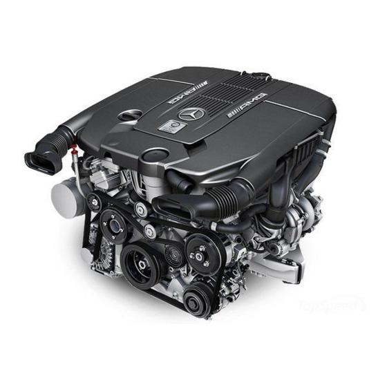
Page 7: Highlights
Highlights In September 2012 Mercedes-AMG will introduce The main features of the V12 biturbo engine the new 12-cylinder V-engine M 279 AMG in the M 279 AMG in brief: new SL-Class (model series 231). • Two modified turbochargers with air/water This advanced V12 engine with the model designa- intercooling and wastegate valve tion M 279 focuses rigorously on performance and... -
Page 8: Engine Data Comparison: M 275 Amg - M 279 Amg
Engine data comparison: M 275 AMG - M 279 AMG M 275 KE60 LA AMG M 279 KE60 LA AMG M 275.981 M 279.981 Cylinder configuration/angle V12/60° Rated output at engine speed 4800-5100 4800-5400 Rated torque 1000 1000 at engine speed 2000-4000 2300-4300 Displacement... - Page 9 Engine data comparison: M 275 AMG - M 279 AMG P01.00-3353-00 Torque and power curve, M 275 AMG and M 279 AMG M Torque P Power n Engine speed Introduction of the New V12 Biturbo Engine, M 279 AMG – This printout will not be recorded by the update service. Status: 06 / 2012 –...
-
Page 10: Engine Views
Engine views P01.10-3111-00 View of engine from above Air filter housing, right cylinder bank B28/4 Pressure sensor downstream of air filter, Charge air cooler, right cylinder bank left cylinder bank Charge air cooler, left cylinder bank B28/5 Pressure sensor downstream of air filter, Air filter housing, left cylinder bank right cylinder bank Introduction of the New V12 Biturbo Engine, M 279 AMG... - Page 11 Engine views P01.10-3112-00 View of engine from above Refrigerant compressor T1/7 Cylinder 7 ignition coil B11/4 Coolant temperature sensor T1/8 Cylinder 8 ignition coil Alternator T1/9 Cylinder 9 ignition coil M16/6 Throttle valve actuator T1/10 Cylinder 10 ignition coil T1/1 Cylinder 1 ignition coil T1/11 Cylinder 11 ignition coil...
- Page 12 Engine views P01.10-3113-00 View of engine from above Left air shutoff valve Y62/4 Cylinder 4 injection valve Right air shutoff valve Y62/5 Cylinder 5 injection valve Y62/6 Cylinder 6 injection valve B17/8 Charge air temperature sensor Y62/7 Cylinder 7 injection valve B28/7 Pressure sensor downstream of throttle valve Y62/8 Cylinder 8 injection valve...
- Page 13 Engine views P01.10-3114-00 View of engine from rear B6/1 Camshaft Hall sensor Crankshaft Hall sensor 28/6 Pressure sensor upstream of throttle valve Starter Introduction of the New V12 Biturbo Engine, M 279 AMG – This printout will not be recorded by the update service. Status: 06 / 2012 –...
- Page 14 Engine views P01.10-3115-00 View of engine from left 1 Blow-off valve A16/1 Knock sensor 1 2 Left turbocharger A16/2 Knock sensor 2 Introduction of the New V12 Biturbo Engine, M 279 AMG – This printout will not be recorded by the update service. Status: 06 / 2012 –...
- Page 15 Engine views P01.10-3116-00 View of engine from right 1 Blow-off valve A16/3 Knock sensor 3 2 Right turbocharger A16/4 Knock sensor 4 Introduction of the New V12 Biturbo Engine, M 279 AMG – This printout will not be recorded by the update service. Status: 06 / 2012 –...
-
Page 16: Assyst
ASSYST New technical features The new engine M 279 AMG is being introduced in The oil change interval for the 7-speed automatic the SL-Class. The maintenance intervals remain the transmission AMG SPEEDSHIFT PLUS 7G-TRONIC same as for its predecessor engine M 275. is "every 125,000 km/5 years". -
Page 17: Crankcase
Crankcase A die-cast aluminum crankcase with Silitec cylinder i Note liners is used in the new M 279 AMG. The engine number is impressed in the center of The bore and cylinder spacing of the M 275 AMG the bottom of the crankcase (bedplate). have been preserved. - Page 18 Crankcase Ventilation The engine crankcase is ventilated via a centrifugal Check valves in the partial-load vent line and in the oil separator driven by the left camshaft. An integral full-load vent line ensure that the gases flow in the pressure regulating valve provides the necessary correct direction out of the crankcase.
- Page 19 Crankcase CARB – California Air Resources Board CARB is the clean-air agency of the state of Cali- Engine M 279 AMG satisfies these requirements fornia, which proposes legislation aimed at with the following measures: preventing air pollution. • The partial-load vent line (items 3 and 4) is According to the guidelines of this authority, safeguarded by the OBD which detects any published in the California Code of Regulation...
- Page 20 Crankcase Vapors loaded with oil mist coming from the crank- i Note case enter the centrifuge, which rotates at the Even with such efficient oil separation, minute same speed as the camshaft. Here the vapors are residual quantities of oil mist pass through the made to rotate, and the oil particles separate from separator.
-
Page 21: Oil Pan
Oil pan The oil pan in model series 231 is a rear sump. The The oil sensor for measuring the oil level, tempera- upper and lower sections of the oil pan are ture and quality is located in the rear of the oil aluminum sand castings. -
Page 22: Crank Assembly
Crank assembly Crankshaft Connecting rods The crankshaft has been modified with regard to The connecting rods are forged from a high- the threaded connection of the flywheel. strength steel alloy and are therefore capable of withstanding the high loads caused by the turbo- With its precision-turned counterweights the crank- charging with no increase in weight. -
Page 23: Cylinder Head
Cylinder head Each cylinder head has an overhead camshaft i Note (OHC). The camshafts are forged. They consist of an In the M 279 AMG aluminum bolts are used on the internal high-pressure formed steel tube with joined two valve covers and on the charge air distributor. cams. - Page 24 Cylinder head Valve assembly The valve timing with hydraulic valve clearance The left camshaft drives the centrifugal oil sepa- compensation is performed by roller-type cam rator of the crankcase ventilation system. followers. The crankshaft sprocket is lined with rubber to The valve springs are identical on the intake and reduce noise.
-
Page 25: Belt Drive
Belt drive The belt drive is a single-belt system and drives the Due to the high dynamic requirements of the AMG ancillaries coolant pump, alternator, ABC pump and SPEEDSHIFT PLUS 7G-TRONIC with very short refrigerant compressor. response times, the belt pulley of the alternator is fitted with a freewheel. -
Page 26: Charging
Charging Turbocharging The volumetric efficiency of the cylinders is According to the on/off ratio either some or all of improved as a result of charging. This increases the the boost pressure from the charge air cooler of the torque and the power output of the engine. right cylinder bank acts in the vacuum cells. - Page 27 Charging P09.00-2125-00 Function schematic of forced induction B17/8 Charge air temperature sensor Pressure sensors downstream of air filter, signal B28/4 Pressure sensor downstream of air filter, Boost pressure, signal left cylinder bank Intake manifold pressure, signal B28/5 Pressure sensor downstream of air filter, Accelerator pedal sensor, signal right cylinder bank Engine speed, signal...
- Page 28 Charging Turbocharger The turbochargers are made of cast steel. The The high rotational speed of the compressor impel- turbine housings are integrated in the exhaust lers and the resultant high volumetric flow rates manifolds. The bearing housings are cooled by the compress the air in the charge air pipes.
- Page 29 Charging P09.40-2422-00 Flow pattern of intake air/charge air B28/4 Pressure sensor downstream of air filter, 1 Left turbocharger left cylinder bank 2 Right turbocharger B28/5 Pressure sensor downstream of air filter, 3 Charge air cooler, left cylinder bank right cylinder bank 4 Charge air cooler, right cylinder bank B28/6 Pressure sensor upstream of throttle valve B28/7 Pressure sensor downstream of throttle valve...
- Page 30 Charging Bypass air Due to the inertia of the shafts, compressor impel- When the bypass air switchover valve is not actu- lers and turbine wheels, the turbochargers rotate ated (in charging mode), the diaphragm chambers slightly behind at the start of deceleration and of the blow-off valves are connected with the continue to produce charge pressure against the charge air distributor.
- Page 31 Charging P09.40-2423-00 Bypass air 1 Intake manifold A Vacuum from bypass air switchover valve to 2 Vacuum reservoir blow-off valve 3 Check valve (vacuum) B Vacuum to air pump 1 switchover valve 4 Blow-off valve and air pump 2 switchover valve 5 Left turbocharger C Bypass air test connection 6 Right turbocharger...
-
Page 32: Fuel System
Fuel system Fuel supply Fuel feed The fuel supply system provides the fuel injection The fuel pump draws the fuel through the fuel valves with a sufficient quantity of filtered fuel from strainer at the bottom of the fuel feed module and the fuel tank as a sufficient pressure under all oper- pumps it through the fuel filter with fuel pressure ating conditions. -
Page 33: Fuel Filter
Fuel system Fuel pressure regulator Purging The fuel pressure regulator limits the fuel pressure Fuel vapors must not be allowed to escape into the by adjusting the fuel return quantity. When the set atmosphere when the fuel tank is vented. fuel pressure is exceeded, the diaphragm in the fuel The fuel vapors are stored in the activated charcoal pressure regulator is pressed against the... - Page 34 Fuel system P47.10-2634-00 Fuel tank ECE version Fuel tank fill level sensor USA version fuel level indicator Fuel filler neck B4/3 Fuel tank pressure sensor (USA only) Fuel feed module B4/7 Fuel pressure sensor 55/2 Fuel filter Fuel pump Fuel tank N118 Fuel system control unit 75/1 Refueling, limiting and vent valve (USA only)
- Page 35 Fuel system Injection valves The injection valves spray a calculated quantity of finely atomized fuel into the intake port of the relevant cylinder at a certain point in time. When the solenoid coil is energized, the nozzle needle is raised approx. 0.1 mm via the solenoid armature against the force of the coil spring.
- Page 36 Fuel system Injection control The engine is allocated the necessary fuel quantity Partial-load operation by the ME-SFI control unit. In partial-load operation with the engine warm, the The ME-SFI control unit uses a characteristics map ME-SFI control unit calculates the actuation time of to calculated the required injection period on the the injection valves according to the lambda control basis of the following sensors and signals:...
-
Page 37: Exhaust System
Exhaust system Exhaust treatment Secondary air injection The task of the exhaust treatment system is to Secondary air injection is a measure for ensuring reduce exhaust emissions. that emissions limits are complied with during (cold) engine starts. To do so, the catalytic converters, for example, must be quickly brought up to operating Function requirements for secondary air injection temperature so that exhaust emissions during cold... - Page 38 Exhaust system For secondary air injection the air pump 1 and 2 i Note switchover valves and the electric air pump are Secondary air injection may be enabled for actuated simultaneously by the ME-SFI control unit diagnosis with Xentry Diagnostics for max. 120 s for max.
- Page 39 Exhaust system Secondary air pressure sensor Diagnosis of the secondary air injection must occur As soon as the coolant temperature has exceeded before the oxygen sensors are ready to operate. a value of 40 °C, the secondary air system and the pressure-based diagnosis function are inoperative To accomplish this, a pressure-based diagnosis in the following driving situations:...
- Page 40 Exhaust system Air shutoff valves When air injection is actuated, the air shutoff valves open the path for the injected air. With air injection switched off, they prevent exhaust gas stream from drawing air into the exhaust ports. When air injection is enabled, the left air shutoff valve is actuated via the air pump 1 switchover valve and the right air shutoff valve via the air pump 2 switchover valve using vacuum from the intake...
- Page 41 Exhaust system Exhaust system The task of the exhaust treatment system is to The twin-pipe exhaust system consists of: reduce exhaust emissions: • One firewall catalytic converter with two • Nitrogen oxides (NOx) "monoliths" for each pipe • Hydrocarbon (HC) •...
-
Page 42: Engine Cooling
Engine cooling Coolant temperature regulation In order to guarantee the maximum engine power, the engine and turbochargers must be properly The coolant temperature is regulated by the ME-SFI cooled. control unit on the basis of the following sensors The engine oil cooler (oil/air heat exchanger) is and signals: located in the center behind the front spoiler. - Page 43 Engine cooling Fan control Overheating protection The ME-SFI control unit actuates the engine and air The overheating protection function provides conditioning electric suction fan with integrated protection against engine damage in the event of control. The target fan speed is specified by the ME- thermal overload and prevents overheating damage SFI control unit by means of a pulse width modu- to the catalytic converters.
-
Page 44: Introduction Of The New V12 Biturbo Engine, M 279 Amg B
Engine cooling Introduction of the New V12 Biturbo Engine, M 279 AMG – This printout will not be recorded by the update service. Status: 06 / 2012 –... - Page 45 Engine cooling Introduction of the New V12 Biturbo Engine, M 279 AMG – This printout will not be recorded by the update service. Status: 06 / 2012 –...
- Page 46 Engine cooling P20.00-2447-00 Coolant circuit (schematic) 1 Radiator B11/4 Coolant temperature sensor 2 Low-temperature cooler M4/7 Engine and air conditioning electric suction fan 3 Coolant pump with integrated control 4 Coolant thermostat Charge air cooler circulation pump 5 Expansion reservoir Coolant level indicator switch 6 Low-temperature circuit expansion reservoir 7 Right cylinder bank...
-
Page 47: Turbocharger Cooling
Turbocharger cooling Turbocharger cooling i Thermosiphon principle Due to the difference in density between warm Coolant flows through the bearing housing of the and cold water, the warm (lighter) water experi- turbochargers. The coolant flows to each of the ences lift and rises upwards. turbochargers via a different connection in the cylinder crankcase, and passes through the bearing housings from bottom to top. -
Page 48: Charge Air Cooling
Charge air cooling The cooled sir downstream of the charge air coolers One charge air cooler is installed for each cylinder has a higher density. This increases the cylinder bank. Both charge air coolers are connected to the charge and thus the engine power. In addition, the low-temperature cooling circuit with low-tempera- tendency to knock is decreased and the lower ture cooler, expansion reservoir and charge air... - Page 49 Charge air cooling When the charge air temperature drops below If the charge air temperature exceeds 45 °C, the 35 °C, the coolant circulation pump is switched off charge air cooler circulation pump is actuated by again. the ME-SFI control unit via the engine coolant circu- lation pump relay.
-
Page 50: Engine Lubrication
Engine lubrication Engine oil pump The engine oil pump is a compound pump with two suction levels for the returning oil from the turbo- chargers. P18.10-2202-00 Engine oil pump 4 Delivery stage 2 1 Pressure connection 5 Intake connection 2 Pressure regulating valve 3 Delivery stage 1 Introduction of the New V12 Biturbo Engine, M 279 AMG –... -
Page 51: Oil Circuit
Engine lubrication Oil circuit P18.00-2328-00 Oil circuit diagram, M 279 AMG 1 Oil pan A Oil filter 2 Timing case cover B Engine oil cooler (oil/air heat exchanger) 3 Cylinder crankcase C Oil pump 4 Left cylinder head D Valve compensating elements 5 Right cylinder head E Oil spray nozzles 6 Left turbocharger... - Page 52 Engine lubrication Turbocharger The shaft of the turbocharger with the turbine wheel The oil feed and drain routes for lubricating the and compressor impeller is supplied with oil via the turbocharger are designed not to interfere with the engine's oil circuit. The oil flows in the opposite lubricating oil circuit of the engine.
-
Page 53: Engine Control
Engine control ME-SFI [ME] control unit Task The ME-SFI control unit is located on the left in the The ME-SFI control unit performs the following rear of the engine compartment in the control unit tasks: box on the driver side. •... - Page 54 Engine control Engine control ME 17.7.8 The gasoline injection and ignition system forms The basic functions include: the engine control system "ME17.7.8" in the elec- • Control unit diagnosis trical group with the sensors and actuators of • Fault memory engine 279 KE (port injection).
- Page 55 Engine control The engine system comprises the following The ignition system comprises: functions: • Single-spark/multi-spark ignition • Starter relay actuation • Ignition map • Throttle valve control • Rpm limiting • Safety fuel shutoff • Knock control • Transmission overload protection •...
- Page 56 Engine control Introduction of the New V12 Biturbo Engine, M 279 AMG – This printout will not be recorded by the update service. Status: 06 / 2012 –...
- Page 57 Engine control Introduction of the New V12 Biturbo Engine, M 279 AMG – This printout will not be recorded by the update service. Status: 06 / 2012 –...
- Page 58 Engine control Introduction of the New V12 Biturbo Engine, M 279 AMG – This printout will not be recorded by the update service. Status: 06 / 2012 –...
-
Page 59: Ignition System
Ignition system Ignition system i Note The ignition angles can only be checked using The ME-SFI control unit transmits the signal for the Xentry Diagnostics. dwell time of the relevant operating point to the ignition coil over the actuation line (circuit 3). The corresponding ignition coil interrupts the primary circuit by means of an integrated fuse when the dwell time has elapsed. - Page 60 Ignition system P15.10-2452-00 Function schematic of ignition system Instrument cluster A1e58 Engine diagnosis indicator lamp 1 Circuit 15, request on On-board electrical system battery 2 Circuit 15 relay, actuation Fuel pump 3 Circuit 15, status on M16/6 Throttle valve actuator 4 Engine circuit 87 relay, N3/10 ME-SFI [ME] control unit...
-
Page 61: On-Board Diagnosis
On-board diagnosis OBD system The new M 279 AMG uses an on-board diagnosis The following components and systems are moni- system of the second generation (OBD II). In Europe tored: the OBD II system is referred to as • Oxygen sensors European On-Board Diagnosis (EOBD) with appro- •... - Page 62 On-board diagnosis P54.22-2071-00 Function schematic of on-board diagnosis (OBD) Instrument cluster CAN D Diagnostic CAN A1e58 Engine diagnosis indicator lamp CAN E 1 Chassis CAN 1 N3/10 ME-SFI [ME] control unit CAN E 2 Chassis CAN 2 N10/1 Front SAM control unit with fuse and relay module Engine control diagnosis, communication N10/1kN Engine circuit 87 relay...
-
Page 63: Electrical/Mechanical Components
P58.20-2389-00 MB number W279 589 00 63 00 FG 07 Set B Category Mercedes-Benz Car – Special Operation Note In combination with the test box W 000 589 00 21 00 Lifting device Use Lifting device for removing/installing the engine with transmission. -
Page 64: Abbreviations
Abbreviations Active Body Control Local Interconnect Network Controller Area Network Motor electronics (ME-SFI) CARB California Air Resources Board Nitrogen oxide California Code of Regulation Low temperature Electronic transmission control On-board diagnosis EOBD European On-Board-Diagnosis Overhead camshaft Electronic Stability Program Pulse width modulated EU 5 EURO 5 (exhaust emission regulation) Research octane number (RON) -
Page 65: Index
Index Activated charcoal canister shutoff valve Injection control ..32 ....35 Air pump switchover valves Injection valves . - Page 66 Daimler AG, GSP/OR, HPC R 822, D-70546 Stuttgart Order No. 6516 1392 02 - HLI 000 000 08 01 – Printed in Germany – 06/12 – This printout will not be recorded by the update service. Status: 06 / 2012 –...