Table of Contents
Advertisement
Print Vendor
Instructions
Paper Size:
Press:
Bindery:
Covers:
Body:
General:
• 11x17
• Body - 50 lbs brilliant white offset or equivalent
• Cover - on pre-printed two tone "Swash" stock.
• Body - 1 color, 2-sided
• Cover - 1 color, 1 sided
• Saddle stitch, face trim
• FRONT COVER is present at the beginning of the file.
• BACK COVER is the page immediately after the front cover.
• The part number for this manual (typically a 172_____ number) is
located on the front cover.
• This file may contain several manual which differ only by their covers.
See the part number at the bottom of the cover page. .
• The body for all manuals is identical regardless of the cover.
• Odd number pages are always right hand pages, even number pages
are always left hand pages.
• This instruction sheet is NOT part of the manual and must not be
printed.
• Pages labeled "THIS PAGE INTENSIONALLY BLANK" are placement
pages and should NOT be printed.
How to use this file
Operator's Manuals
*if too thick for saddle stitch, tape bind
Advertisement
Table of Contents

Related Manuals for Simplicity 1693984


Summary of Contents for Simplicity 1693984
- Page 1 Print Vendor Instructions Paper Size: • 11x17 • Body - 50 lbs brilliant white offset or equivalent • Cover - on pre-printed two tone “Swash” stock. Press: • Body - 1 color, 2-sided • Cover - 1 color, 1 sided Bindery: •...
- Page 2 THIS PAGE INTENTIONALLY BLANK (FOR PLACEMENT ONLY - DO NOT PRINT)
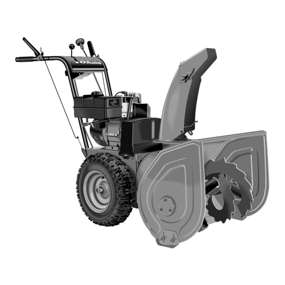
- Page 3 OPERATOR’S MANUAL Large Frame Snowthrower 860 Series Large Frame Snowthrower Mfg. No. Description 1693984 860M, 8HP Snowthrower 1693985 860M, 8HP Snowthrower (Export) 1694242 860E, 8HP Snowthrower 960 Series Large Frame Snowthrower Mfg. No. Description 1694435 960M, 9HP Snowthrower (Export) 1694439...
- Page 4 M A N U F A C T U R I N G , I N C . 500 N Spring Street / PO Box 997 Port Washington, WI 53074-0997 www.simplicitymfg.com © Copyright 2003, Simplicity Manufacturing, Inc. All Rights Reserved. Printed in USA.
-
Page 5: Table Of Contents
Safety Rules & Information General Operation ...2 Slope Operation...2 Children ...3 Emissions ...3 Service & Maintenance ...3 ANSI B71.3-1995 Warnings ...4 Identification Tags...5 Decals...6 Safety Icons ...7 Features, Controls, & Operation Control Locations...8 Starting Controls...10 Ground Speed Controls...11 Auger Control ...11 Deflector Controls...11 Scraper Height...11 Traction Lock Control ...11... -
Page 6: Safety Rules & Information
Safety Rules & Information Read these safety rules and follow them closely. Failure to obey these rules could result in loss of control of unit, severe personal injury or death to you, or bystanders, or damage to property or equipment. The triangle in text signifies important cautions or warnings which must be followed. -
Page 7: Children
CHILDREN Tragic accidents can occur if the operator is not alert to the presence of children. Children are often attracted to the unit and the operating activity. Never assume that children will remain where you last saw them. • Keep children out of the area and under the watchful care of another responsible adult. -
Page 8: Ansi B71.3-1995 Warnings
Safety Rules ANSI B71.3-1995 WARNINGS Training 1. Read the operating and service instruction manual carefully. Be thoroughly familiar with the controls and the proper use of the equipment. Know how to stop the unit and disengage the controls quickly. 2. Never allow children to operate the equipment. Never allow adults to operate the equipment without proper instruction. -
Page 9: Identification Tags
Engine RPM XXXX LpA: XXX dB(A) Vibration: XXX m/s² Simplicity Mfg. Inc. Port Washington, WI USA 53074-0997 When contacting your authorized dealer for replace- ment parts, service, or information you MUST have these numbers. Record your model name/number, manufacturer’s identi- fication numbers, and engine serial numbers in the space provided for easy access. -
Page 10: Decals
Safety Decals GENERAL This unit has been designed and manufactured to pro- vide you with the safety and reliability you would expect from an industry leader in outdoor power equipment manufacturing. Reading this manual and safety instructions it contains will provide you with the necessary basic knowledge to operate this equipment safely and effectively. -
Page 11: Safety Icons
Warning: Read Operator’s Manual. Read and understand the Operator’s Manual before using this machine. Danger: Thrown Objects. This machine is capable of throwing objects and debris. Keep bystanders away. Warning: Remove Key Before Servicing. Remove the key, disconnect spark plug wire, and consult technical litera- ture before performing repairs or maintenance. -
Page 12: Features, Controls, & Operation
Features, Controls, & Operation Please take a moment ALL MODELS and familiarize yourself with the 1,2.. name, location, and function of these controls so that you will better understand the safety and operating instructions provided in this manual. TECUMSEH MODELS BRIGGS &... -
Page 13: Control Locations
CONTROL LOCATIONS The information below briefly describes the function of individual controls. Starting, stopping, and driving require the combined use of several controls applied in specific sequences. To learn what combination and sequence of controls to use for various tasks see the OPERATION section. Speed Selector 1,2.. -
Page 14: Starting Controls
Engine Controls STARTING CONTROLS See Figure 1 for the following instructions. Units with Optional Electric Start A. Electric Start Button - The Electric Start Button (A) activates an electric starter mounted to the engine, eliminating the need to pull the starter han- dle. -
Page 15: Ground Speed Controls
GROUND SPEED CONTROLS A. Speed Selector - This lever (A, Figures 2 & 3) is used to set the ground speed of the snowthrower. The snowthrower has five forward speeds, 1–5, and two reverse speeds, 1–2. No neutral position or gate is required, since the traction drive design automati- cally provides "neutral"... -
Page 16: General Operation
Operation GENERAL OPERATION CHECKS BEFORE EACH START-UP 1. Make sure all safety guards are in place and all nuts, bolts and clips are secure. 2. Check the engine oil level. See your engine Owner’s Manual for procedure and specifications. 3. Check to make sure spark plug wire is attached and spark plug is tightened securely. -
Page 17: Starting The Engine
STARTING THE ENGINE Refer to Figure 4. 1. Turn the fuel valve (B) to the ON position. 2. Insert the engine key (F) into the engine key slot. 3. Move the throttle lever (E) to the FAST position. 4. Fully close the choke (G) if engine is cold (a warm engine may not require choking). -
Page 18: Operating The Snowthrower
Operation OPERATING THE SNOWTHROWER 1. Rotate the discharge chute to the desired direction. 2. Set the speed selector to the desired forward speed. 3. Fully press and hold the auger control (C, Figure 5) on the right-hand grip to begin auger rotation. To dis- engage the auger, completely release the lever. -
Page 19: Deflector
DEFLECTOR The distance of the discharged snow is mainly controlled by the position of the deflector (Figure 7). (Engine speed also affects distance of discharge.) The more the deflector is tilted UP, the farther snow will be thrown. Loosen the deflector knob, tilt the deflector UP or DOWN, and then retighten the knob when the desired angle has been chosen. -
Page 20: Free Wheeling And Traction Drive Lock
Operation FREE-WHEELING AND TRACTION DRIVE LOCK For easy turning when pushing the snowthrower, you can disengage the traction drive at one or both wheels by using the Traction Lock Pins (See Figures 9 & 10). 1. Turn the unit off, remove the Engine Key, and discon- nect the spark plug wire. -
Page 21: Schedule
1. Place the snowthrower on a level surface. 2. Remove the fill plug (Figure 12). 3. Check the lubricant level. It should be level with the lower edge of the plug opening. If not, add Simplicity Winter Weight Worm Gear Oil (available from your dealer). -
Page 22: Lubrication
Maintenance LUBRICATION IMPORTANT NOTE It is very important that grease fittings on the auger shaft are lubricated regularly. If auger rusts to shaft, damage to worm gear may occur if shear pins do not break. To prevent wheels rusting to axles, it is also necessary to remove the wheels and grease the axles regularly. -
Page 23: Check / Lube Free-Hand Linkage
CHECK / LUBRICATE FREE-HAND LINKAGE Check the function of the Free-Hand controls: the con- trols should function as described in the CONTROLS section. It is critical for the safe operation of the unit that the controls disengage when released. If the controls do not function properly, lubricate them (Figure 15). -
Page 24: Troubleshooting
Troubleshooting, Adjustments, & Service TROUBLESHOOTING This section provides troubleshooting and service instructions. Locate the problem and check the possible cause/remedy in the order listed. Also, refer to the engine manufacturer’s Owner’s Manual for additional information. For problems not covered here, contact your local dealer. PROBLEM Engine fails to start. - Page 25 PROBLEM Auger rotates, but snow is not thrown far enough Scraper bar does not clean hard surface. Scraper bar picks up and throws stones on gravel drive. Poor traction Auger does not stop when auger lever is released Snowthrower does not stop when drive lever is released Snowthrower does not drive when drive lever is engaged.
-
Page 26: Speed Selector Pivot Adjustment
Adjustments TRACTION DRIVE SYSTEM ADJUSTMENT Speed Selector Pivot Adjustment The Speed Selector is factory set for optimal perfor- mance at each forward and reverse speed setting. However, if drive system components have been replaced, adjustment may be necessary. Adjust as follows: 1. -
Page 27: Auger Drive System Adjustment
AUGER DRIVE SYSTEM ADJUSTMENTS Auger Drive Clutch Rod Adjustment WARNING Do not over-tighten, as this may lift the idler rod lever and cause auger drive to be engaged without depressing the Auger Control. All auger drive adjustment is accomplished through the auger drive clutch rod. -
Page 28: Discharge Chute Pinion Adjustment
Adjustment DISCHARGE CHUTE PINION ADJUSTMENT If the discharge chute is difficult to operate, first lubricate the pinion gear (A, Figure 21) and ring gear (F). If it is still difficult to operate, adjust as follows: 1. Loosen the nut (G, Figure 21) which holds the pinion gear bracket in the slotted hole. -
Page 29: Belt Replacement
Belt Cover Figure 23. Belt Cover BELT REPLACEMENT 1. Rotate the spout full right. Loosen the two screws (Figure 23) securing the belt cover. 2. Tilt the cover forward and work it off the snowthrower. 3. Remove the belt guide (B, Figure 25) by removing the two capscrews (A), lockwashers and washers. -
Page 30: Shear Pin Replacement
Service 6. Reverse the procedure to install the belts. Be sure there are no twists and the belts are properly seated in the grooves. Adjust the belt stops so there is 1/8” (3mm) clearance between belt and stop. The pattern for both belts is shown in Figure 26. -
Page 31: Specifications
Specifications are correct at the time of printing and are subject to change without notice. ENGINE: 8 HP* Tecumseh Make Tecumseh Model Snow King Horsepower 8 @ 3600 rpm Displacement 19.43 Cu. in (318.3 cc) Oil Capacity See Engine Owner’s Manual 9 HP* Briggs &... -
Page 32: Replacement Parts & Maintenance Items
Replacement Parts & Accessories REPLACEMENT PARTS Replacement parts are available from your authorized dealer. Always use genuine Simplicity Service Parts. MAINTENANCE ITEMS Many convenient and helpful service and maintenance items are available from you authorized dealer. Some of these items include:...