Table of Contents
Advertisement
How to use this file...(Operators Manuals)
————————————————————————————————————————————–––
Instructions for
Print Vendors (Paper Manuals)
Paper Size:
* 11 x 17
* Body—50 lbs brilliant white offset or equivalent.
* Cover—on pre-printed two-tone "Swash" stock.
P r e s s :
* Body—1-color, 2-sided
* Cover imprint —1-color, 1-sided
Bindery:
* Saddle Stitch, Face Trim
* Face Trim
C O V E R S :
* This file contains several manuals, which differ only in their covers.
* Covers are all present at the beginning of this file.
* Back cover for a particular manual is the page IMMEDIATELY AFTER the front cover.
• Check the front cover for the individual part number (typically a 171xxxx number).
B O D Y :
• The body of the manual is identical, regardless of the cover used.
* REMEMBER: ODD number pages are ALWAYS right hand pages, and EVEN number are ALWAYS
left hand pages.
G e n e r a l :
* This instruction page is NOT part of the manual and must NOT be printed.
• Pages labeled with the text "THIS PAGE INTENTIONALLY BLANK" are placement pages ONLY,
and should NOT be printed.
————————————————————————————————————————————–––
If you have further questions on how to utilize this file, please contact
Simplicity Technical Publications Department at (262) 284-8647.
Advertisement
Table of Contents

Related Manuals for Simplicity 1693650 860M


Summary of Contents for Simplicity 1693650 860M
- Page 1 • Pages labeled with the text “THIS PAGE INTENTIONALLY BLANK” are placement pages ONLY, and should NOT be printed. ————————————————————————————————————————————––– If you have further questions on how to utilize this file, please contact Simplicity Technical Publications Department at (262) 284-8647.
- Page 2 THIS PAGE INTENTIONALLY BLANK...
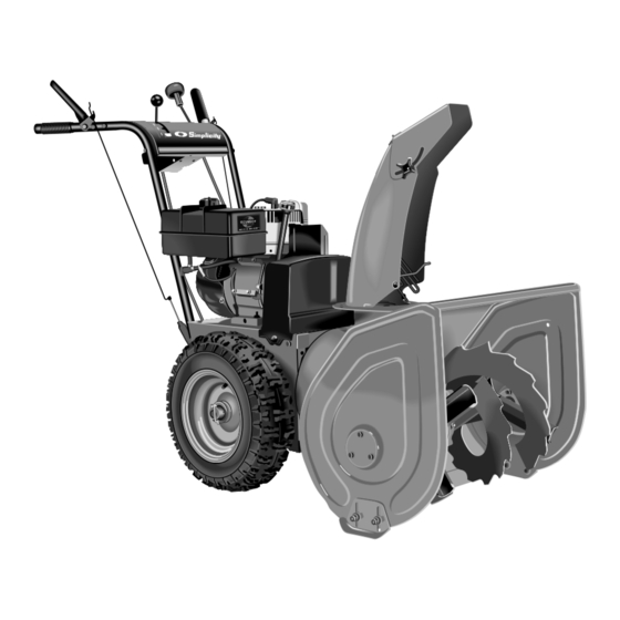
- Page 3 OPERATOR’S MANUAL Large Frame Snowthrower 860M LargeFrame Snowthrower Mfg. No. Description 1693650 860M, 8HP Snowthrower 1693651 860M, 8HP Snowthrower (Export) 1693763 860M, 8HP Snowthrower 1693775 860M, 8HP Snowthrower (Export) 1720535-01 Rev 4/2000 TP 100-2292-01-LW-S...
- Page 4 M A N U F A C T U R I N G , I N C . 500 N Spring Street / PO Box 997 Port Washington, WI 53074-0997 www.simplicitymfg.com © Copyright 2000, Simplicity Manufacturing, Inc. All Rights Reserved. Printed in USA.
-
Page 5: Table Of Contents
Engine exhaust from this product contains chemicals known, in certain quantities, to cause cancer, birth defects, or other reproductive harm. © Copyright 2000 Simplicity Manufacturing, Inc. All Rights Reserved. Printed In USA. TP 100-2292-01-LW-S REGULAR MAINTENANCE Normal Care Chart ...12 Off-Season Storage ...12... -
Page 6: Safety Rules
Safety Rules WARNING This unit is a “two-stage” snowthrower. The first stage is the auger, which feeds the snow back into the impeller housing. The second stage is the impeller, which throws the snow out the dis- charge chute. If bodily contact is made with the auger or impeller when they are rotating, severe personal injury will occur. -
Page 7: Operation
OPERATION • Keep hands and feet away from rotating parts. Keep clear of discharge opening at all times. • Always clear snow up and down the face of slopes, never across the face. Use extreme caution when changing direction on slopes. Do not attempt to clear slopes over 17.7% (10 •... -
Page 8: Safety Decals
Safety Decals SAFETY DECALS Safety warning decals are placed at strategic locations on the snowthrower as a constant reminder to the opera- tor of the most important safety precautions. All warning, caution and instructional messages on your snowthrow- er should be carefully read and obeyed. If any of these decals are lost or damaged, replace them at once. They can be purchased from your local dealer. -
Page 9: Snowthrower Controls
SNOWTHROWER CONTROLS Speed Selects Forward Speeds 1 - 5, Selector Reverse Speeds 1 - 2 Drive Control Engages drive to wheels as it is depressed; disengages when released. Auger Control Engages auger/impeller as it is depressed; disengages when released. Chute Direction Rotates discharge chute to Control desired direction... -
Page 10: Starting Controls
Controls STARTING CONTROLS Electric Start Units Only A. Electric Start Button - The Electric Start Button (A, Figure 3) activates an electric starter mounted to the engine, eliminating the need to pull the starter handle. The Electric Start Button operates on 120 Volts AC, which is provided by connection to the extension cord provided with units equipped with this feature. -
Page 11: Ground Speed Controls
GROUND SPEED CONTROLS A. Speed Selector - This lever (A, Figures 4 & 5) is used to set the ground speed of the snowthrower. The snowthrower has five forward speeds, 1–5, and two reverse speeds, 1–2. No neutral position or gate is required, since the traction drive design automati- cally provides "neutral"... -
Page 12: Operation
Operation GENERAL OPERATION CHECKS BEFORE EACH START-UP 1. Make sure all safety guards are in place and all nuts, bolts and clips are secure. 2. Check the engine oil level. See your engine Owner’s Manual for procedure and specifications. 3. Check to make sure spark plug wire is attached and spark plug is tightened securely. -
Page 13: Starting The Engine
STARTING THE ENGINE 1. Turn the fuel valve (B, Figure 6) to the ON position. 2. Insert the Engine Key (F) into the Engine Key slot and push fully in to the RUN position. 3. Move the Throttle Lever (E) fully up to the FAST posi- tion. -
Page 14: Ground Speed Selector
Operation GROUND SPEED SELECTOR Use the Speed Selector (A, Figure 8) to control the drive speed of the snowthrower. There are five forward speeds and two reverse speeds. Use the lower speeds to blow deep or wet snow. Use the higher speeds to blow light snow or to drive the snow- thrower without blowing snow. -
Page 15: Freewheeling/Traction Drive Lock
FREE-WHEELING AND TRACTION DRIVE LOCK For easy turning when pushing the snowthrower, you can disengage the traction drive at one or both wheels by using the Traction Lock Pins (See Figures 11 & 12.) 1. Turn the unit off, remove the Engine Key, and discon- nect the spark plug wire. -
Page 16: Regular Maintenance
To avoid this condition, add Simplicity Gasoline Stabilizer to the fuel tank, or drain all fuel from the system before placing unit in storage. 1. Prepare your snowthrower engine for storage as instructed in the Engine Owner’s Manual. -
Page 17: Checking Tire Pressure
Figure 14. Checking Tire Pressure CHECKING TIRE PRESSURE The air pressure in each tire should be 20 psi (136 kPa) and should be equal for both tires for best performance. Be sure to keep caps on valves to prevent entry of debris into the valve stem when tires are filled. -
Page 18: Troubleshooting, Adjustment, & Service Troubleshooting Chart
Troubleshooting, Adjustments, & Service TROUBLESHOOTING This section provides troubleshooting and service instructions. Locate the problem and check the possible cause/remedy in the order listed. Also, refer to the engine manufacturer’s Owner’s Manual for additional information. For problems not covered here, contact your local dealer. PROBLEM Engine fails to start. - Page 19 PROBLEM Auger rotates, but snow is not thrown far enough Scraper bar does not clean hard surface. Scraper bar picks up and throws stones on gravel drive. Poor traction Auger does not stop when auger lever is released Snowthrower does not stop when drive lever is released Snowthrower does not drive when drive lever is engaged.
-
Page 20: Traction Drive System Adjustment
Troubleshooting, Adjustments, & Service TRACTION DRIVE SYSTEM ADJUSTMENT Speed Selector Pivot Adjustment The Speed Selector is factory set for optimal perfor- mance at each forward and reverse speed setting. However, if drive system components have been replaced, adjustment may be necessary. Adjust as follows: 1. -
Page 21: Auger Drive System Adjustment
AUGER DRIVE SYSTEM ADJUSTMENTS Auger Drive Clutch Rod Adjustment WARNING Do not over-tighten, as this may lift the idler rod lever and cause auger drive to be engaged without depressing the Auger Control. All auger drive adjustment is accomplished through the auger drive clutch rod. -
Page 22: Belt Replacement
Troubleshooting, Adjustments, & Service Belt Cover Figure 22. Belt Cover BELT REPLACEMENT 1. Rotate the spout full right. Loosen the two screws (Figure 22) securing the belt cover. 2. Tilt the cover forward and work it off the snowthrower. 3. Remove the belt guide (B, Figure 24) by removing the two capscrews (A), lockwashers and washers. -
Page 23: Shear Pin Replacement
6. Reverse the procedure to install the belts. Be sure there are no twists and the belts are properly seated in the grooves. Adjust the belt stops so there is 1/8” (3mm) clearance between belt and stop. The pattern for both belts is shown in Figure 25. 7. -
Page 24: Discharge Control Adjustment
Troubleshooting, Adjustments, & Service DISCHARGE CONTROL ADJUSTMENT If the discharge chute is difficult to operate, first lubricate the pinion gear (A, Figure 27) and ring gear (F). If it is still difficult to operate, adjust as follows: 1. Loosen the nut (G, Figure 27) which holds the pinion gear bracket in the slotted hole. -
Page 25: Specifications
ENGINE Make ...Tecumseh Cylinders...1 Cycles...4 Crankshaft ...Horizontal 8 HP - Model No..See engine I.D. plate - Bore & Stroke ...3-1/8 in. x 2-17/32 in. - Displacement ...19.43 cu. in. Ignition ...Magneto Governor...Mechanical Choke ...Manual Lubrication ...Splash system Oil Capacity ...See engine manual Fuel Capacity...See engine manual TRACTION DRIVE Type...Friction drive transmission w/chain... -
Page 26: Replacement Parts & Accessories
Specifications COMMON REPLACEMENT PARTS Listed below are part numbers for the more common replacement parts. Use only genuine Simplicity replace- ment parts to assure optimum performance and safety. Simplicity Gas Stabilizer - 8 oz. Bottle...1685748 - Case of 12 Bottles (8 oz. ea.) ...1685747 Special Worm Gear Oil for Auger Gear Case - 8 oz.