Table of Contents
Advertisement
How to use this file...(Operators Manuals)
————————————————————————————————————————————–––
Instructions for
Print Vendors (Paper Manuals)
Paper Size:
* 11 x 17
* Body—50 lbs brilliant white offset or equivalent.
* Cover—on pre-printed two-tone "Swash" stock.
P r e s s :
* Body—1-color, 2-sided
* Cover imprint —1-color, 1-sided
Bindery:
* Saddle Stitch, Face Trim
* Face Trim
C O V E R S :
* This file contains several manuals, which differ only in their covers.
* Covers are all present at the beginning of this file.
* Back cover for a particular manual is the page IMMEDIATELY AFTER the front cover.
• Check the front cover for the individual part number (typically a 171xxxx number).
B O D Y :
• The body of the manual is identical, regardless of the cover used.
* REMEMBER: ODD number pages are ALWAYS right hand pages, and EVEN number are ALWAYS
left hand pages.
G e n e r a l :
* This instruction page is NOT part of the manual and must NOT be printed.
• Pages labeled with the text "THIS PAGE INTENTIONALLY BLANK" are placement pages ONLY,
and should NOT be printed.
————————————————————————————————————————————–––
If you have further questions on how to utilize this file, please contact
Simplicity Technical Publications Department at (414) 284-8650.
Advertisement
Table of Contents

Related Manuals for Simplicity 1693646 555M


Summary of Contents for Simplicity 1693646 555M
- Page 1 • Pages labeled with the text “THIS PAGE INTENTIONALLY BLANK” are placement pages ONLY, and should NOT be printed. ————————————————————————————————————————————––– If you have further questions on how to utilize this file, please contact Simplicity Technical Publications Department at (414) 284-8650.
- Page 2 THIS PAGE INTENTIONALLY BLANK...
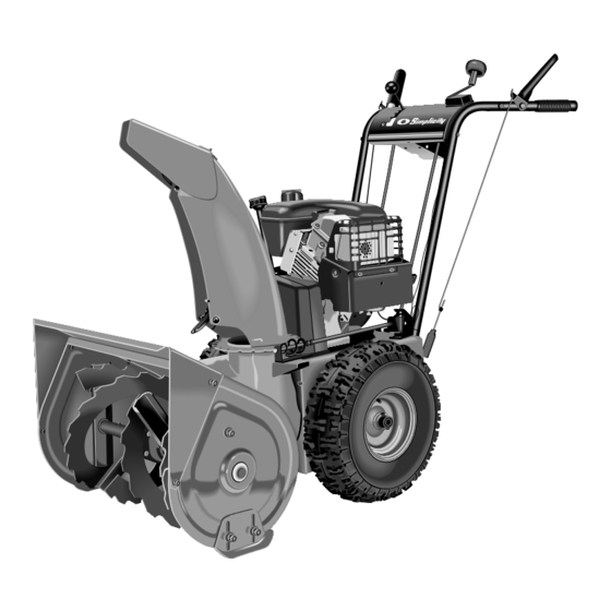
- Page 3 OPERATOR’S MANUAL Intermediate Snowthrower Models 555 Models Mfg. No. Description 1693646 555M, 5HP Snowthrower, Manual Start 1693647 555M, 5HP Snowthrower, Manual Start (Export) 755 Models Mfg. No. Description 1693648 755M, 7HP OHV Snowthrower, Manual Start 1693649 755M, 7HP OHV Snowthrower, Manual Start (Export) 1720407-00 Rev 6/1999 TP 100-2253-00-IW-S...
- Page 4 M A N U F A C T U R I N G , I N C . 500 N Spring Street / PO Box 997 Port Washington, WI 53074-0997 www.simplicitymfg.com © Copyright 1999, Simplicity Manufacturing, Inc. All Rights Reserved. Printed in USA.
-
Page 5: Table Of Contents
WARNING Engine exhaust from this product contains chemicals known, in certain quantities, to cause cancer, birth defects, or other reproductive harm. © Copyright 1999 Simplicity Manufacturing, Inc. All Rights Reserved. Printed In USA. TP 100-2253-00-IW-S 2062-03 REGULAR MAINTENANCE Normal Care Chart ...13 Off-Season Storage ...13... -
Page 6: Safety Rules
Safety Rules WARNING This unit is a “two-stage” snowthrower. The first stage is the auger, which feeds the snow back into the impeller housing. The second stage is the impeller, which throws the snow out the discharge chute. If bodily contact is made with the auger or impeller when they are rotating, severe personal injury will occur. -
Page 7: Operation
OPERATION • Keep hands and feet away from rotating parts. Keep clear of discharge opening at all times. • Always clear snow up and down the face of slopes, never across the face. Use extreme caution when changing direction on slopes. Do not attempt to clear slopes over 17.7% (10 •... -
Page 8: Safety Decals
Part No. 1715558 Simplicity Logo Decal SNO-AWAY 55cm Part No. 1714107 (755) Or Part No. 1714108 (555) Simplicity Logo Auger Decal WARNING TO AVOID SERIOUS INJURY • Read Owner’s Manual before operating unit. • Never allow children to operate snowthrower. -
Page 9: Control Reference Chart
SNOWTHROWER CONTROLS Speed Selects Forward Speeds 1 - 5, Selector Reverse Speeds 1 - 2 Drive Control Engages drive to wheels as it is depressed; disengages when released. Auger Control Engages auger/impeller as it is depressed; disengages when released. Chute Direction Rotates discharge chute to Control desired direction... -
Page 10: Controls Starting Controls
Controls STARTING CONTROLS Units with Optional Electric Start A. Electric Start Button - The Electric Start Button (A, Figures 4 & 5) activates an electric starter mount- ed to the engine, eliminating the need to pull the starter handle. The Electric Start Button operates on 120 Volts AC, which is provided by connection to the extension cord provided with units equipped with this feature. -
Page 11: Ground Speed Controls
GROUND SPEED CONTROLS A. Speed Selector - This lever (A, Figures 6 & 7) is used to set the ground speed of the snowthrower. The snowthrower has five forward speeds, 1–5, and two reverse speeds, 1–2. No neutral position or gate is required, since the traction drive design automati- cally provides "neutral"... -
Page 12: General Operation
Operation GENERAL OPERATION CHECKS BEFORE EACH START-UP 1. Make sure all safety guards are in place and all nuts, bolts and clips are secure. 2. Check the engine oil level. See your engine Owner’s Manual for procedure and specifications. 3. Check to make sure spark plug wire is attached and spark plug is tightened securely. -
Page 13: Starting The Engine
STARTING THE ENGINE 1. Turn the fuel valve (B, Figures 8 & 9) to the ON posi- tion. 2. Insert the Engine Key (F, Figures 8 & 9) into the Engine Key slot and push fully in to the RUN position. 3. -
Page 14: Operating The Snowthrower
Operation OPERATING THE SNOWTHROWER 1. Rotate the discharge chute to the desired direction. 2. Set the Speed Selector to the desired forward speed. 3. Fully press and hold the Auger Control (C, Figure 10) on the right-hand grip to begin auger rotation. To dis- engage the auger, completely release the lever. -
Page 15: Deflector
DEFLECTOR The distance of the discharged snow is mainly controlled by the position of the deflector (Figure 12). (Engine speed also affects distance of discharge.) The more the deflector is tilted UP, the farther snow will be thrown. Loosen the deflector knob, tilt the deflector UP or DOWN, and then retighten the knob when the desired angle has been chosen. -
Page 16: Free Wheeling And Traction Drive Lock
Operation FREE-WHEELING AND TRACTION DRIVE LOCK For easy turning when pushing the snowthrower, you can disengage the traction drive at one or both wheels by using the Traction Lock Pins (See Figures 14 & 15.) 1. Turn the unit off, remove the Engine Key, and discon- nect the spark plug wire. -
Page 17: Regular Maintenance
(30 days or longer), may develop gummy deposits which can adversely affect the engine carbure- tor and cause engine malfunction. To avoid this condi- tion, add Simplicity Gasoline Stabilizer to the fuel tank, or drain all fuel from the system before placing unit in stor- age. -
Page 18: Lubrication
Regular Maintenance LUBRICATION IMPORTANT NOTE It is very important that grease fittings on the auger shaft are lubricated regularly. If auger rusts to shaft, damage to worm gear may occur if shear pins do not break. To prevent wheels rusting to axles, it is also necessary to remove the wheels and grease the axles regularly. -
Page 19: Maintenance Records
Regular Maintenance MAINTENANCE RECORDS:... -
Page 20: Service
Service TROUBLESHOOTING This section provides troubleshooting and service instructions. Locate the problem and check the possible cause/remedy in the order listed. Also, refer to the engine manufacturer’s Owner’s Manual for additional information. For problems not covered here, contact your local deal- PROBLEM Engine fails to start. - Page 21 PROBLEM Auger rotates, but snow is not thrown far enough Scraper bar does not clean hard surface. Scraper bar picks up and throws stones on gravel drive. Poor traction Auger does not stop when auger lever is released Snowthrower does not stop when drive lever is released Snowthrower does not drive when drive lever is engaged.
-
Page 22: Speed Selector Pivot Adjustment
Service SPEED SELECTOR PIVOT ADJUST- MENT The Speed Selector is factory set for optimal perfor- mance at each forward and reverse speed setting. However, if drive system components have been replaced, adjustment may be necessary. Adjust as follows: 1. Move the ground speed control (A, Figure 20) fully forward. -
Page 23: Auger Drive Clutch Rod Adjustment
AUGER DRIVE CLUTCH ROD ADJUSTMENT The auger drive clutch rod should be adjusted so that there is no slack in the rod when moved slightly from side to side. To adjust tension on the rod: 1. Loosen adjustment hex nuts (Figure 22). 2. -
Page 24: Adjusting Auger Drive Belt
Service DRIVE BELT ADJUSTMENT If the auger drive slips (auger slows or doesn't rotate nor- mally while blowing snow), or stays engaged when the control is disengaged — and the auger clutch rod has been properly adjusted — the auger drive belt may be out of adjustment. -
Page 25: Adjusting Auger Belt Guide
DRIVE BELT ADJUSTMENT Adjusting Auger Belt Guide 1. With the Auger Control still fully depressed, adjust the Auger Belt Guide so that there is a 1/64” gap (1/32” Maximum) between the end of the guide and the belt (Figure 27), making certain the guide is NOT putting pressure on the belt. -
Page 26: Auger Drive Belt Replacement
Service DRIVE BELT REPLACEMENT Auger Drive Belt Replacement 1. Remove gas from fuel tank and run engine until it stops running from lack of fuel. 2. Disconnect spark plug wire and fasten it away from the spark plug. 3. Remove belt cover (See Figure 27). 4. -
Page 27: Roller Chain Replacement
ROLLER CHAIN REPLACEMENT NOTE: This procedure does not apply to models that use an “endless” chain. 1. Remove gas from fuel tank and run engine until it stops running from lack of fuel. 2. Disconnect spark plug wire and fasten it away from the spark plug. -
Page 28: Discharge Chute Worm Assy. Adjustment
Service DISCHARGE CHUTE WORM ASSEMBLY ADJUSTMENT If the Discharge Chute becomes difficult to rotate or begins to operate erratically, the Worm Assembly may require adjustment: 1. Loosen the adjustment screw under the Worm Assembly mounting area (Figure 33). 2. Slide the Worm Assembly in or out to provide smooth engagement between the worm wire and the slots in the base of the Discharge Chute. -
Page 29: Specifications
ENGINE Make ...Tecumseh Cylinders...1 Cycles...4 Crankshaft ...Horizontal 5 HP (555M) - Model No..See engine I.D. plate - Bore & Stroke...2.795 in. x 1.937 in. (70.99 mm x 49.20 mm) - Displacement ...11.88 cu. in. 7 HP (755E) - Model No..See engine I.D. plate - Bore &... -
Page 30: Replacement Parts & Accessories
Replacement Parts & Accessories COMMON REPLACEMENT PARTS Listed below are part numbers for the more common replacement parts. Use only genuine Simplicity replace- ment parts to assure optimum performance and safety. Simplicity Gas Stabilizer - 8 oz. Bottle ...1685748 - Case of 12 Bottles (8 oz. ea.) ...1685747 Special Worm Gear Oil for Auger Gear Case - 8 oz.