Table of Contents
Advertisement
Advertisement
Table of Contents

Related Manuals for Briggs & Stratton 030430


Summary of Contents for Briggs & Stratton 030430
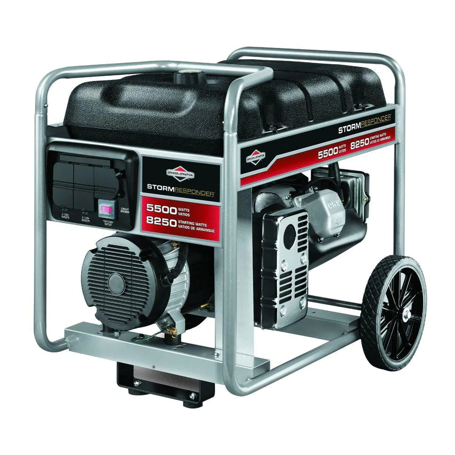
- Page 1 Service and Repair Manual 5500 Watt Portable Generator — Model 030430 This generator is rated in accordance with CSA (Canadian Standards Association) standard C22.2 No. 100-04 (motors and generators). BRIGGS & STRATTON POWER PRODUCTS GROUP, LLC Manual No. 279787GS Revision A...
- Page 2 Briggs & Stratton Power Products Group, LLC P.O. Box 702 Milwaukee, WI 53201-0702 Copyright © 2010. All rights reserved. No part of this material may be reproduced or transmitted in any form without the express written permission of Briggs & Stratton Power Products Group, LLC. BRIGGSandSTRATTON.COM...
-
Page 3: Table Of Contents
Table of Contents Important Safety Instructions ......4 Generator Components ......7 Alternator Components . -
Page 4: Important Safety Instructions
Save These Instructions Equipment Description Important Safety Instructions Read this manual carefully and become familiar The manufacturer cannot possibly anticipate every possible with your generator. Know its applications, its circumstance that might involve a hazard. The warnings in limitations and any hazards involved. this manual, and the tags and decals affixed to the unit are, therefore, not all-inclusive. - Page 5 WARNING Starter cord kickback (rapid retraction) will pull hand and arm toward engine faster than you can let go, which could cause broken bones, fractures, bruises, or sprains resulting in serious injury. • When starting engine, pull cord slowly until resistance is felt and then pull rapidly to avoid kickback.
- Page 6 WARNING Generator voltage could cause electrical WARNING Starter and other rotating parts could shock or burn resulting in death or serious injury. entangle hands, hair, clothing, or accessories resulting in serious injury. • NEVER operate generator without protective housing or •...
-
Page 7: Generator Components
Generator Components A - Fuel Tank — Capacity of seven (7) U.S. gallons (26.5 L) K - Identification Label — Provides model, revision, and serial number of generator. Please have this readily B - Fuel Valve — Used to turn fuel supply on and off to available when calling for assistance. -
Page 8: Alternator Components
Alternator Components A - Alternator Adapter B - Rotor Assembly C - Slip Rings D - Stator E - Roll Pin F - Rear Bearing Carrier G - Taptite H - Brush Holder / Bridge Rectifier Assembly J - Hex-Head Cap Screw BRIGGSandSTRATTON.COM... - Page 9 Brush Holder / Bridge Rectifier Assembly How it Works Figure 3 is an operating diagram of a revolving field This generator is equipped with a bridge rectifier (A, Figure 1) alternator with a bridge rectifier. attached to the brush holder assembly (B). Figure 1 The brush holder is mounted to the rear bearing carrier.
-
Page 10: Generator Troubleshooting
Generator Troubleshooting Refer to Figure 4 for wire identification and locations when performing the troubleshooting procedures. LEGEND WIRE NUMBER WIRE COLOR Green Blue Blue Black Gray Figure 4 BRIGGSandSTRATTON.COM... - Page 11 Figure 5 is a troubleshooting flowchart for “Direct Excited” (Brush Type) generators. Test 1: Check AC output voltage and frequency Low voltage Low voltage less than 1 and frequency volt or zero ? Check and Adjust Test 2: Engine Governor Flash the Field Output Output...
- Page 12 TEST 1 - Check Voltage and Frequency Output In normal generator operation, upon startup there is some “residual” magnetism in the rotor to get the generating 1. Disconnect any electrical loads. process started. Residual magnetism is what is left in the 2.
- Page 13 TEST 3 - Isolate Control Panel A “No Output” condition may or may not be related to the alternator windings. To help isolate where the issue is, follow these steps: 1. With the engine OFF, disconnect the power lead harness from the back of the control panel. 2.
- Page 14 Measure Winding Resistance Test Stator AC Power Winding Resistance 1. Set meter to measure Ohms. 2. Connect the test leads to stator wires #11 and #22 located in the harness going to the control panel connector (Figure 8). Figure 9 5.
- Page 15 Test Stator Excitation Winding Resistance 5. Connect one test lead to an excitation wire. Connect the other test lead to a proper metal ground. The excitation wires may be colored (red and blue) or • A reading of infinity should be measured. numbered (#2 and #6).
-
Page 16: Alternator Disassembly
Alternator Disassembly Refer to Figure 12 for part identification and to aid in the diasassembly of the alternator. Figure 12 G - Steel Laminations A - Plastic End Cover H - Alternator Adapter B - Rotor Through Bolt J - Engine Adapter C - Mounting Screws (2) for Brush Holder K - Mounting Screws (4) for Adapters D - Rear Bearing Carrier... - Page 17 Remove the Stator Assemble the Alternator Ensure the engine/alternator assembly is set on a sturdy 1. Install the rotor and torque to values listed in work surface. Do not set the engine/alternator assembly on Specifications. the plastic end cover. 2. With stator harness and lead wires facing away from 1.
- Page 18 4. Pull wires up through rear bearing carrier (A, Figure 6. Insert stator bolts into each hole around the rear 15). Set rear bearing carrier on rotor bearing and bearing carrier. Tighten bolts in a criss-cross pattern stator. Verify second roll pin slot (B) in stator lines up until snug, then torque to values listed in Generator with roll pin (C) in rear bearing carrier.
-
Page 19: Generator Specifications
7 U.S. gallons (26.5 L) Oil Capacity 28 Ounces (0.83 Liters) Resistance Values Winding Resistance 030430-2 Rotor (at the slip rings) 24.3 - 29.1 Ohm Power (wires 11-22 & 33-44) 0.19 - 0.24 / 0.19 - 0.24 Ohm Excitation (wires 2-6) 1.26 - 1.50 Ohm... -
Page 20: Generator Wiring Diagram
Generator Wiring Diagram BRIGGSandSTRATTON.COM... -
Page 21: Generator Schematic
Generator Schematic... - Page 22 Notes BRIGGSandSTRATTON.COM...
-
Page 23: Engine Maintenance
Engine Maintenance Fuel and Oil Recommendations Maintenance Chart Fuel must meet these requirements: First 5 Hours • Clean, fresh, unleaded gasoline. • Change oil • A minimum of 87 octane / 87 AKI (90 RON). Every 8 Hours or Daily •... - Page 24 Air Filter Maintenance Spark Plug Maintenance Spark plugs should be replaced every year. A correctly serviced air fi lter protects internal engine parts from airborne dirt and dust. Poor fi lter maintenance will allow NOTICE: Spark plugs have different thread “reach” and heat dirt and dust to be drawn into the engine, causing wear to ranges.
- Page 25 Cooling System Maintenance Inspect Exhaust System All exhaust system components must be inspected whenever the exhaust system is disassembled. Check muffl er mounting Dirt or debris can restrict air fl ow and cause the engine to bracket and/or muffl er adapters for cracked welds or break- overheat, resulting in poor performance and reduced engine age.
- Page 26 Oil and Oil Filter Maintenance Change oil after the fi rst 5 hours of operation. After that, change oil after every 50 hours of operation. Change oil more often if engine is operated in dirty or dusty conditions, under heavy loads, or in high ambient temperatures. 1.
-
Page 27: Engine Adjustments
Engine Adjustments Governor Adjustments Idle and Top No Load Adjustment A complete governor system adjustment includes a static 1. Start engine and run until it reaches operating adjustment, engine warm-up, idle and/or governed idle temperature. adjustment, and top no-load adjustment. Be sure to complete all steps. - Page 28 Adjust Valve Clearance NOTE: Check valve clearance while the engine is cold. 1. Turn crankshaft counterclockwise until piston is at top dead center on the compression stroke. This prevents the compression release from holding the valves open. 2. Insert a narrow screwdriver or rod into the spark plug hole as a gauge, then slowly turn crankshaft counterclockwise until the piston has moved down the bore by 1/4”...
-
Page 29: Fuel System And Carburetion
Fuel Systems and Carburetion Fuel Tanks and Shut-off Valves WARNING Fuel and its vapors are extremely flammable and explosive which could cause Removal burns, fire or explosion resulting in death, serious injury and/or property damage. 1. Close shut-off valve, if equipped. WHEN ADDING OR DRAINING FUEL 2. - Page 30 Inspection Carburetor Service 1. Clean gummy or dirty fuel tanks with Briggs & Stratton Carburetor Cleaner #100041 or #100042, or equivalent. LMT Carburetor 2. Inspect fuel tank for: • Corrosion Two versions of this carburetor have been used (Figures 25 and 26).
- Page 31 Remove Carburetor 3. Remove float hinge pin, float, and inlet needle. Discard the hinge pin and inlet needle. 1. Remove air cleaner assembly. Discard the gasket. 4. Screw a 1/4-20 tap into fuel inlet seat 3-4 turns and 2. Move clamp and disconnect hose from carburetor. remove.
- Page 32 - OR - Assemble Carburetor Consult the Illustrated Parts List to obtain the appropriate If carburetor is equipped with a metal choke shaft, rotate carburetor overhaul kit before reassembling the carburetor. choke shaft to closed position. Remove two choke valve 1.
- Page 33 - OR - 5. Install idle speed screw and spring, then install idle 3. If carburetor is equipped with a plastic choke shaft, mixture screw with spring and turn until head of screw touches spring. • Install new foam seal and return spring on choke shaft (C, Figure 33) with straight end of spring against choke 6.
- Page 34 Install Carburetor NOTE: Always replace air cleaner gaskets and carburetor mounting gaskets any time the carburetor has been removed for service. 1. Position new gasket on studs with long edge of gasket opposite fuel inlet of carburetor. 2. Hook governor spring (B, Figure 37) in throttle lever hole without grommet.
-
Page 35: Governor System
Governor Systems Linkage and Spring Orientation Governor Service NOTE: Be sure to note hole position of linkage before removing. The mechanical governor is part of the crankcase cover. The governor gear (A, Figure 40) is driven by the crankshaft timing gear (B) through an idler gear (C). The governor crank (D) is mounted in the cylinder assembly. - Page 36 Inspect Governor Assemble 1. Check governor gear assembly for worn weight pins, 1. Install governor crank from inside cylinder. Slide worn or damaged governor cup, and chipped or washer (when used) on crank and install new push nut. damaged teeth. 2.
-
Page 37: Cylinder Head And Valves
Cylinder Head and Valves Before the cylinder head can be removed, other external parts must be removed, such as the air cleaner, fuel tank, oil fi ll tube, blower housing, muffl er, carburetor, control bracket assembly, and intake manifold. Remove Cylinder Head 1. - Page 38 3. If guides are replaced, or the original guides still meet 4. Oil inside diameter of new stem seal/washer and install specifications, use Finish Reamer #19066 and Reamer on intake valve stem. Slide seal down against head Guide #19191 to ensure proper sizing and to clean out plate or cylinder head.
- Page 39 NOTE: Do not torque each screw in one step as it may result in a warped cylinder head. Step-torque all screws to approxi- mately 1/3 of fi nal torque value, then to 2/3 fi nal torque value, then fi nish at fi nal torque values. 3.
-
Page 40: Starters
Starters 5. Carefully drill through all rivet heads and remove On some engines, the rewind starters are attached to the rewind starter. Do not allow drill bit to cut into the blower housing with screws and can be quickly removed. holes in the starter housing. - Page 41 Inspect Rewind Starter Parts 8. Carefully release the clamp on the starter and allow the pulley to SLOWLY unwind until the rope is retracted. NOTE: Do not remove the spring from the pulley. Both parts Smoothly pull the rope handle several times to ensure are serviced only as an assembly.
-
Page 42: Lubrication Systems
Lubrication Systems Extended Oil Fill and Dipstick Check Breather 1. Gently blow air into the breather tube. There should be no air flow out the valve. These models use a plastic extended oil fi ll tube and a quarter-turn dipstick. The oil fi ll tube screws into the crank- 2. -
Page 43: Cylinders, Covers, And Sumps
Cylinders, Covers and Sumps Inspect Cylinder Compare measurements to the standard cylinder bore sizes provided in Engine Specifi cations. If the cylinder bore is more than 0.003 in. (0.08 mm) 1. Visually check cylinder for cracks, stripped threads, and oversize, or 0.0015 in. (0.04 mm) out of round, it must be bore damage. - Page 44 Cleaning Cylinder Covers and Sumps 1. Wash the cylinder thoroughly in a solvent such as Installation kerosene or other commercial solvent. 1. Place seal protector on oil seal. 2. Wash cylinder again using a stiff brush with soap and 2. Make sure mechanical governor fear and oil pump hot water.
-
Page 45: Crankshafts And Camshafts
Crankshafts and Camshafts Remove Crankshaft and Camshaft Check Crankshaft 1. Inspect crankshaft for scoring on mag journal (A, Figure 1. Drain oil from engine and all fuel from fuel tank. 63), crankpin journal (B), and PTO journal (C). Replace 2. Remove blower housing/rewind assembly and flywheel/ crankshaft if scoring is found or if crankshaft is bent. - Page 46 Install Crankcase Cover or Sump 1. Using a new gasket, install crankcase cover or sump using seal protectors. Do not force cover or sump on cylinder. NOTE: It may be necessary to rotate idler gear to mesh with timing gear when installing cover. 2.
-
Page 47: Piston, Rings, And Connecting Rod
Pistons, Rings, and Connecting Rods Remove Piston and Connecting Rod 4. Using Piston Ring Expander #19340 (Figure 71), 1. Carefully remove any carbon or ridge at top of cylinder remove rings one at a time. Not the order and bore to prevent ring breakage. orientation of the rings before removal. - Page 48 Check Connecting Rod If the crankpin bearing (A, Figure 74) or the piston pin bearing (B) is scored, the rod must be replaced. 1. Reinstall rod cap and bolts on rod. 2. Using a dial caliper or plug gauge, measure the two bearing diameters.
- Page 49 3. Install a pin retainer into groove on open side of piston 4. Fit connecting rod bearing on crankpin journal, then pin bore. Ensure retainers are firmly seated in grooves. install rod cap with match marks aligned. 4. Using Piston Ring Expander #19340, install oil ring and 5.
-
Page 50: Engine Specifications
Engine Specifications Engine Specifications - Model 200000 Horizontal Series ENGINE SPECIFICATIONS Armature Air Gap 0.010 - 0.014 in. (0.25 - 0.36 mm) Crankshaft End Play 0.002 - 0.028 in. (0.05 - 0.71 mm) Spark Plug Gap 0.030 in. (0.76 mm) Valve Clearance - Intake 0.004 - 0.006 in. - Page 51 REJECT DIMENSIONS STANDARD SIZE REJECT SIZE CYLINDER Main Bearing 0.876 in. (22.25 mm) 0.878 in. (22.30 mm) Camshaft Bearing 0.5011 in. (15.88 mm) 0.504 in. (12.80 mm) Bore Diameter 2.688 in. (65.10 mm) 2.691 in. (68.33 mm) Bore Out-of-Round 0.0015 in. (0.04 mm) CYLINDER HEAD Valve Guide 0.249 in.
- Page 52 Engine Specifications - Model 210000 Horizontal Series ENGINE SPECIFICATIONS Armature Air Gap 0.010 - 0.014 in. (0.25 - 0.36 mm) Crankshaft End Play 0.002 - 0.028 in. (0.05 - 0.71 mm) Spark Plug Gap 0.030 in. (0.76 mm) Valve Clearance - Intake 0.004 - 0.006 in.
- Page 53 REJECT DIMENSIONS STANDARD SIZE REJECT SIZE CYLINDER Main Bearing 1.1825 in. (30.03 mm) 1.184 in. (30.07 mm) Camshaft Bearing 0.5011 in. (15.88 mm) 0.504 in. (12.80 mm) Bore Diameter 3.300 in. (83.82 mm) 3.304 in. (83.92 mm) Bore Out-of-Round 0.0015 in. (0.04 mm) CYLINDER HEAD Valve Guide 0.236 in.
- Page 54 Engine Specifications - Model 210000 Vertical Series ENGINE SPECIFICATIONS Armature Air Gap 0.010 - 0.014 in. (0.25 - 0.36 mm) Crankshaft End Play 0.002 - 0.034 in. (0.05 - 0.86 mm) Spark Plug Gap 0.030 in. (0.76 mm) Valve Clearance - Intake 0.004 - 0.006 in.
- Page 55 REJECT DIMENSIONS STANDARD SIZE REJECT SIZE CYLINDER Main Bearing 1.3795 in. (35.04 mm) 1.383 in. (35.13 mm) Camshaft Bearing 0.5011 in. (15.88 mm) 0.504 in. (12.80 mm) Bore Diameter 3.437 in. (87.30 mm) 3.441 in. (87.40 mm) Bore Out-of-Round 0.0015 in. (0.04 mm) CYLINDER HEAD Valve Guide 0.237 in.
-
Page 56: Generator Illustrated Parts List
Generator Illustrated Parts List ALTERNATOR IDENTIFICATION: The identification label/data tag provides model, revision, and serial number of generator. It is necessary to know the model number as well as the revision number when determining the type of alternator used on your generator. Identification Label / Data Tag Generator Model Number Generator Revision Number... - Page 57 Alternator NOTICE: Alternator Identification. Use this exploded view on Model 030430 Generators that have a Revision Number of 02. See data tag for revision number. Item Part # Description 186059GS ADAPTER, Mounting, Alternator 204105GS ASSY., Rotor (Includes Item 8) 208368GS...
- Page 58 Main Unit BRIGGSandSTRATTON.COM...
- Page 59 Main Unit Parts List - Main Unit Item Part # Description Item Part # Description 209877BUGS CRADLE (Includes Items 20 & 31) 32 200658GS DECAL 209287BUGS HANDLE 34 195422GS COVER-REAR BEARING 67989GS 35 791745 HOSE-FUEL (cut to fit) 190220GS ADAPTER-ENGINE 36 192376GS SCREW ALTERNATOR...
-
Page 60: Control Panel
Control Panel Item Part # Description 201571GS PANEL-CONTROL 197472GS COVER-OUTLET 201572GS BOX-CONTROL PANEL 197731GS OUTLET-120V 20A 189164GS PALNUT-3/16 202951GS LAMP-LED SCREW-3 x 6, TAPPING 209676GS BREAKER-CIRCUIT 23A 191481GS BOOT (not shown) 43437GS OUTLET-120/240V TL30A 10 201678GS CONNECTOR-6 PIN 11 * PPPHS-M3-0.5 x 12 * - Items without part numbers are common fasteners and are available at local hardware stores. -
Page 61: Wheel Kit
Wheel Kit Item Part # Description 207175GS WHEEL WASHER-5/8 208101GS AXLE 191265GS E-RING HHCS-M8 1.25 x 20 67989GS 189522ZGS SUPPORT-LEG Parts Not Illustrated 196157GS KIT-HARDWARE * - Items without part numbers are common fasteners and are available at local hardware stores. -
Page 62: Engine Illustrated Parts List
Engine Illustrated Parts List ENGINE IDENTIFICATION: The engine model, type, trim, and date code are located on the valve cover. It is necessary to know the code as well as the model and type number when performing adjustments, repairs, or ordering replacement parts. - Page 63 Engine 216300 1058 OPERATOR’S MANUAL 1330 REPAIR MANUAL 1319 WARNING LABEL REQUIRED when replacing parts with warning labels affixed. 306A 307A 1194 718A...
- Page 64 Engine 216300 1171 1023 1022 1022 1029 1100 883A 1026 358 ENGINE GASKET SET 1095 VALVE GASKET SET 883A 1022 1022 BRIGGSandSTRATTON.COM...
- Page 65 Engine 216300 633B 109D 109E 108A 633B 633B 633B 130A 127A 105A 105A 104A 133A 104A 133A 632A 975A 137A 1127A 1127A 141C 109D 109E 108A 108A 633B 633B 121A CARBURETOR OVERHAUL KIT 121 CARBURETOR OVERHAUL KIT 127A 127A 137A 104A 104A 105A...
- Page 66 Engine 216300 968A 425A 161B 836B 300E 832B 676C 883A 677A 613B 300C 836C 436C 832C 1177 863C 883C 740A NOTE: This muffler is intended for replacement purposes only and is not to be used for retrofitting to engines with different exhaust systems.
- Page 67 Engine 216300 1036 EMISSIONS LABEL 1298 1212 725A 727A 1005 1070 1210 1211...
- Page 68 Engine 216300 972A 957A 187A 1404 1230 1138 271A 222B 604A BRIGGSandSTRATTON.COM...
- Page 69 Engine 216300 493A 500A 892A 364A 990A 1052A 10--16 AMP 577A 474D 578A 627A NOTE: All stators use a No. 1119 mounting screw. 347B NOTE: The proper flywheel part number and/or the alternator magnet size will 1119 determine the alternator type or output. See repair instruction manual for additional information.
- Page 70 Engine 216300 DESCRIPTION DESCRIPTION DESCRIPTION 794850 Cylinder Assembly 24 222698S Key--Flywheel 690975 Lock--Piston Pin 698340 Kit--Bushing/Seal 793318 Piston Assembly 696581 Pin--Piston (Standard) 694691 Rod--Connecting (Magneto Side) (Used After Code Date 694692 Dipper--Connecting 3 391086S Seal--Oil 08032300). (Magneto Side) - - - - - - - - - - - - - - Note - - - - - - - - - - 690976 Screw 794870 Head--Cylinder 793794 Piston...
- Page 71 Engine 216300 DESCRIPTION DESCRIPTION DESCRIPTION 796334 Shaft--Throttle 796333 Jet--Main 121A 696146 Kit--Carburetor (Used After Code Date (High Altitude) Overhaul 08071700). (Used After Code Date (Used Before Code - - - - - - - - - - - - - - Note - - - - - - - - - - 08071700).
- Page 72 Engine 216300 DESCRIPTION DESCRIPTION DESCRIPTION 698781 Gasket--Float Bowl 794799 Bracket--Control 306A 697240 Shield--Cylinder (Used After Code Date Used on Type No(s). 307A 794822 Screw 08071700). 0036, 0112, 0113, (Cylinder Shield) - - - - - - - - - - - - - - Note - - - - - - - - - - 0116, 0118, 0541.
- Page 73 Engine 216300 DESCRIPTION DESCRIPTION DESCRIPTION 695422 Spring--Float Bowl 793515 Nut 794846 Screw (Used Before Code (Governor Control (Muffler) Date 08071800). Lever) 613B 794844 Screw - - - - - - - - - - - - - - Note - - - - - - - - - - (Muffler) (Used After Code Date 695422 Spring--Float...
- Page 74 Engine 216300 DESCRIPTION DESCRIPTION DESCRIPTION 691087 Nut 694482 Cap--Drive 698783 Bowl--Float (Key Switch) 691286 Cap--End (Used After Code Date Used on Type No(s). 690635 Clamp 08071700). 0116. 794832 Screw - - - - - - - - - - - - - - Note - - - - - - - - - - 694257 Spacer (Muffler Bracket) 698783 Bowl--Float...
- Page 75 Engine 216300 DESCRIPTION DESCRIPTION DESCRIPTION 1090 691293 Retainer--Brush 1177 710090 Nut 1212 794841 Stud 1095 695440 Gasket Set--Valve (Muffler) (Blower Housing) 1100 791959 Pivot--Rocker Arm 1194 691876 Seal--O Ring 1230 794840 Stud 1119 699772 Screw (Plug) (Control Bracket) (Alternator) 1210 498144 Pulley/Spring 1298 794838 Nut...