Lantronix PremierWave 2050 Integration Manual
802.11ac embedded wi-fi iot gateway
Hide thumbs
Also See for PremierWave 2050:
- Command reference manual (428 pages) ,
- User manual (73 pages) ,
- Integration manual (30 pages)
Table of Contents
Advertisement
Quick Links
Download this manual
See also:
User Manual
Advertisement
Table of Contents

Related Manuals for Lantronix PremierWave 2050


Summary of Contents for Lantronix PremierWave 2050
- Page 1 PremierWave 2050 802.11ac Embedded Wi-Fi® IoT Gateway Integration Guide Part Number 900-731-R Revision E January 2019...
-
Page 2: Intellectual Property
Technical Support Online: www.lantronix.com/support Sales Offices For a current list of our domestic and international sales offices, go to the Lantronix web site at www.lantronix.com/about/contact Disclaimer All information contained herein is provided “AS IS.” Lantronix undertakes no obligation to update the information in this publication. Lantronix does not make, and specifically disclaims,... -
Page 3: Labeling Of The End Product
This device is intended only for OEM Integrators. The OEM integrator should be aware of the following important considerations. Labeling of the End Product The label on the end product incorporating the PremierWave 2050 gateway must clearly state that it contains an FCC-approved RF gateway. Canada and Japan also require a similar statement. -
Page 4: Integration Notes
FCC authorization will be required, then the FCC authorization is no longer considered valid and the FCC ID cannot be used on the final product (including the transmitter). Changes or modifications to this device not explicitly approved by Lantronix will void the user's authority to operate this device. Note:... -
Page 5: Table Of Contents
1: Introduction About the Integration Guide __________________________________________________ 8 Additional Documentation____________________________________________________ 9 2: Functional Description PremierWave 2050 Features ________________________________________________ 10 PremierWave 2050 Block Diagram ___________________________________________ 12 Signal Descriptions ________________________________________________________ 13 Antenna Interface _________________________________________________________ 17 Antenna Placement _______________________________________________________ 18 Serial Interface ___________________________________________________________ 19... -
Page 6: List Of Figures
Figure 2-8 Serial Port Example ______________________________________________ 21 Figure 2-9 Ethernet Connections to an External 10/100 RJ45 Magnetic Jack (J5) _______ 23 Figure 2-10 USB Device Interface Example (PremierWave 2050 Wi-Fi only) ___________ 24 Figure 2-11 USB Host Interface Connections ___________________________________ 25... -
Page 7: List Of Tables
Table 2-2 PremierWave 2050 PCB Interface Signals _____________________________ 13 Table 2-3 PremierWave 2050 Wi-Fi On-Gateway Antenna _________________________ 17 Table 2-4 PremierWave 2050 Wi-Fi External Antenna Options via On-Gateway U.FL ____ 17 Table 2-5 PremierWave 2050 Serial Port Signals ________________________________ 20... -
Page 8: 1: Introduction
1: Introduction About the Integration Guide This user guide provides the information needed to integrate the Lantronix® PremierWave® 2050 family of products into customer-printed circuit boards. This manual is intended for engineers responsible for integrating the PremierWave 2050 802.11ac Embedded Wi-Fi® IoT Gateway into their product. -
Page 9: Additional Documentation
Embedded Wi-Fi IoT Gateway PremierWave 2050 evaluation kit up and running. Evaluation Kit Quick Start Guide PremierWave 2050 802.11ac Provides a detailed description of the PremierWave 2050 evaluation kit Embedded Wi-Fi IoT Gateway hardware Evaluation Kit User Guide Notification Soldering Profile... -
Page 10: 2: Functional Description
PremierWave 2050 evaluation kit, 802.11ac embedded Wi-Fi IoT gateway, chip PremierWave 2050 Features The PremierWave 2050 gateway is built around a 400 Mhz ARM9 processor with 32 MB of DDR2 DRAM and 128 MB of embedded flash memory. Network connections are provided by a dual band 802.11 ac/b/g/n WLAN radio and 10/100Mbps Ethernet MAC and PHY. -
Page 11: Figure 2-1 Premierwave 2050 Dimensions And Views
Interface for connection to an external JTAG software debugger. Dedicated two wire serial port for debug The PremierWave 2050 gateway requires +5V DC power and is designed to operate in an extended temperature range. (See the PremierWave 2050 802.11ac Embedded Wi-Fi IoT Gateway Datasheet available at www.lantronix.com/support/documentation... -
Page 12: Premierwave 2050 Block Diagram
2: Functional Description PremierWave 2050 Block Diagram The following drawing is a block diagram of the PremierWave 2050 gateway showing the relationships of the components. Figure 2-2 PremierWave 2050 Block Diagram PremierWave® 2050 802.11ac Embedded Wi-Fi® IoT Gateway Integration Guide... -
Page 13: Signal Descriptions
2: Functional Description Signal Descriptions The PremierWave 2050 gateway has a serial interface compatible with data rates up to 921,600 bps. All of the logic IO pins are 3.3V tolerant. The serial signals usually connect to an internal device, such as a UART. For applications requiring an external cable running with RS- 232 or RS422/485 voltage levels, the PremierWave 2050 must interface to a serial transceiver chip. - Page 14 2: Functional Description Signal PremierWave Primary Function Reset Internal Driver Name 2050 Pin # State Pull-up Strength /Pull-down DBRX Debug UART serial receive data input 10K PU ETXP Ethernet TX (Positive) (ETH1+) Future Gbit pair 1 (pos) ETXM Ethernet TX (Negative) (ETH1-) Future Gbit pair 1 (net) TXCT...
- Page 15 2: Functional Description Signal PremierWave Primary Function Reset Internal Driver Name 2050 Pin # State Pull-up Strength /Pull-down SYS_LED System status LED, active high CP2/INT Configurable GPIO / SPI interrupt external interrupt input Configurable GPIO LINK_ACT Ethernet link/activity LED active low for link. toggle for activity.
-
Page 16: Figure 2-3 Premierwave 2050 Pin Locations
These pads also provide thermal relief for the gateway. It is recommended that multiple vias for each pad be used to connect the ground pads to the ground plane. Figure 2-3 PremierWave 2050 Pin Locations Note: Pins 109 to 124 are the large pads under the the PW2050 gateway. Pins 109 to 124 should be connected to GND. -
Page 17: Antenna Interface
The Ethertronics part numbers listed above come with a 50 mm U.FL cable attached to the PCB strip antenna. The 50 mm cable length is the minimum allowed cable length for use with the PremierWave 2050 gateway. For similar PCB strip antennas with longer cables consult with Ethertronics (www.ethertronics.com). -
Page 18: Antenna Placement
Figure 2-6 Reverse-SMA to U.FL (short) (Lantronix Part Number 500-182-R-ACC) Antenna Placement When designing the PremierWave 2050 gateway to a mating board, it is important to consider the final installation of the gateway and its location with respect to connecting access points. -
Page 19: Serial Interface
Serial Interface The PremierWave 2050 gateways has two external serial interfaces. The signal levels on the serial interface are 3.3V tolerant. The serial interfaces require an external transceiver in order to connect to external RS232, RS485, or RS422 networks. The signals of the Serial Ports may be connected as shown in the reference schematic below. -
Page 20: Table 2-5 Premierwave 2050 Serial Port Signals
Exar, part number SP336. This transceiver is a multiprotocol RS232, RS485, RS422 transceiver. Single protocol transceivers may be used as required. The PremierWave 2050 interface may also be directly connected to the UART interface of an external CPU. -
Page 21: Figure 2-8 Serial Port Example
2: Functional Description Figure 2-8 Serial Port Example Table 2-6 Example RS232 Connections (Serial Transceiver Required) PremierWave 2050 Signal DTE Connector DCE Connector Signal (Logic) Description DB25 Signal DB25 Signal RXDx Data In RXDx TXDx TXDx Data Out TXDx RXDx... -
Page 22: Ethernet Interface
RS485 2-wire Note: The IO pins for PremierWave 2050 gateway are set to floating input on power up until configured by unit firmware. An external 100K ohm pull-up may be required on the serial transmit signal to prevent downstream UART devices from detecting false characters on initial power up. -
Page 23: Figure 2-9 Ethernet Connections To An External 10/100 Rj45 Magnetic Jack (J5)
2: Functional Description Table 2-8 Ethernet Port Signals Pin Name Description PremierWave Signal Requirement RJ45 2050 Pins MagJack Belfuse, 08B0-1D1T- 06-F Pin assignment ERXM Ethernet Receive Negative signal. 100 ohm differential pair with ERXP EXRP Ethernet Receive Positive signal. 100 ohm differential pair with ERXM ETXM Ethernet Transmit Negative signal. -
Page 24: Usb Device Port
2: Functional Description USB Device Port The PremierWave 2050 gateway has one USB 2.0 device port interface for connection to an upstream USB device. The port consists of a differential pair, signals DDP and DDM. These signals should be routed as a 90 ohm differential pair on a signal layer next to the signal ground plane. -
Page 25: Usb Host Port
The schematic below shows how to connect 5V to a USB host connector using an ST, STMPS2151 power distribution switch. The USB host port 5V power is not provided by the PremierWave 2050 gateway. If the USB host ports are unused their pins may be left disconnected. -
Page 26: Integrating Secure Element In Your Designs
APIs to keys/credentials stored within the Secure Element. LEDs The PremierWave 2050 gateway contains several external signals that are intended to drive external status LEDs. The LEDs are listed below. The signals may be connected as shown in the reference schematic figure below. -
Page 27: General Purpose I/O Pins
2: Functional Description General Purpose I/O Pins PremierWave 2050 gateway contains 13 pins which may be used as configurable inputs or outputs. Listed below are the configurable I/O pins. These pins are 3.3V tolerant. Table 2-13 Ethernet Interface PremierWave 2050 Serial Port Signals... -
Page 28: Figure 2-13 Recommended Use Of Shdn Signal To Shut Off External Power Rail
2: Functional Description SHDN Indicates when the gateway is in Standby state. Use to power off external devices. See evaluation board schematic for recommended connections. Figure 2-13 Recommended Use of SHDN Signal to Shut Off External Power Rail PremierWave® 2050 802.11ac Embedded Wi-Fi® IoT Gateway Integration Guide... -
Page 29: 3: Pcb Footprint And The Pw2050 Dimensions
PCBs and other objects that can interfere with the signal path to the connecting WLAN devices. Access CAD Files 1. Go to http://www.lantronix.com/products/cad-visio.html. 2. Click Download CAD files here to access the Registration Form. Figure 3-1 PremierWave 2050 Gateway Dimensions PremierWave® 2050 802.11ac Embedded Wi-Fi® IoT Gateway Integration Guide... -
Page 30: Figure 3-2 Premierwave 2050 Recommended Footprint
3: PCB Footprint and the PW2050 Dimensions Figure 3-2 PremierWave 2050 Recommended Footprint The pads on the PremierWave 2050 gateway are pre-bumped with solder. Lantronix recommends using non-solder-mask defined pads (NSMD). Lantronix recommends using ENIG finish for the PremierWave 2050 gateway pads. -
Page 31: Reflow Profile Guideline
Reflow equipment is needed at nine heater zones at minimum. Lantronix recommends a forced air type reflow oven with nitrogen. Lantronix recommends that the peak temperature at the solder joint be within 235°C ~ 245°C, and the maximum component temperature should not exceed 260°C. ... -
Page 32: Figure 3-3 Recommended Reflow Profile
3: PCB Footprint and the PW2050 Dimensions Figure 3-3 Recommended Reflow Profile (1) Solder paste alloy: SAC305(Sn96.5/Ag3.0/Cu0.5)(Lead free solder paste is recommended by Lantronix.) (2) A-B. Temp.(Pre-heat): 150~200 °C; soak time:60~120 seconds. (3) C. Peak temp: <245 °C (4) D. Time above 217 °C: 40~90 sec. -
Page 33: Sample Solder Process Using 5 Mil Stencil
4. Solder Paste and Stencil Design Senju SAC305 Type 4 No-Clean was used in this experiment. Aperture for the PremierWave 2050 gateway was opened 25 mil x 23 mil for rectangle pads and 25 mil x 31 mil for square pads. -
Page 34: Figure 3-5 Spi Rectangle Pad 2876.5 Mm Inspection Result
3: PCB Footprint and the PW2050 Dimensions Figure 3-5 SPI Rectangle Pad 2876.5 mm Inspection Result The expected volume of solder paste for Square pads per stencil design: 25 mil x 31 x 5 mil = 3875 mil Inspection result from SPI for Square pads: 3850.7 mil PremierWave®... -
Page 35: Component Placement
3: PCB Footprint and the PW2050 Dimensions Figure 3-6 SPI Square Pad 3850.7 mm Inspection Result 6. Component placement The component must be programmed correctly for pick and place machine to ensure the vision system is able to inspect all the pads before placement. Placement accuracy plays an important role to get success on installing the gateway on this assembly. -
Page 36: Figure 3-7 X-Ray Machine Pre-Reflow Inspection
3: PCB Footprint and the PW2050 Dimensions Figure 3-7 X-Ray Machine Pre-Reflow Inspection PremierWave® 2050 802.11ac Embedded Wi-Fi® IoT Gateway Integration Guide... - Page 37 3: PCB Footprint and the PW2050 Dimensions PremierWave® 2050 802.11ac Embedded Wi-Fi® IoT Gateway Integration Guide...
-
Page 38: Reflow
3: PCB Footprint and the PW2050 Dimensions 8. Reflow Table 3-1 Oven Setting Zone 1 Zone2 Zone 3 Zone 4 Zone 5 Zone 6 Zone 7 Zone8 Bottom Belt Speed: 24 in/min 9. Post Reflow Inspection X-Ray results show a very normal and standard solder fill and voiding is acceptable per IPC-A- 610 class 2. - Page 39 3: PCB Footprint and the PW2050 Dimensions PremierWave® 2050 802.11ac Embedded Wi-Fi® IoT Gateway Integration Guide...
-
Page 40: Msd (Moisture Sensitive Device) Control For The Pw2050 Gateway
3: PCB Footprint and the PW2050 Dimensions MSD (Moisture Sensitive Device) Control for the PW2050 Gateway 1. The PremierWave 2050 gateway is a moisture sensitive device; the MSL level is 3. 2. Gateways to be subjected to reflow solder or other high temperature processes must be mounted within 168 hours of opening the vacuum containment bag in factory conditions. -
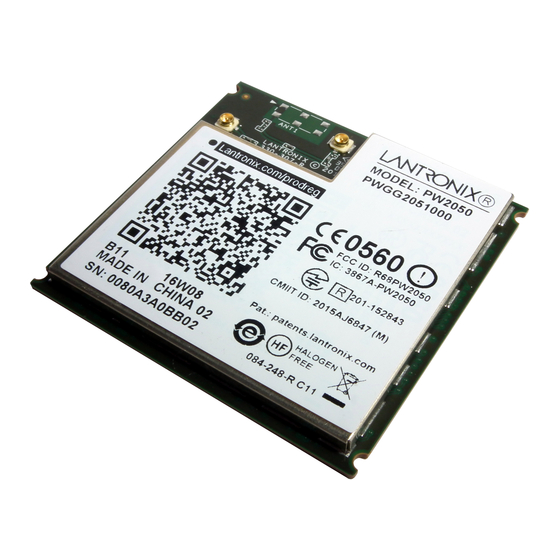
Page 41: Product Information Label
The product information label contains important information about your specific unit, such as its part number, revision, manufacturing date code, product model, country of origin, datamatrix barcode and MAC address. Figure 3-9 PremierWave 2050 Product Label PremierWave® 2050 802.11ac Embedded Wi-Fi® IoT Gateway Integration Guide... -
Page 42: Evaluation Board Schematic
3: PCB Footprint and the PW2050 Dimensions Evaluation Board Schematic Figure 3-10 Evaluation Board Schematic (1 of 7) PremierWave® 2050 802.11ac Embedded Wi-Fi® IoT Gateway Integration Guide... -
Page 43: Figure 3-11 Evaluation Board Schematic (2 Of 7)
3: PCB Footprint and the PW2050 Dimensions Figure 3-11 Evaluation Board Schematic (2 of 7) PremierWave® 2050 802.11ac Embedded Wi-Fi® IoT Gateway Integration Guide... -
Page 44: Figure 3-12 Evaluation Board Schematic (3 Of 7)
3: PCB Footprint and the PW2050 Dimensions Figure 3-12 Evaluation Board Schematic (3 of 7) PremierWave® 2050 802.11ac Embedded Wi-Fi® IoT Gateway Integration Guide... -
Page 45: Figure 3-13 Evaluation Board Schematic (4 Of 7)
3: PCB Footprint and the PW2050 Dimensions Figure 3-13 Evaluation Board Schematic (4 of 7) PremierWave® 2050 802.11ac Embedded Wi-Fi® IoT Gateway Integration Guide... -
Page 46: Figure 3-14 Evaluation Board Schematic (5 Of 7)
3: PCB Footprint and the PW2050 Dimensions Figure 3-14 Evaluation Board Schematic (5 of 7) PremierWave® 2050 802.11ac Embedded Wi-Fi® IoT Gateway Integration Guide... -
Page 47: Figure 3-15 Evaluation Board Schematic (6 Of 7)
3: PCB Footprint and the PW2050 Dimensions Figure 3-15 Evaluation Board Schematic (6 of 7) PremierWave® 2050 802.11ac Embedded Wi-Fi® IoT Gateway Integration Guide... -
Page 48: Figure 3-16 Evaluation Board Schematic (7 Of 7)
3: PCB Footprint and the PW2050 Dimensions Figure 3-16 Evaluation Board Schematic (7 of 7) PremierWave® 2050 802.11ac Embedded Wi-Fi® IoT Gateway Integration Guide...