Table of Contents
Advertisement
Quick Links
Download this manual
See also:
User Manual
Advertisement
Table of Contents

Related Manuals for Lantronix PremierWave XC HSPA+


Summary of Contents for Lantronix PremierWave XC HSPA+
-
Page 1: User Guide
PRELIMINARY DRAFT PremierWave XC HSPA+ User Guide Part Number 900-678-R Revision A May 2013 PRELIMINARY DRAFT... - Page 2 PRELIMINARY DRAFT Copyright & Trademark © 2013 Lantronix, Inc. All rights reserved. No part of the contents of this book may be transmitted or reproduced in any form or by any means without the written permission of Lantronix. Lantronix® registered trademark of Lantronix, Inc. DeviceInstaller and PremierWave© are trademark of Lantronix, Inc.
-
Page 3: Table Of Contents
PRELIMINARY DRAFT Table of Contents List of Figures _____________________________________________________________ 9 List of Tables _____________________________________________________________ 10 1: Using This Guide Purpose and Audience _____________________________________________________ 12 Summary of Chapters ______________________________________________________ 12 Additional Documentation ___________________________________________________ 13 2: Introduction Key Features _____________________________________________________________ 14 Applications ______________________________________________________________ 14 Protocol Support _________________________________________________________ 14 Troubleshooting Capabilities _________________________________________________ 15... - Page 4 PRELIMINARY DRAFT 6: Network Settings Network 1 (eth0) Interface Settings ____________________________________________ 32 To Configure Network Interface Settings ____________________________________ 33 To View Network Interface Status _________________________________________ 33 Network 1 (Link) Settings ___________________________________________________ 34 To Configure Network Link Settings ________________________________________ 34 Network 1 (Failover) _______________________________________________________ 35 To Configure Network 1 Failover Settings ___________________________________ 35 Network 2 (Cellular) Settings ________________________________________________ 35 To Configure Network 2 (Cellular Interface) Settings ___________________________ 36...
- Page 5 PRELIMINARY DRAFT To Configure Tunnel Accept Mode Settings __________________________________ 51 Connect Mode ________________________________________________________ 51 To Configure Tunnel Connect Mode Settings ________________________________ 52 Disconnect Mode ______________________________________________________ 52 To Configure Tunnel Disconnect Mode Settings ______________________________ 53 Modem Emulation ______________________________________________________ 53 To Configure Tunnel Modem Emulation Settings ______________________________ 54 Relay Output _____________________________________________________________ 54 To Configure Relay Settings ______________________________________________ 55 10: Terminal and Host Settings...
- Page 6 PRELIMINARY DRAFT SSH Client Users ______________________________________________________ 68 To Configure SSH Settings ______________________________________________ 69 SSL Settings _____________________________________________________________ 69 Certificate and Key Generation ___________________________________________ 69 To Create a New Credential ______________________________________________ 70 Certificate Upload Settings _______________________________________________71 To Configure an Existing SSL Credential ____________________________________ 71 Trusted Authorities _____________________________________________________ 72 To Upload an Authority Certificate _________________________________________ 72 13: Maintenance and Diagnostics Settings...
- Page 7 PRELIMINARY DRAFT To View Thread Information ______________________________________________ 81 Clock ___________________________________________________________________ 81 To Specify Clock Setting Method __________________________________________ 82 System Settings __________________________________________________________ 82 To Reboot or Restore Factory Defaults _____________________________________ 82 Discovery and Query Port ___________________________________________________ 83 To Configure Discovery _________________________________________________ 83 14: Advanced Settings Email Settings ____________________________________________________________ 84 To View, Configure and Send Email ________________________________________ 84...
- Page 8 PRELIMINARY DRAFT 17: Branding the PremierWave XC HSPA+ Web Manager Customization ________________________________________________ 96 Short and Long Name Customization __________________________________________ 97 To Customize Short or Long Names _______________________________________ 97 Appendix A: Technical Specifications Network _________________________________________________________________ 98 Cellular ______________________________________________________________ 98 Ethernet _____________________________________________________________ 98 Serial Interface ___________________________________________________________ 98 Serial Connector __________________________________________________________ 98 USB Interface ____________________________________________________________ 98...
-
Page 9: List Of Figures
PRELIMINARY DRAFT List of Figures Figure 2-1 PremierWave XC HSPA+Product Label ______________________________________ 17 Figure 3-1 PremierWave XC HSPA+ Top/Front View_____________________________________ 19 Figure 3-2 PremierWave Male DB9 DTE Serial Ports ____________________________________ 20 Figure 3-3 PremierWave Pinout Configuration for RS-232 _________________________________ 20... -
Page 10: List Of Tables
PRELIMINARY DRAFT List of Tables Table 3-6 PremierWave LEDs and Descriptions ________________________________________ 21 Table 3-7 Cellular Signal Strength Indicator ___________________________________________ 21 Table 3-8 Diagnostic LED Indications ________________________________________________ 22 Table 3-9 PremierWave Bottom/Back Panel View _______________________________________ 23 Table 3-10 PremierWave XC HSPA+ Connections (Side) _________________________________ 23 Table 6-1 Network Interface Settings _________________________________________________ 32 Table 6-2 Network 1 (eth0) Link Settings ______________________________________________ 34 Table 6-3 WAN Configuration ______________________________________________________ 37... - Page 11 PRELIMINARY DRAFT Table 12-1 SSH Server Host Keys ___________________________________________________ 66 Table 12-2 SSH Client Known Hosts _________________________________________________ 67 Table 12-3 SSH Server Authorized Users _____________________________________________ 68 Table 12-4 SSH Client Users _______________________________________________________ 68 Table 12-5 Certificate and Key Generation Settings _____________________________________ 70 Table 12-6 Upload Certificate Settings _______________________________________________71 Table 12-7 Trusted Authority Settings ________________________________________________ 72 Table 13-1 File Display Settings ____________________________________________________ 73...
-
Page 12: 1: Using This Guide
Instructions on how to brand your device. HSPA+ Appendix A: Technical Specifications Technical specifications for the device. Appendix C: Technical Support Instructions for contacting Lantronix Technical Support. Appendix D: Binary to Hexadecimal Instructions for converting binary values to hexadecimals. Conversions Appendix B: Compliance Lantronix compliance information. -
Page 13: Additional Documentation
PremierWave XC HSPA+ Quick Instructions for getting the PremierWave up and running. Start Guide DeviceInstaller Online Help Instructions for using the Lantronix Windows-based utility to locate the PremierWave and to view its current settings. PremierWave XC HSPA+ User Guide PRELIMINARY DRAFT... -
Page 14: 2: Introduction
PRELIMINARY DRAFT Introduction PremierWave XC HSPA+ is a multi-port device server offering ethernet and cellular connectivity for remote access and easy management of machines or equipment over the network and across the internet. Key Features Power Supply: 9-30VDC input voltage through locking barrel connector. 12V wall cube ... -
Page 15: Troubleshooting Capabilities
PremierWave and assigning IP addresses and other configurable settings: Web Manager: View and configure all settings easily through a web browser using the Lantronix Web Manager. (See “Configuration Using Web Manager” on page 27.) DeviceInstaller: Configure the IP address and related settings and view current settings on ... -
Page 16: Addresses And Port Numbers
TCP Port 80: HTTP (Web Manager configuration) TCP Port 21: FTP UDP Port 30718: LDP (Lantronix Discovery Protocol) port TCP/UDP Port 10001: Tunnel 1 (see note below) UDP Port 1900 and TCP Port 30179: UPnP ... -
Page 17: Figure 2-1 Premierwave Xc Hspa+Product Label
PRELIMINARY DRAFT 2: Introduction Figure 2-1 PremierWave XC HSPA+Product Label Data Code Part Number Revision Serial Number IMEI Text Country of Origin PremierWave XC HSPA+ User Guide PRELIMINARY DRAFT... -
Page 18: 3: Installation Of Premierwave Xc Hspa
PRELIMINARY DRAFT Installation of PremierWave XC HSPA+ This chapter describes how to install the PremierWave XC HSPA+ device server. It contains the following sections: Package Contents User-Supplied Items Hardware Components Installing the PremierWave XC HSPA+ Package Contents The PremierWave XC HSPA+ package includes the following items: One PremierWave XC HSPA+ device ... -
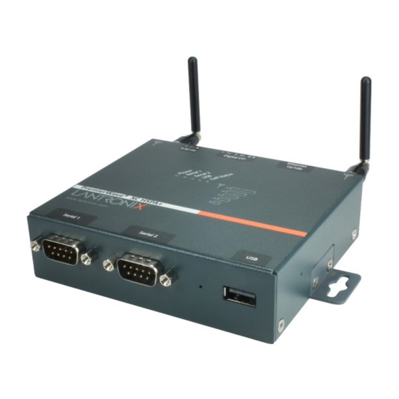
Page 19: Figure 3-1 Premierwave Xc Hspa+ Top/Front View
PRELIMINARY DRAFT 3: Installation of PremierWave XC HSPA+ Figure 3-1 PremierWave XC HSPA+ Top/Front View Signal Strength LEDs Diagnostic The PremierWave has two male DB9 serial ports that support RS-232/422/485. Figure 3-2 shows the front view of the device. The default serial port settings are 9600 baud, 8 bits, no parity, 1 stop bit, no flow control. -
Page 20: Figure 3-2 Premierwave Male Db9 Dte Serial Ports
PRELIMINARY DRAFT 3: Installation of PremierWave XC HSPA+ Figure 3-2 PremierWave Male DB9 DTE Serial Ports Serial Serial Reset Button Port Figure 3-3 PremierWave Pinout Configuration for RS-232 Figure 3-4 PremierWave Pinout Configuration for Full Duplex RS-422/485 (4-wire Figure 3-5 PremierWave Pinout Configuration for Half Duplex RS-422/485 (2-wire) PremierWave XC HSPA+ User Guide PRELIMINARY DRAFT... -
Page 21: Table 3-6 Premierwave Leds And Descriptions
PRELIMINARY DRAFT 3: Installation of PremierWave XC HSPA+ Ethernet LEDs The Ethernet Port has two LEDs that indicate the status of the connection as follows: Left LED Green ON 100Mbps Link Green Blink 100Mbps Activity Amber ON 10Mbps Link ... -
Page 22: Table 3-8 Diagnostic Led Indications
PRELIMINARY DRAFT 3: Installation of PremierWave XC HSPA+ Table 3-8 Diagnostic LED Indications Fault Conditions Blink Pattern No Ethernet link when eth0 is enabled Long, long, short, short, 2 seconds off, continuous No cellular link (no BSSID detected) when wlan0 is Long, long, long, short, short, 2 seconds off, enabled continuous... -
Page 23: Back Panel
PRELIMINARY DRAFT 3: Installation of PremierWave XC HSPA+ Back Panel On the PremierWave is a Power 1 Plug and RJ-45 Ethernet port as shown in Table 3-9. Table 3-9 PremierWave Bottom/Back Panel View Relay Relay Antenna Ethernet Terminal Block Barrel Antenna (RX Diversity) Power (6-pin) Plug... -
Page 24: Figure 3-11 Premierwave Dimensions In Inches (In)
PRELIMINARY DRAFT 3: Installation of PremierWave XC HSPA+ Perform the following steps to install your device: 1. With the power unplugged, insert your SIM card. 2. Connect an RJ-45 Ethernet cable between the unit and your Ethernet network. 3. Connect the antennas to the SMA connectors on the back. Do note that the safe distance due to RF exposure from antenna is 20 cm. -
Page 25: 4: Using Deviceinstaller
Using DeviceInstaller This chapter covers the steps for locating a PremierWave XC HSPA+ unit and viewing its properties and device details. DeviceInstaller is a free utility program provided by Lantronix that discovers, configures, upgrades and manages Lantronix Device Servers. Notes: For instructions on using DeviceInstaller to configure the IP address and related ... - Page 26 Shows the device family type as “PremierWave”. Short Name Shows “premierwave_xc_hspa” by default. Long Name Shows “Lantronix PremierWave XC HSPA+” by default. Type Shows the device type as “PremierWave XC HSPA+””. Shows the PremierWave ID embedded within the unit. Hardware Address Shows the PremierWave hardware (MAC) address.
-
Page 27: 5: Configuration Using Web Manager
DeviceInstaller window. To access Web Manager, perform the following steps: 1. Open a standard web browser. Lantronix supports the latest version of Internet Explorer, Mozilla Suite, Mozilla Firefox, Safari, Chrome or Opera. 2. Enter the IP address or hostname of the PremierWave in the address bar. The IP address may have been assigned manually using DeviceInstaller (see the PremierWave Quick Start Guide) or automatically by DHCP. -
Page 28: Device Status Page
PRELIMINARY DRAFT 5: Configuration Using Web Manager Device Status Page The Device Status page is the first to appear after you log into Web Manager. The Device Status page also appears when you click Status in Web Manager. Figure 5-1 PremierWave XC HSPA+ Home Pages Note: The Logout button is available on any web page. -
Page 29: Web Manager Components
PRELIMINARY DRAFT 5: Configuration Using Web Manager Web Manager Components The layout of a typical Web Manager page is below. Figure 5-2 Components of the Web Manager Page Logout Items to Links to button configure subpages Header Menu Bar Footer Information Configuration and/or Status Area and Help Area... -
Page 30: Navigating Web Manager
The footer appears at the very bottom of the page. It contains copyright information and a link to the Lantronix home page. Navigating Web Manager The Web Manager provides an intuitive point-and-click interface. A menu bar on the left side of each page provides links you can click to navigate from one page to another. - Page 31 PRELIMINARY DRAFT 5: Configuration Using Web Manager Web Manager Page Description (continued) Page Discovery Allows you to view and modify the configuration and statistics for device discovery. Shows the current configuration of the DNS subsystem and the DNS cache. Email Shows email statistics and lets you clear the email log, configure email settings, and send an email.
-
Page 32: 6: Network Settings
PRELIMINARY DRAFT Network Settings The Network Settings show the status of the Ethernet interface/link and let you configure the settings on the device. Interface settings are related to the configuration of the IP and related protocols. Link settings are related to the physical link connection, which carries the IP traffic. The PremierWave contains one network interface. -
Page 33: To Configure Network Interface Settings
PRELIMINARY DRAFT 6: Network Settings Network Interface Description Settings (continued) Default Gateway Enter the IP address of the router for this network. Note: This setting will be used if Static IP is active (both DHCP and BOOTP are Disabled). Hostname Enter the hostname for the interface. -
Page 34: Network 1 (Link) Settings
PRELIMINARY DRAFT 6: Network Settings To view Ethernet (eth0) Status, click Network on the menu and select Network 1 -> Interface -> Status. Network 1 (Link) Settings Physical link parameters can be configured for an Ethernet (eth0) Network Interface (see Table 6-2). -
Page 35: Network 1 (Failover)
PRELIMINARY DRAFT 6: Network Settings Network 1 (Failover) PremierWave XC HSPA+ provides basic Ethernet to Cellular failover, in the form of a "dead remote host reachability" mechanism (essentially a ping against a known host). If the remote host is determined to be not reachable, the device will failover to the cellular interface. If the remote host is determined to be reachable, the device will failback to the Ethernet interface. -
Page 36: To Configure Network 2 (Cellular Interface) Settings
PRELIMINARY DRAFT 6: Network Settings Network 2 (Cellular Description Interface) Settings Connection Mode The Always On connection mode keeps the device always connected to the cellular network. The On Demand connection mode leaves the link quiescent until an application attempts to make use of the cellular network connection. Be aware that in this mode, the first attempt to initiate a connection from the device server may fail, since a new IP address may need to be negotiated. -
Page 37: To Configure Link Settings
PRELIMINARY DRAFT 6: Network Settings To Configure Link Settings Using Web Manager To modify network 2 cellular interface information, click Network on the menu and select Network 2 > Link > Configuration. Using the CLI To enter the link command level: enable -> if 2 -> link ... -
Page 38: To Configure Gateway Wan Settings
PRELIMINARY DRAFT 6: Network Settings To Configure Gateway WAN Settings Using Web Manager To modify gateway WAN information, click Gateway on the menu and select Configuration > WAN. Using the CLI To enter the gateway command level: enable -> config -> gateway ... -
Page 39: Static Routes
PRELIMINARY DRAFT 6: Network Settings Using the CLI To enter the gateway command level: enable -> config -> gateway -> port forwarding rule <number> Using XML Include in your file: <configgroup name="gateway"> <configitem name="port forwarding" instance="<number>"> Static Routes Allows the user to add routes to the device routing table. -
Page 40: Dhcp Server
PRELIMINARY DRAFT 6: Network Settings DHCP Server Allows the user to configure the device as a DHCP server. Table 6-7 DHCP Settings DHCP Settings Description State Enable or Disable the DHCP server Enabled: DHCP server is enabled Disabled: DHCP server is disabled. ... -
Page 41: 7: Cellular
PRELIMINARY DRAFT Cellular The Cellular page displays the configuration and status for the Cellular module. Cellular Settings Description PIN Lock Enable to prevent unauthorized use of the SIM card. Enter PIN combination to enable PIN Lock. Caution: If you enter the PIN incorrectly 3 times, the SIM card will lock, and you will need a PIN Unblocking Key (PUK) to unlock your SIM card. -
Page 42: 8: Action Settings
PRELIMINARY DRAFT Action Settings Actions can be configured for alarms and reports available in the PremierWave. Alarms and Reports PremierWave XC HSPA+ updates the action settings page to display and configure the alarms. The following alarm and report acations are available in PremierWave XC HSPA+: Eth0 Link State Change ... -
Page 43: To Configure Action Settings
PRELIMINARY DRAFT 8: Action Settings Action Settings Description HTTP Post Use HTTP Post post to configured HTTP server. The URL appears behind the HTTP server IP address or hostname. E.g. http://some_http_server/some_url The IP Address or hostname is the HTTP server to connect to. Port number is the port which HTTP server is listening on. -
Page 44: Digital Input
PRELIMINARY DRAFT 8: Action Settings Digital Input Table 8-2 contain additional configuration options for Digital Input 1 and Digital Input 2 settings: Table 8-2 Digital Input Settings Digital Input Settings Description Title Fill in Title to customize how the digital input status will appear in the CLI, Web Manager, and XML status. -
Page 45: 9: Line And Tunnel Settings
PRELIMINARY DRAFT Line and Tunnel Settings The PremierWavehas two tunnels through which you may view statistics or configure the Accept Mode. The Modbus configuration page allows configuration of Modbus servers listening on the TCP ports. The PremierWave contains two lines . All lines use standard RS232/RS485 serial ports. -
Page 46: To Configure Line Settings
PRELIMINARY DRAFT 9: Line and Tunnel Settings Line Settings Description (continued) Data Bits Set the number of data bits for the Line. The default is 8. Stop Bits Set the number of stop bits for the Line. The default is 1. Flow Control Set the flow control for the Line. -
Page 47: To View Line Statistics
PRELIMINARY DRAFT 9: Line and Tunnel Settings Using Web Manager To configure a specific line, click Line in the menu and select Line 1 -> Configuration (Table 9-1). To configure a specific line in Command Mode, click Line in the menu and select Line 1 -> ... -
Page 48: To Configure Tunnel Serial Settings
PRELIMINARY DRAFT 9: Line and Tunnel Settings Table 9-3 Tunnel Serial Settings Tunnel Serial Description Settings Line Settings Line Settings information here is display only. Go to the section, To Configure Line Settings to modify these settings. Protocol Protocol information here is display only. Go to the section, To Configure Line Settings to modify these settings. -
Page 49: To Configure Tunnel Packing Mode Settings
PRELIMINARY DRAFT 9: Line and Tunnel Settings Tunnel Packing Mode Description Settings (continued) Timeout Set the timeout value, in milliseconds, after the first character is received on the serial line, before data is sent on the network. Valid range is 1 to 30000 milliseconds. - Page 50 PRELIMINARY DRAFT 9: Line and Tunnel Settings Tunnel Accept Mode Description Settings (continued) Local Port Set the port number for use as the network local port. The default local port number: Tunnel 1 : 10001 Tunnel 2 : 10002 ...
-
Page 51: To Configure Tunnel Accept Mode Settings
PRELIMINARY DRAFT 9: Line and Tunnel Settings To Configure Tunnel Accept Mode Settings Using Web Manager To configure the Accept Mode for a specific tunnel, click Tunnel in the menu and select Tunnel 1 -> Accept Mode. Using the CLI To enter Tunnel 1 Accept Mode command level: enable ->... -
Page 52: To Configure Tunnel Connect Mode Settings
PRELIMINARY DRAFT 9: Line and Tunnel Settings Tunnel Connect Mode Description Settings (continued) Host 1 Click on the displayed information to expand it for editing. If <None> is displayed, clicking it will allow you to configure a new host. At least one Host is required to enable Connect Mode as this information is necessary to connect to that host. -
Page 53: To Configure Tunnel Disconnect Mode Settings
PRELIMINARY DRAFT 9: Line and Tunnel Settings Table 9-7 Tunnel Disconnect Mode Settings Tunnel Disconnect Description Mode Settings Stop Character Enter the Stop Character which when received on the Serial Line, disconnects the tunnel. The Stop Character may be designated as a single printable character or as a control character. -
Page 54: To Configure Tunnel Modem Emulation Settings
PRELIMINARY DRAFT 9: Line and Tunnel Settings Tunnel Modem Description Emulation Settings (continued) Echo Commands Set whether characters read on the Serial Line will be echoed, while the Line is in Modem Command Mode. Choices are: Enabled Disabled (default) Verbose Response Set whether Modem Response Codes are sent out on the Serial Line. -
Page 55: Relay Output
PRELIMINARY DRAFT 9: Line and Tunnel Settings Relay Output Note: When relay is energized/turned on, the relay is closed connecting both relay ports on the IO connector through the relay. When the relay is turned off, the signal path is open, disconnecting the relay ports on the IO connector. -
Page 56: 10: Terminal And Host Settings
PRELIMINARY DRAFT 10: Terminal and Host Settings Predefined connections are available via telnet, ssh, or a serial port. A user can choose one of the presented options and the device automatically makes the predefined connection. Either the Telnet, SSH, or serial port connection can present the CLI or the Login Connect Menu. By default, the CLI is presented when the device is accessed. -
Page 57: To Configure The Terminal Network Connection
PRELIMINARY DRAFT 10: Terminal and Host Settings To Configure the Terminal Network Connection Using Web Manager To configure the Terminal on Network, click Terminal on the menu and select Network -> Configuration. To configure the Terminal on Network, click Line 1 on the menu and select Network -> ... -
Page 58: Host Configuration
PRELIMINARY DRAFT 10: Terminal and Host Settings Host Configuration Table 10-2 Host Configuration Host Settings Description Name Enter a name for the host. This name appears on the Login Connect Menu. To leave a host out of the menu, leave this field blank. Protocol Select the protocol to use to connect to the host. -
Page 59: 11: Services Settings
PRELIMINARY DRAFT 11: Services Settings DNS Settings This section describes the active run-time settings for the domain name system (DNS) protocol. The primary and secondary DNS addresses come from the active interface. The static addresses from the Network Interface configuration settings may be overridden by DHCP. Note: blue text in the XML command strings of this chapter are to be replaced with... -
Page 60: To Configure Ftp Settings
PRELIMINARY DRAFT 11: Services Settings To Configure FTP Settings Using Web Manager To configure FTP, click FTP in the menu. Using the CLI To enter the FTP command level: enable -> config -> ftp Using XML Include in your file: ... -
Page 61: Http Settings
PRELIMINARY DRAFT 11: Services Settings Using XML Include in your file: <configgroup name=”syslog”> HTTP Settings Hypertext Transfer Protocol (HTTP) is the transport protocol for communicating hypertext documents on the Internet. HTTP defines how messages are formatted and transmitted. It also defines the actions web servers and browsers should take in response to different commands. -
Page 62: To Configure Http Settings
PRELIMINARY DRAFT 11: Services Settings HTTP Settings (continued) Description Log Format Set the log format string for the HTTP server. Follow these Log Format rules: %a - remote IP address (could be a proxy) %b - bytes sent excluding headers ... -
Page 63: To Configure Http Authentication
PRELIMINARY DRAFT 11: Services Settings To Configure HTTP Authentication Using Web Manager To configure HTTP Authentication, click HTTP in the menu and select Authentication. Using the CLI To enter the HTTP command level: enable -> config -> http Using XML Include in your file: ... -
Page 64: Snmp Settings
PRELIMINARY DRAFT 11: Services Settings SNMP Settings Simple Network management Protocol (SNMP) settings may be viewed and configured in this section. Table 11-7 SNMP Settings RSS Settings Description System Location Specify a system location for the SNMP setting. Primary Destination Specify SNMP trap primary destination. -
Page 65: Outbound Sms
PRELIMINARY DRAFT 11: Services Settings Outbound SMS Table 11-9 Outbound SMS Settings Outbound SMS Settings Description Message Center Default Displays the Message Center number as configured in the SIM. Number Message Center Enter a number to override the existing Message Center number. Override Number Band Select a band from the drop-down menu:... -
Page 66: 12: Security Settings
PRELIMINARY DRAFT 12: Security Settings The PremierWave XC HSPA+ device supports Secure Shell (SSH) and Secure Sockets Layer (SSL). SSH is a network protocol for securely accessing a remote device. SSH provides a secure, encrypted communication channel between two hosts over a network. It provides authentication and message integrity services. -
Page 67: Ssh Client Known Hosts
PRELIMINARY DRAFT 12: Security Settings RSS Settings Description (continued) Public Key Enter the path and name of the existing public key you want to upload. In WebManager, you can also browse to the public key to be uploaded. Key Type Select a key type to use for the new key: ... -
Page 68: Ssh Client Users
PRELIMINARY DRAFT 12: Security Settings Table 12-3 SSH Server Authorized Users RSS Settings Description Username Enter a new username or edit an existing one. Password Enter a new password or edit an existing one. Public RSA Key Enter the path and name of the existing public RSA key you want to use with this user. -
Page 69: To Configure Ssh Settings
PRELIMINARY DRAFT 12: Security Settings RSS Settings Description (continued) Bit Size Select the bit length of the new key: 1024 Using a larger Bit Size takes more time to generate the key. Approximate times are: 1 second for a 512 bit RSA key ... -
Page 70: To Create A New Credential
PRELIMINARY DRAFT 12: Security Settings Table 12-5 Certificate and Key Generation Settings Certificate Generation Description Settings Country (2 Letter Code) Enter the 2-letter country code to be assigned to the new self-signed certificate. Examples: US for United States and CA for Canada State/Province Enter the state or province to be assigned to the new self-signed certificate. -
Page 71: Certificate Upload Settings
PRELIMINARY DRAFT 12: Security Settings Certificate Upload Settings SSL certificates identify the PremierWave to peers. Certificate and key pairs can be uploaded to the PremierWave through either the CLI or XML import mechanisms. Certificates can be identified on the PremierWave by a name provided at upload time. Table 12-6 Upload Certificate Settings Upload Description... -
Page 72: Trusted Authorities
PRELIMINARY DRAFT 12: Security Settings Trusted Authorities One or more authority certificates are needed to verify a peer's identity. These certificates do not require a private key. Table 12-7 Trusted Authority Settings Trusted Authorities Description Settings Authority SSL authority certificate. RSA or DSA certificates are allowed. -
Page 73: 13: Maintenance And Diagnostics Settings
PRELIMINARY DRAFT 13: Maintenance and Diagnostics Settings Filesystem Settings Use the file system to list, view, add, remove, and transfer files. The PremierWave uses a flash file system to store files. File Display It is possible to view the list of existing files, and to view their contents in the ASCII or hexadecimal formats. -
Page 74: File Modification
PRELIMINARY DRAFT 13: Maintenance and Diagnostics Settings File Modification The PremierWave allows for the creation and removal of files on its filesystem. Table 13-2 File Modification Settings File Modification Description Commands Removes the specified file from the file system. touch Creates the specified file as an empty file. -
Page 75: To Transfer Or Modify Filesystem Files
PRELIMINARY DRAFT 13: Maintenance and Diagnostics Settings To Transfer or Modify Filesystem Files Using Web Manager To create a new file or directory, upload an existing file, copy or move a file, click Filesystem in the menu and select Browse. Using the CLI To enter the Filesystem command level: ... -
Page 76: Icmp Settings
PRELIMINARY DRAFT 13: Maintenance and Diagnostics Settings ICMP Settings Table 13-5 ICMP Network Stack Settings Protocol Stack Description ICMP Settings State The State selection is used to turn on/off processing of ICMP messages. This includes both incoming and outgoing messages. Choose Enabled or Disabled. -
Page 77: Smtp Settings
PRELIMINARY DRAFT 13: Maintenance and Diagnostics Settings SMTP Settings Table 13-7 SMTP Network Stack Settings Protocol Stack SMTP Description Settings From Address Enter the From Address here. This is an email address and is required. If you wish to direct oubtound email messages through a mail server, put your client email address here. -
Page 78: Diagnostics
PRELIMINARY DRAFT 13: Maintenance and Diagnostics Settings Diagnostics The PremierWave has several tools for diagnostics and statistics. Various options allow for the configuration or viewing of IP socket information, ping, traceroute, memory, and processes. Hardware To View Hardware Information Using Web Manager To view hardware information, click Diagnostics in the menu and select Hardware. -
Page 79: To Ping A Remote Host
PRELIMINARY DRAFT 13: Maintenance and Diagnostics Settings To Ping a Remote Host Using Web Manager To ping a Remote Host, click Diagnostics in the menu and select Ping. Using the CLI To enter the command level: enable, ping <host> <count> <timeout> ... -
Page 80: To Configure The Diagnostic Log Output
PRELIMINARY DRAFT 13: Maintenance and Diagnostics Settings Max Length Set the maximum length of the log.txt file. Note: This setting becomes available when Filesystem is selected. To Configure the Diagnostic Log Output Using Web Manager To configure the Diagnostic Log output, click Diagnostics in the menu and select Log. ... -
Page 81: Threads
PRELIMINARY DRAFT 13: Maintenance and Diagnostics Settings Using the CLI To enter the command level: enable, show processes Using XML Include in your file: <statusgroup name=”processes”> Threads The PremierWave Threads information shows details of threads in the ltrx_evo task which can be useful for technical experts in debugging. -
Page 82: To Specify Clock Setting Method
PRELIMINARY DRAFT 13: Maintenance and Diagnostics Settings To Specify Clock Setting Method Using Web Manager To view thread information, click Clock in the menu. Using the CLI To enter the command level: enable -> config -> clock Using the XML Include in your file: <configgroup name="clock">... -
Page 83: Discovery And Query Port
PRELIMINARY DRAFT 13: Maintenance and Diagnostics Settings Using XML Include in your file: <configgroup name=”xml import control”> Discovery and Query Port The current statistics and configuration options for device discovery, including Query Port are available for the PremierWave. Table 13-13 Discovery Settings Discovery Description Query Port Server... -
Page 84: 14: Advanced Settings
PRELIMINARY DRAFT 14: Advanced Settings Email Settings View and configure email alerts relating to events occurring within the system. Email Configuration Table 14-1 Email – Configuration Description Settings Configure SMTP Click this link to configure SMTP: SMTP Settings (on page 77). -
Page 85: Command Line Interface Settings
PRELIMINARY DRAFT 14: Advanced Settings Using the CLI To enter Email command level: enable -> email 1 Using XML Include in your file: <configgroup name=”email” instance=”1”> Command Line Interface Settings The Command Line Interface settings allow you to control how users connect to and interact with the PremierWave's command line. -
Page 86: Telnet Settings
PRELIMINARY DRAFT 14: Advanced Settings Telnet Settings The telnet settings control CLI access to the PremierWave over the Telnet protocol. Table 14-3 Telnet Settings Telnet Settings Description Telnet State Enable or Disable CLI access via telnet Telnet Port Enter an alternative Telnet Port to override the default used by the CLI server. Blank the field to restore the default. -
Page 87: To Configure Ssh Settings
PRELIMINARY DRAFT 14: Advanced Settings To Configure SSH Settings Using Web Manager To configure SSH settings, click CLI in the menu and select Configuration. Using the CLI To enter the SSH command level: enable -> config -> cli -> ssh ... -
Page 88: To Export Configuration In Xml Format
PRELIMINARY DRAFT 14: Advanced Settings XML Export Configuration Description Settings (continued) Groups to Export Check the configuration groups that are to be exported to the XML configuration record. The group list should be comma delimited and encased in double quotes. The list of available groups can be viewed with the “xcr list”... -
Page 89: Xml: Import Configuration
PRELIMINARY DRAFT 14: Advanced Settings Using XML Not applicable. XML: Import Configuration Here you can import a system configuration from an XML file. The XML data can be imported from a file on the file system or pasted into a CLI session. The groups to import can be specified at the command line, the default is all groups. - Page 90 PRELIMINARY DRAFT 14: Advanced Settings Using XML Not applicable. PremierWave XC HSPA+ User Guide PRELIMINARY DRAFT...
-
Page 91: 15: Security In Detail
PRELIMINARY DRAFT 15: Security in Detail Public Key Infrastructure Public key infrastructure (PKI) is based on an encryption technique that uses two keys: a public key and private key. Public keys can be used to encrypt messages which can only be decrypted using the private key. -
Page 92: Obtaining Certificates
PRELIMINARY DRAFT 15: Security in Detail through any number of intermediate authorities, ultimately to the agent that needs to prove its authenticity. Obtaining Certificates Signed certificates are typically obtained from well-known CAs, such as VeriSign. This is done by submitting a certificate request for a CA, typically for a fee. The CA will sign the certificate request, producing a certificate/key combo: the certificate contains the identity of the owner and the public key, and the private key is available separately for use by the owner. -
Page 93: Steel Belted Radius
PRELIMINARY DRAFT 15: Security in Detail Steel Belted RADIUS Steel Belted RADIUS is a commercial RADIUS server from Juniper Networks that provides a GUI administration interface. It also provides a certificate request and self-signed certificate generator. The self-signed certificate has extension .sbrpvk and is in the PKCS12 format. OpenSSL can convert this into a PEM format certificate and key: openssl pkcs12 -in sbr_certkey.sbrpvk -nodes -out sbr_certkey.pem The sbr_certkey.pem file contains both certificate and key. -
Page 94: 16: Updating Firmware
PRELIMINARY DRAFT 16: Updating Firmware Obtaining Firmware Obtain the most up-to-date firmware and release notes for the unit from the Lantronix Web site (www.lantronix.com/support/downloads/) or by using anonymous FTP (ftp://ftp.lantronix.com/). Loading New Firmware through Web Manager Upload the firmware using the device web manager System page. -
Page 95: Loading New Firmware Through Ftp
PRELIMINARY DRAFT 16: Updating Firmware device will automatically reboot afterwards. 6. Close and reopen the web manager internet browser to view the device’s updated web pages. Note: You may need to increase HTTP Max Bytes in some cases where the browser is sending data aggressively within TCP windows size limit when file (including firmware upgrade) is uploaded from webpage. -
Page 96: 17: Branding The Premierwave Xc Hspa
PRELIMINARY DRAFT 17: Branding the PremierWave XC HSPA+ This chapter describes how to brand your PremierWave by using Web Manager and Command Line Interface (CLI). It contains the following sections on customization: Web Manager Customization Short and Long Name Customization ... -
Page 97: Short And Long Name Customization
PRELIMINARY DRAFT 17: Branding the PremierWave XC HSPA+ Short and Long Name Customization You can customize the short and long names in your PremierWave. The names display in the CLI show command and in the System web page in the Current Configuration table. The short name is used for the show command. -
Page 98: Appendix A: Technical Specifications
PRELIMINARY DRAFT Appendix A: Technical Specifications Network Cellular UMTS/HSPA+ (850/800/900/1900/2100 MHz) GSM/GPRS/EDGE (850/900/1800/1900 MHz) Transfer Rates - up to 14.4 Mbps (downlink), up to 7.2Mbps (uplink) 1 Secure SIM Slot 2 x Omni-Directional Penta-band Antennas ... -
Page 99: Usb Connector
PRELIMINARY DRAFT USB Connector 1 x USB Type A Host Connector (USB 2.0) I/O Interface Input Connection: Sensors/Events Voltage acceptance: 0 to 30 VDC Digital input event: User configurable Optical: 1.5 KV Output Software: Turn Relay Output ON and OFF ... -
Page 100: Management
CLI (over serial ports, Telnet, or SSH) XML Configuration Records via CLI or FTP Supports SNMP version 2c Software Lantronix Device Server Application Suite DeviceInstaller. Power Input Voltage: 9-30 VDC Power Consumption: 3.6 Watts (typical) ... -
Page 101: Dimensions
PRELIMINARY DRAFT Dimensions Size: 9.4 cm (3.7 in) L x 10.9 cm (4.3 in) W x 3.0 cm (1.2 in) H Weight: 0.44 kg (1.0 lb) Warranty 5-Year Limited PremierWave XC HSPA+ User Guide PRELIMINARY DRAFT... -
Page 102: Appendix B: Compliance
PRELIMINARY DRAFT Appendix B: Compliance (According to ISO/IEC Guide 17050-1, 17050-2 and EN 45014) Manufacturer's Name & Address: Lantronix, Inc. 167 Technology Drive, Irvine, CA 92618 USA Product Name Model: PremierWave XC HSPA+ This device complies with part 15 of the FCC Rules. Operation is subject to the following two conditions: (1) This device may not cause harmful interference, and (2) this device must accept any interference received, including interference that may cause undesired operation. - Page 103 PRELIMINARY DRAFT Appendix B: Compliance Conforms to the following standards or other normative documents: Emissions FCC 15.107:2013 FCC 15.109:2013 FCC 22H:2011 FCC 24E:2011 RSS-132:2005 RSS-133:2009 EN 301 489-24 EN 301 489-7 EN 301 511 (GSM & EDGE) ...
- Page 104 Manufacturer's Contact: Lantronix, Inc. 167 Technology Drive, Irvine, CA 92618 USA Tel: 949-453-3990 Fax: 949-450-7249 RoHS Notice All Lantronix products in the following families are China RoHS-compliant and free of the following hazardous substances and elements: Lead (Pb)
-
Page 105: Appendix C: Technical Support
Check our online knowledge base or send a question to Technical Support at http://www.lantronix.com/support. Technical Support Europe, Middle East, Africa Phone: +33 13 930 4172 Email: eu_techsupp@lantronix.com or eu_support@lantronix.com Firmware downloads, FAQs, and the most up-to-date documentation are available at http://www.lantronix.com/support When you report a problem, please provide the following information: Your name, and your company name, address, and phone number ... -
Page 106: Appendix D: Binary To Hexadecimal Conversions
PRELIMINARY DRAFT Appendix D: Binary to Hexadecimal Conversions Many of the unit's configuration procedures require you to assemble a series of options (represented as bits) into a complete command (represented as a byte). The resulting binary value must be converted to a hexadecimal representation. Use this chapter to learn to convert binary values to hexadecimals or to look up hexadecimal values in the tables of configuration options. - Page 107 PRELIMINARY DRAFT Figure D-2 Windows Scientific Calculator 4. Click Hex. The hexadecimal value appears. Figure D-3 Hexadecimal Values in the Scientific Calculator PremierWave XC HSPA+ User Guide PRELIMINARY DRAFT...
-
Page 108: Appendix E: Usb-Cdc-Acm Device Driver File For Windows Hosts
PRELIMINARY DRAFT Appendix E: USB-CDC-ACM Device Driver File for Windows Hosts The following file may be used to enable Windows to recognize the USB-CDC-ACM connection to the PremierWave's USB Device port. Create the linux-cdc-acm.inf file on the Windows host somewhere using the contents provided below. - Page 109 PRELIMINARY DRAFT Appendix E: USB-CDC-ACM Device Driver File for Windows Hosts ;----------------------------------------------------------------------- Vista-64bit Sections ;----------------------------------------------------------------------- [DriverInstall.NTamd64] include=mdmcpq.inf CopyFiles=DriverCopyFiles.NTamd64 AddReg=DriverInstall.NTamd64.AddReg [DriverCopyFiles.NTamd64] USBSER.sys,,,0x20 [DriverInstall.NTamd64.AddReg] HKR,,DevLoader,,*ntkern HKR,,NTMPDriver,,USBSER.sys HKR,,EnumPropPages32,,"MsPorts.dll,SerialPortPropPageProvider" [DriverInstall.NTamd64.Services] AddService=usbser, 0x00000002, DriverService.NTamd64 [DriverService.NTamd64] DisplayName=%SERVICE% ServiceType=1 StartType=3 ErrorControl=1 ServiceBinary=%12%\USBSER.sys ;----------------------------------------------------------------------- Vendor and Product ID Definitions ;----------------------------------------------------------------------- ;...