Advertisement
Table of Contents
- 1 Table of Contents
- 2 Step 1- Remove Track Supports
- 3 Step 2- Table Assembly
- 4 Step 3- End Leg Assembly
- 5 Step 4- Middle Leg Assembly
- 6 Step 6- Support Rail Assembly
- 7 Step 7- Track Assembly
- 8 Step 8- Ratchet Stop Assembly
- 9 Step 9- Pole Bracket Assembly
- 10 Step 12- Batting Bar Bracket Assembly
- 11 Step 13- Pole to Frame Assembly
- 12 Step 14- Rubber End Cap Assembly
- 13 Step 15- Bungee Clamp Assembly
- 14 Step 16- Hook & Loop Tape on Pole Assemblies
- 15 Step 17- Attach Leaders
- 16 Step 18- Adjusting Frame Height and Leveling
- Download this manual
Advertisement
Table of Contents

Related Manuals for Baby Lock Kinetic Frame


Summary of Contents for Baby Lock Kinetic Frame
-
Page 2: Table Of Contents
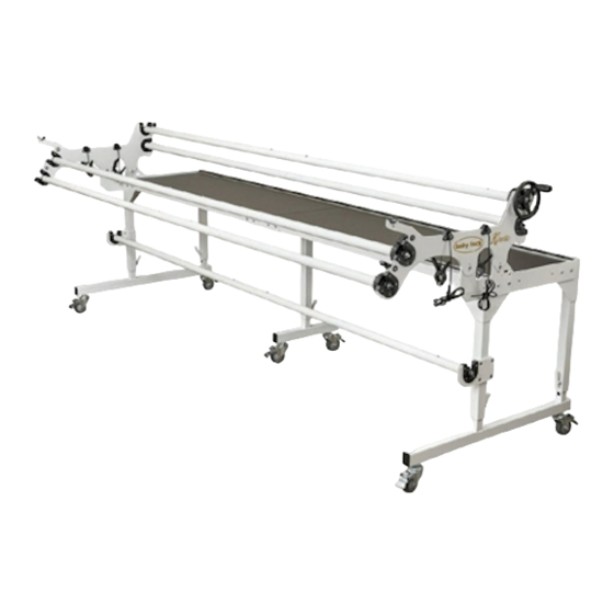
Step 18- Adjusting Frame Height and Leveling What’s Included Your Baby Lock Kinetic Frame is delivered in three separate boxes. Upon opening, please check immediately to see if you have received the items listed in the Parts and Hardware lists found on pages 3, 4 and 5. - Page 3 Baby Lock Kinetic Frame Parts & Hardware List Left Pole Bracket Right Pole Bracket Assembly (1) Assembly (1) QF05314-100 (Comes with latches not Box 2 assembled) Pole Section, 5-foot (10) Pole Coupler (5) QF05314-200 QF05300-701 QF09318-702 Box 2 Box 3...
- Page 4 QF09318-202 QF09318-105 QF09318-106 Baby Lock Kinetic Frame Parts & Hardware List QF09318-204 RATCHET STOP MOUNT QF09318-105 SHING RAIL BEARING SNAP RAIL BEARING SNAP COVER CONNECTOR BOLT Fig. 10-2 QF09318-713 QF09318-705 8-703 HAND WHEEL COLLAR V-GROOVE BEARING POLE END Upper Middle Leg (1)
- Page 5 Baby Lock Kinetic Frame Parts & Hardware List Pole End Assembly (7) Pole End Assembly with Pole End Assembly with Short Bolt (2) Long Bolt (1) QF09326 Box 2 QF09320 QF09321 Box 2 Box 2 Hand Wheel Assembly (1) QF09325...
-
Page 6: Step 1- Remove Track Supports
(Fig. 1-1) (Fig. 1-2). Leave the table sections face down for Step 2-1. NOTE: When removing the track supports, keep them in the same position and orientation to ensure perfect alignment when they are replaced. Baby Lock Kinetic Frame Assembly Instructions... -
Page 7: Step 2- Table Assembly
(Fig. 2-1) 2-3: Finger-tighten two (2) M8x16mm QF09318-07 through the top of eachtable splice. 2-4: Pull the two (2) table sections as close together as possible to remove gap. Baby Lock Kinetic Frame Assembly Instructions... - Page 8 (2) M8x24mm at the end. Lightly M8x25mm M8x16mm QF09318-07 tighten for now with the 5mm Allen wrench. QF09318-06 front and rear at end Baby Lock Kinetic Frame Assembly Instructions...
-
Page 9: Step 3- End Leg Assembly
37-inch floor to quilt plane Two notches showng 36-inch floor to quilt plane One notch showing 35-inch floor to quilt plane notches In first notch up 34-inch floor to quilt plane Bottom 33-inch floor to quilt plane Baby Lock Kinetic Frame Assembly Instructions... - Page 10 3-4: Thread a leveling glide into each end of the corner leg assemblies, leaving about 1/2” of the threads exposed to make it easier to level the frame later. (Fig. 3-5 and Detail 3-5) Baby Lock Kinetic Frame Assembly Instructions...
- Page 11 5mm Allen wrench. Important note: It is recommended the latch be towards the rear of the frame as shown so the latch will not interfere with the batting on the batting storage pole. Baby Lock Kinetic Frame Assembly Instructions...
-
Page 12: Step 4- Middle Leg Assembly
Note: It is easier to raise the frame than lower it once the frame is set upright. (Fig. 4-2) 4-3: Thread a leveling glide into each end of the middle leg assembly. (Detail 4-2) Latch to rear of frame as shown Baby Lock Kinetic Frame Assembly Instructions... - Page 13 Care should be taken with the legs until they are fully tightened. (Fig. 5-1) 5-1: With the help of a second person, lift the frame into an upright position. Baby Lock Kinetic Frame Assembly Instructions...
-
Page 14: Step 6- Support Rail Assembly
(4) screws at the upper corner legs into the frame. (Fig. 6-2) 6-4: Repeat steps 6-1 through 6-3 to attach the remaining support rail to the other end of Tighten these M8x16mm the frame. QF09318-07 at each corner in Step 6-3. Baby Lock Kinetic Frame Assembly Instructions... -
Page 15: Step 7- Track Assembly
7-4: Insert a coupler into one prepared end of one track support section up to the stop screw. Thread an M5x8mm QF09318-304 into the first and second hole and lightly tighten as shown in Fig. 7-2. Baby Lock Kinetic Frame Assembly Instructions... - Page 16 This table. Fully tighten the screws in the back track shoulder is to be placed toward the inside of only for now. the table over the edge of the black plastic tabletop. (Fig. 7-4) Baby Lock Kinetic Frame Assembly Instructions...
- Page 17 Finally, fully tighten the front track 7-10: screws to the table. Baby Lock Kinetic Frame Assembly Instructions...
-
Page 18: Step 8- Ratchet Stop Assembly
(Figure when finished. 8-1, Details 8-1a, Details 8-1b and 8-1c) to create the right pole bracket. Baby Lock Kinetic Frame Assembly Instructions... - Page 19 Step 8 Ratchet Stop Assembly (continued) Finger Detail 8-1a Detail 8-1b Detail 8-1c Baby Lock Kinetic Frame Assembly Instructions...
-
Page 20: Step 9- Pole Bracket Assembly
Parts needed (1) frame assembly (1) pole bracket assembly with latches (right) The Baby Lock Kinetic Quilt Frame pole (1) pole bracket assembly without latches (left) brackets have 2 sets of 3 mounting holes to attach them to the support rails. The center... - Page 21 Place the smalll holes on the wrench over Fig. 10-2 two of the protruding tabs on the pole ends to help hold the pole ends while tightening the lock nut. Baby Lock Kinetic Frame Assembly Instructions...
- Page 22 11-6: Completely tighten the nut, using the 17/13mm wrench, while holding the pole end assembly tightly into the open end of the pole. Fig. 11-4 This will expand the outer pole end, ensuring a tight fit into the pole. Baby Lock Kinetic Frame Assembly Instructions...
- Page 23 Fig. 11-7 If the three tabs are not properly aligned, the hand wheel will spin freely, independent of the pole. Baby Lock Kinetic Frame Assembly Instructions...
- Page 24 (Fig. 11-9). Fig. 11-6 previous page. This completes the backing pole. 11-16: Repeat Steps 11-14 and 11-15 to complete the quilt-top pole. Set both poles aside (Fig. 11-9). Baby Lock Kinetic Frame Assembly Instructions...
-
Page 25: Step 12- Batting Bar Bracket Assembly
12-3: Repeat Step 12-1 and Step 12-2 to install the remaining batting bar bracket at the other end of the frame. Be sure to set the batting bar bracket assembly to the same height on both sides. Baby Lock Kinetic Frame Assembly Instructions... -
Page 26: Step 13- Pole To Frame Assembly
Rubber End Cap ends, as shown in Fig. 14-1. If the poles are assembled properly, there should be Fig. 14-1 approximately 3/8-inch to ½-inch of metal threads showing beyond the ends of the pole. Baby Lock Kinetic Frame Assembly Instructions... -
Page 27: Step 15- Bungee Clamp Assembly
3-inch mark and ending at the opposite pole coupler. Baby Lock Kinetic Frame Assembly Instructions... -
Page 28: Step 17- Attach Leaders
90 degree angle. It is recommended to have a second person lift the frame weight off the height adjusting screws when you need to make a height adjustment. Baby Lock Kinetic Frame Assembly Instructions...