Siemens 3AH3 Operating Instructions Manual
Vacuum circuit-breaker
Hide thumbs
Also See for 3AH3:
- Operating instructions manual (27 pages) ,
- Instruction manual (56 pages)

Related Manuals for Siemens 3AH3


Summary of Contents for Siemens 3AH3
- Page 1 3AH3 Vacuum circuit-breaker 3AH30 ... 3AH33 OPERATING INSTRUCTIONS Order no.: 9229 9860 176 0E Siemens Parts Ordering location: IC LMV LP PO P C41 AG 08.2013 en © Siemens AG 1996. All rights reserved.
-
Page 2: For Your Safety
For your safety Signal terms and defini- Hazards are classified in accordance with ISO 3864-2 using the following keywords: tions • DANGER, WARNING or CAUTION, where there is a risk of personal injury • NOTE, where there is a risk of material damage. Hazards are classified and indicated in the operating instructions and on the vacuum circuit-breaker as follows: DANGER... -
Page 3: Table Of Contents
≤ 4000 A. Sections with Addendum (III) refer to vacuum circuit-breakers with a rated operating current of 3150 A. If no addendum is given, the information is applicable for all 3AH3 vacuum circuit-breakers. Siemens Parts 9229 9860 176 0E... - Page 4 Blank page 9229 9860 176 0E 2013-08-22...
-
Page 5: Transport, Storage And Packing
Transport vacuum circuit-breaker in the original transport unit up to the installation site or storage location. Transporting with crane or fork lift Fig. 1 Transporting the pallet with carton (I) Fig. 2 Transporting the wooden case (III) Siemens Parts 9229 9860 176 0E 2013-08-22... -
Page 6: Unpacking (I)
Transport, storage and packing Transporting with packing Transport the transport unit to the installation site or storage location • with a fork lift or • with sling gear suspended from a crane at an angle of twist of approx. 60° or with a spreader bar. - Page 7 (see “Reusing the transport unit”, page 15). Transporting with pallet, The vacuum circuit-breaker can be transported with the pallet, without the carton. without carton • Thread carrying straps under the pallet or • transport with fork lift. Siemens Parts 9229 9860 176 0E 2013-08-22...
- Page 8 Transport, storage and packing Note When fastening the eyebolts to the pole heads, ensure that the contact surfaces are not damaged. Fig. 6 Removing the tensioning belts Fig. 7 Screwing in eyebolts and lifting the vacuum circuit-breaker Transporting without pallet •...
- Page 9 • Set the vacuum circuit-breaker down onto the square timbers. • Hang further sling gear into the transport boreholes. • Transport to installation site or leave suspended from crane for further work steps. Siemens Parts 9229 9860 176 0E 2013-08-22...
-
Page 10: Unpacking (Ii)
Transport, storage and packing Unpacking (II) Variant with brackets Remove carton as described in Fig. 1 and Fig. 3. Working equipment Required tools: Knife/scissors Screwdriver Open-end wrench Lifting equipment with lifting gear. Fig. 10 Removing partitions and film Fig. 11 Lifting the vacuum circuit-breaker Transporting with brackets •... - Page 11 Remove all screw connections from the brackets on the pole plate and the ter- minals. • Remove angle plate below mechanism box. • Transport to installation site or leave suspended from crane for further work steps. Siemens Parts 9229 9860 176 0E 2013-08-22...
-
Page 12: Unpacking (Iii)
Transport, storage and packing Unpacking (III) Working equipment Required tools: Screwdriver Knife/scissors Lifting equipment with lifting gear. Note Do not use the vacuum circuit-breaker if parts are broken, i.e. if you find cracks, flaking, bent metal parts, damaged plug-in contacts, tears or bare cables. Send it back in its original transport unit (see “Reusing the transport unit”, page 15). - Page 13 • Remove accessory pack and store safely in the packaging for later attachment. • Remove film from the vacuum circuit-breaker. • Check the vacuum circuit-breaker for damage. • Undo tensioning belts, if applicable. Siemens Parts 9229 9860 176 0E 2013-08-22...
- Page 14 Transport, storage and packing CAUTION Crushing hazard Hands may get crushed when lifting out the vacuum circuit-breaker. Do not reach between the transport box and the vacuum circuit-breaker. Fig. 20 Preparing for lifting out Fig. 21 Lifting out Transporting to the instal- •...
-
Page 15: Reusing The Transport Unit
-5 °C to +40 °C — max. 4 1 year tive humidity of less than 60 %. if necessary, open over 1 year -5 °C to +40 °C with new corro- — sion protection Siemens Parts 9229 9860 176 0E 2013-08-22... - Page 16 Transport, storage and packing Blank page 9229 9860 176 0E 2013-08-22...
-
Page 17: General Information
Under normal operating conditions, the vacuum circuit-breaker (as per IEC 62271-1 and VDE 0671-1) is maintenance-free up to 10 000 operating cycles. Intended use 3AH3 vacuum circuit-breakers are suitable for switching any type of alternating cur- rent circuits under normal operating conditions, such as: •... -
Page 18: Standards
IEC 62271-1 and • IEC 62271-100 All 3AH3 vacuum circuit-breakers comply with the specifications for C2-, E2- and M2-class circuit-breakers in accordance with IEC 62271-100. Design approval as per X-Ray Ordinance The vacuum interrupters installed in the vacuum circuit-breakers are of a design approved under the X-Ray Ordinance (RöV) of the Federal Republic of Germany. -
Page 19: Description
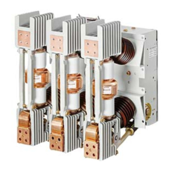
Description Description Design Vacuum circuit-breaker The 3AH3 vacuum circuit-breaker consists of • the mechanism box (60.), • the 3 pole assemblies (19.) with vacuum interrupters (30.), • the cast resin post insulators (16.1 and 16.2) with reinforcing struts (28.) and •... - Page 20 Description Pole assembly The pole assembly (19.) of the 3AH3 vacuum circuit-breaker consists of • the upper interrupter support (20.) • with the upper terminal (27.) • the vacuum interrupter (30.), • the lower interrupter support (40.) with the lower terminal (29.) and the clamp (29.2) with flexible connector (29.1);...
- Page 21 (58.) indicates the number of operating cycles. An operating cycle consists of one closing and one opening. The rating plate (51.) is attached to the mechanism box and readable through an opening (51.1) in the cover. Siemens Parts 9229 9860 176 0E 2013-08-22...
- Page 22 Description 50.2 Gear unit Position indicator CLOSED-OPEN 50.4 Motor M1 Mechanism box 50.4.1 Position switch Dashpot 50.5 Hand crank coupling Closing spring Rating plate Circuit-breaker shaft 53.1 Closing solenoid Y9 Opening spring 54.1 Shunt release Y1 Closing damper 54.2 Shunt release Y2 Auxiliary switch S1 54.3 Transformer-operated release Y4...
- Page 23 • Terminal strip (X1) Operating cycle counter Mechanical anti-pumping device Mechanical manual closing and opening Additional equipment Every 3AH3 vacuum circuit-breaker can also be fitted with the following equipment: (Y2, Y3) Shunt release 3AX1101 (Y4, Y5) Transformer-operated release 3AX1102 (Y6) Transformer-operated release 3AX1104 (0.1 AC)
- Page 24 Description Motor M1 After the supply voltage is applied and if the closing spring is discharged, the motor starts immediately and is automatically deactivated internally after charging has taken place. Power consumption, maximum: • in the event of direct voltage approx. 750 W •...
- Page 25 +10 % in the event of AC voltage. The 1st shunt release Y1 can be operated using AC or DC voltage and is protected against overvoltage. Power consumption is approximately 140 W / VA Fig. 31 1st shunt release (54.1) Siemens Parts 9229 9860 176 0E 2013-08-22...
- Page 26 Description Auxiliary switch S1 Two versions of the auxiliary switch S1 are available for delivery: with 6 or 12 NO/NC contacts each. Rated insulation voltage: 250 V AC/DC Insulation group: C as per VDE 0110 Continuous current: 10 A Closing capacity: 50 A Fig.
- Page 27 This contacting can be used for a signal. In the event of intentional mechanical opening, the cut- out switch S7 interrupts the contacting. Fig. 35 Circuit-breaker tripping signal Siemens Parts 9229 9860 176 0E 2013-08-22...
- Page 28 Description Low-voltage interface X0, 64-pole Fig. 36 Low-voltage interface X0 Fig. 37 Terminal strip (optional) For connection of the control line, the standard version of the vacuum circuit-break- ers is equipped with a 64-pole low-voltage interface X0 (68.7). The 64-pole plug (68.7.1) for the external terminal, is suitable for crimp termination of control lines with a nominal cross-section of 1.5 mm Terminal strip (optional) Instead of the 64-pole plug (68.7.1), a terminal strip (68.7.2) can be ordered as inter-...
- Page 29 Power consumption for 0.5 A and 1 A ≤ 6 VA at ≤ 90 % of the transformer-operated release's rated current and with open armature. Fig. 39 Transformer-operated releases (54.3) Siemens Parts 9229 9860 176 0E 2013-08-22...
- Page 30 Description Undervoltage release (Y7) 3AX1103 Note The undervoltage release Y7 must only be operated with the supplied series resistor R1. Note For switching operations (mechanical or electrical), the undervoltage release 3AX1103… must be connected to control voltage, as otherwise closing is not pos- sible.
- Page 31 This allows for interlocking the vacuum circuit-breaker module, for example, via the aux- iliary contact of a disconnector. Vacuum circuit-breakers with electrical manual closing cannot be switched mechanically. Siemens Parts 9229 9860 176 0E 2013-08-22...
-
Page 32: Locking Devices
Description Locking devices To lock vacuum circuit-breakers as a function of the switching position, the spring drive mechanisms of the vacuum circuit-breaker can be equipped with a locking device. This is also the case for vacuum circuit-breakers on switch gear trucks, in withdrawable sections or with disconnectors. - Page 33 A no-load switching operation is done in the course of this. Only now is it possible to undo the plug of the low-voltage interface. Note The spring charge release can also be combined with a mechanical locking device. Siemens Parts 9229 9860 176 0E 2013-08-22...
- Page 34 Description Priority opening To lock the OPEN position, the drive mechanisms of the vacuum circuit-breaker can be equipped with “priority opening”. This is also the case for vacuum circuit-breakers on switch gear trucks, in withdrawable sections or with disconnectors. Idle position Trip-free position Spring-dump position Interrogation or actuation component (min.
-
Page 35: Rating Plate
U p Quality control seal Year of manufacture Rated operating current I r Rated short-circuit duration t k Fig. 46 Example – vacuum circuit-breaker rating plate 3AH3 Mass m Rated operating sequence Classification to standard Technical data Rated voltage* U 17.5... -
Page 36: Ambient Conditions
Description Ambient conditions 3AH3 vacuum circuit-breakers are suitable for use in the following climate classes in accordance with IEC 60721, Part 3-3: Class • Climatic ambient conditions: 3Z2, • Biological ambient conditions: • Mechanical ambient conditions: • Chemically active substances: •... -
Page 37: Switching Times
Dead-time = period from the end of the current flow in all poles up to the start of cur- rent flow in the first pole. Siemens Parts 9229 9860 176 0E 2013-08-22... -
Page 38: Circuit Diagrams
Description Circuit diagrams The circuit diagrams show all the available components with their wiring options. Fig. 51 to Fig. 57 show some non-binding examples of vacuum circuit-breakers. The circuit diagrams for the vacuum circuit-breaker are compiled depending on your order. Mechanical manual closing and electrical closing “OPEN”... - Page 39 Only if a mechanical closing lock is ordered at the same time Motor winding for DC Motor winding with rectifier for AC Closing Closing with anti-pumping device Fig. 53 Sample circuit diagram 64-pole (part 1) of the vacuum circuit-breaker Siemens Parts 9229 9860 176 0E 2013-08-22...
- Page 40 Description Integrated varistor Integrated rectifier for AC/DC ≥ 100 V 1st shunt release with 64-pole plug-connector 1st shunt release with 24-pole plug-connector 2nd shunt release with 64-pole plug-connector 2nd shunt release with 24-pole plug-connector Fig. 54 Sample circuit diagram (part 2) of the vacuum circuit-breaker 9229 9860 176 0E 2013-08-22...
- Page 41 Low-energy trip-coil 1st transformer-operated release Signal: spring state with 64-pole plug-connector Signal: spring state with 24-pole plug-connector Breaker tripping signal for 64-pole plug-connector Fig. 55 Sample circuit diagram (part 3) of the vacuum circuit-breaker Siemens Parts 9229 9860 176 0E 2013-08-22...
- Page 42 Description The unassigned auxiliary switch terminals are wired up with the 64-pole plug bottom, as shown. Normal auxiliary switch Extended auxiliary switch No wiring required if 2nd shunt release Y2 available Undervoltage release Y7 available Fig. 56 Example – auxiliary switch terminals System wiring Tripping via Tripping via NO con-...
-
Page 43: Mounting
(see “Rating plate” on page 35) in order to avoid confusion. Mounting position The 3AH3 vacuum circuit-breaker can only be installed vertically (to the vacuum interrupter), as an indoor withdrawable section and as an indoor fixed installation. - Page 44 Mounting Mounting the partitions Carefully take the partitions out of the packaging (see Fig. 4) and mount according to the supplied mounting drawing. Fig. 59 Example of mounted partitions Mounting the vacuum circuit-breaker There are a total of 14 fixing holes on the pole plate (15.) and on the mechanism box (60.) for the various types of installation.
-
Page 45: Earthing
Tighten ring terminal for the earth wire with the M12 hexagon screw and washer on the earth terminal (70.) with 40 Nm. Note If the 3AH3 vacuum circuit-breaker is installed into an earthed metal frame and is connected permanently and electrically conductive, no separate earthing is required. - Page 46 Mounting Removing the transport securing device from the undervoltage release Undervoltage release (Y7) The vacuum circuit-breaker with an undervoltage release (Y7) 3AX1103 is supplied available? with a transport securing device. • Remove the two top screws (60.2) of the mechanism box. •...
-
Page 47: Electrical Connection Of The Prime Conductor
49). Note Grease the busbars with contact grease prior to mounting. The busbars can be purchased from the Siemens Service Center. Busbar connection Adjust the busbars in such a way that, before fastening, they lie flat easily and fit the holes on the contact areas of the vacuum circuit-breaker. - Page 48 Mounting Note For vacuum circuit-breakers with connecting bars, it is recommended to use the stainless steel screws or non-magnetisable screws included in the accessory pack. Fig. 68 Installing busbars flat Fig. 69 Installing busbars flat Corresponding to the rated current strength, use M12 screws and nuts – strength class 8.8 –...
-
Page 49: Operation
• Check through all of the items on the checklist and ensure correct functioning before commissioning. Commissioning Before commissioning, check the following points to ensure that the 3AH3 vacuum circuit-breaker is functioning faultlessly: Checklist Notes Does the information on the rating plate (see page 35) match the order data? Ensure correct operating voltage. -
Page 50: First Closing Operation
WARNING Do not commission the vacuum circuit-breaker if there are malfunctions. If the malfunctions or the damage cannot be remedied, contact a sales represent- ative or Siemens Service and, if necessary, send back the vacuum circuit- breaker. First closing operation If all functions have been checked and are ok, switch on high-voltage while observ- ing all of the safety regulations and operative requirements. -
Page 51: Closing
To discharge the closing spring: • the supply voltage must be deactivated • the vacuum circuit-breaker must be closed manually (see “Closing” on page 51) and then • opened manually (see “Opening” on page 51). Siemens Parts 9229 9860 176 0E 2013-08-22... - Page 52 Operation Blank page 9229 9860 176 0E 2013-08-22...
-
Page 53: Maintenance
As a cleaning agent, use only warm water with a mild, liquid household detergent added and leave to dry. Joints and bearings that cannot be disassembled must not be washed out with a detergent prior to work. Siemens Parts 9229 9860 176 0E 2013-08-22... - Page 54 Isoflex Topas L 32 Bearings and bearings of the auxiliary switch S1 Shell Tellus Oil 32 that are inaccessible in terms of greasing: Lubricants are available from the responsible Siemens representative: Order no. 180 g Isoflex Topas L 32 3AX11 33-3H...
- Page 55 Opening spring guide Spring eyelet on closing spring Deflection of auxiliary switch OPEN-latch Curve for OPEN-latch End stop Contact area of instantaneous release Fig. 73 Bearings and sliding surfaces of the operating mechanism Siemens Parts 9229 9860 176 0E 2013-08-22...
-
Page 56: Interrupter Service Life
Maintenance Interrupter service life If switching operations occur frequently under overload or short circuit, the service life of the vacuum interrupters may be reached prematurely. Replace the interrupters after reaching the maximum permitted operating cycle number of 10 000 mechanical or electrical load setting changes (up to the rated cur- rent). -
Page 57: Manufacturer's Product Liability
Republic of Germany, the applicable local laws and regulations must be complied with. Further information Contact your Siemens Service Center if you require further information. Service For details of contacts for service work, consult Siemens IC LMV SE Service at • Telephone: +49 180/5247000 • Fax: +49 180/5242471 or •... - Page 58 Maintenance Blank page 9229 9860 176 0E 2013-08-22...
-
Page 59: Index Of Keywords
Interrupter support ..........20 – Undervoltage release ......22 Interrupter, service life .......... 56 Interrupter, vacuum check ........56 Vacuum interrupter, contact system ...... 20 Locking devices ............ 32 – Low-voltage interface ........22 Siemens Parts 9229 9860 176 0E 2013-08-22... - Page 60 Index of keywords Blank page 9229 9860 176 0E 2013-08-22...
-
Page 61: Legend For All Pages
Spring state indicator 55.1 Opening for spring state indicator Operating cycle counter 58.1 Opening for operating cycle counter Position indicator CLOSED-OPEN 59.1 Opening for position indicator CLOSED- OPEN Mechanism box 60.1 Cover Dashpot Siemens Parts Closing spring 9229 9860 176 0E 2013-08-22... - Page 62 Blank page 9229 9860 176 0E 2013-08-22...
- Page 63 Blank page Siemens Parts 9229 9860 176 0E 2013-08-22...
- Page 64 Published by Siemens AG Infrastructure & Cities Sector Low and Medium Voltage Division Medium Voltage & Systems Schaltwerk Berlin Nonnendammallee 104 13629 Berlin...