
Related Manuals for Siemens SION 3AE6113-0


Summary of Contents for Siemens SION 3AE6113-0
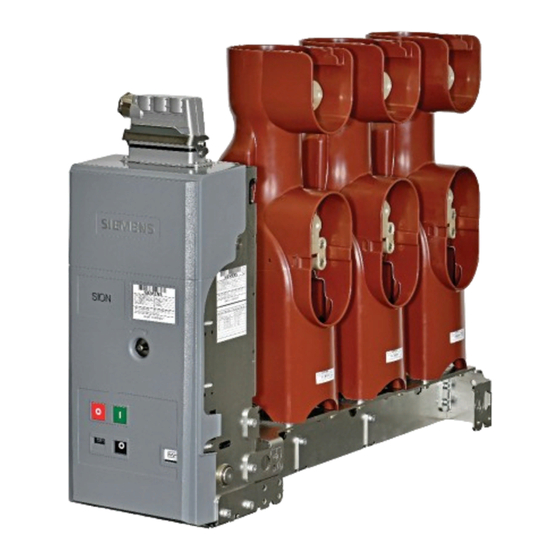
- Page 1 ® SION Lateral Vacuum circuit-breaker 12 kV – 24 kV 12.5 kA – 25 kA OPERATING INSTRUCTIONS Order No.: 9229 0020 176 0B Version: 02.2019 en © Siemens AG 2016. All rights reserved.
-
Page 2: For Your Safety
For your safety Signal terms and Hazards are classified in accordance with ISO 3864-2 using the following keywords: definitions • DANGER, WARNING, or CAUTION, where there is a risk of personal injury • NOTE, where there is a risk of material damage. Hazards are classified and indicated in the operating instructions and on the vacuum circuit-breaker as follows: DANGER... -
Page 3: Table Of Contents
Contents For your safety ..............................2 List of abbreviations ............................4 Transport, storage and packing ........................5 Transport ................................5 Unpacking ................................6 Reuse of transport unit ............................9 Storage ................................9 General information ............................11 Areas of application ............................11 Standards ................................ -
Page 4: List Of Abbreviations
List of abbreviations BGBl Bundesgesetzblatt (German Federal Law Gazette) Close-Open Deutsches Institut für Normung (German Institute for Standardisation) International Electrotechnical Commission NC contact NO contact Open Distance between pole centres RöV Röntgenverordung (German X-Ray Ordinance) Verband Deutscher Elektrotechniker (Association of German Electrical Engineers) 9229 0020 176 0B 2019-04-02... -
Page 5: Transport, Storage And Packing
Transport, storage and packing Transport, storage and packing Transport WARNING Heavy transport weight Transport unit may fall and fail and sling gear may break. Use lifting gear, transport and sling gear suited to the requirements and load-car- rying capacity. Observe transport symbols. Transport weight Refer to the delivery documents for the weight of the transport unit. -
Page 6: Unpacking
Transport, storage and packing Transporting with packing Transport the transport unit to the installation site or storage location • with a fork lift or • with sling gear suspended from a crane at a spreading angle of approx. 60° or with a spreader bar. - Page 7 Transport, storage and packing Fig. 2 Removing the fixings from the carton Opening the transport unit • Place the transport unit on a level, non-slip and pressure-resistant surface. • Remove lifting gear or transport means. • Remove plastic wrap. • Lever out fasteners from the carton and lift off carton (see Fig.
- Page 8 Transport, storage and packing Fig. 3 Example - two vacuum circuit-breakers Fig. 4 Example - one vacuum circuit-breaker Transport to the • Remove all tensioning belts and bits of fastening wood. installation site • Remove supplementary equipment and store safely in the packaging for later installation.
-
Page 9: Reuse Of Transport Unit
Attach supplementary equipment. • Close carton securely. • Before returning to the factory, ask the responsible Siemens representative for a returned goods number (see also “Service”, on page 53). • When returning a vacuum circuit-breaker, always specify the type and serial number (see “Name plate”, on page 28). - Page 10 Transport, storage and packing Blank page 9229 0020 176 0B 2019-04-02...
-
Page 11: General Information
General information General information WARNING Dangerous electrical voltage and mechanical movements When electrical devices are operated, certain parts are inevitably live under dangerous voltage, and mechanical parts may move very quickly, also when remotely controlled. If the warnings are not observed, serious injury or material damage may be the result. -
Page 12: Standards
General information Standards ® The vacuum circuit-breakers SION comply with the regulations: • IEC 62271-1 and • IEC 62271-100. ® All vacuum circuit-breakers SION comply with the specifications for C2, E2, M2 and S1-class circuit-breakers as per IEC 62271-100. Country-specific and standard-specific deviations from the standards mentioned must be observed. -
Page 13: Description
Description Description Design The images shown are examples; not all the variants of the vacuum circuit-breaker are shown here. Fig. 6 3AE6, 12 kV example Fig. 7 3AE6, 24 kV example 20.1 Cover made from insulating material Insulating operating rod 20.2 Metal cover Pole shell... - Page 14 Description Contact system in the vacuum interrupters A slight change in the contact stroke that occurs over the entire useful life has no effect on the function of the vacuum circuit-breaker. Operating mechanism The operating mechanism contains all the electrical and mechanical components re- quired to close or open the vacuum circuit-breaker.
- Page 15 Description Secondary equipment Auxiliary switch (-S1) 54.6 Position switch (-S6), circuit-breaker tripping signal (not Low-voltage plug connector (-X0), (optional) shown) Plug (Q0-X1.1, Q0-X1.2, Q0-X1.3) only when ordering the Closing spring 20-pole or 30-pole connector strip (not shown) 55.1 Spring state indicator Anti-pumping device (-K1), contactor relay (-K1) 56.3 Position indicator CLOSED-OPEN...
- Page 16 3AX11. For the permitted possible combinations of the additional equipment as well as special designs, refer to cata- logue HG11 or contact the relevant Siemens representative. 9229 0020 176 0B 2019-04-02...
- Page 17 Description Motor (-M1) After the supply voltage is applied and if the closing spring is discharged, the motor starts immediately and is automatically deactivated internally after charging has taken place. For power consumption see table Fig. 12. In the short charging time, the motor operates in the overload range.
- Page 18 Description Anti-pumping device (-K1), contactor relay (-K1) If simultaneous electrical CLOSE and OPEN commands are continuously applied to the vacuum circuit-breaker, it returns to the open position after being closed. The function of the anti-pumping device means that the vacuum circuit-breaker remains there until the ON com- mand is re-entered.
- Page 19 Description 1st shunt release (-Y1) In the case of the 1st shunt release (-Y1), the electrically fed tripping pulse is passed to the "OPEN" latch by means of a directly acting magnet armature, thus switch- ing off the vacuum circuit-breaker. The 1st shunt release (-Y1) is not designed for continu- ous operation and is terminated within the circuit-breaker via the auxiliary switch (-S1) at the factory.
- Page 20 Description Auxiliary switch (-S1) Auxiliary switch (-S1) is available for delivery in two ver- sions: With 6 NO contacts or 12 NC contacts each. Con- tacts available on the customer's premises - see circuit diagram supplied. Fig. 17 Auxiliary switch (31) Power consumption Rated insulation voltage: 250 V AC/DC...
- Page 21 Description Position switch 3AX4206-0A Position switch (-S21) switches the motor off after charg- ing the switch-on spring. Position switches (-S3) and (-S4) open when the closing spring is charged. Fig. 19 Position switch (54.2-4) Circuit-breaker tripping signal (-S6) 3AX4206-0A The position switch (-S6) makes contact briefly when the vacuum circuit-breaker is opened by means of an elec- trical release.
- Page 22 Description Low-voltage interface (-X0) Fig. 21 Low-voltage interface (-X0), 64-pole 3AX1134 Fig. 22 Low-voltage interface (-X0), retaining angle (32) with cable outlet 3AX1134 (32) For the connection of the control line, the standard version of the vacuum circuit- breakers is equipped with a 64-pole low-voltage interface (-X0). The 64-pole plug for the external terminal is suitable for crimp termination of control lines with a nominal cross-section of 1.5 mm A further shunt release, transformer-operated release or undervoltage release can...
- Page 23 Description Transformer-operated release (-Y4), (-Y5) 3AX1102, (-Y6) 3AX1104 The transformer-operated releases (-Y4), (-Y5) or (-Y6) consist of an energy storage mechanism, an unlatching fixture and an electromagnetic system. If the tripping cur- rent is exceeded (90 % of the transformer-operated re- lease's rated current), the stored energy mechanism is unlatched, thus initiating opening of the vacuum circuit- breaker.
- Page 24 Description Undervoltage release (-Y7) 3AX1103 Note The undervoltagerelease(-Y7) may only be operated with the supplied series re- sistor (-R1). Note For circuits (mechanical or electrical), the undervoltage release 3AX1103… must be connected to control voltage, as otherwise closing is not possible (refer to “Re- moving the transport block from the undervoltage release”, page 40).
-
Page 25: Locking Mechanisms
Description Heater (-R01) for condensation water protection (optional) WARNING Risk of burns! Touching the hot heater will cause burns. Do not touch the heater before it has cooled off. The heating limits condensation and corrosion of the vacuum circuit-breaker. To this end, the heating has to be connected to the sup- ply voltage (see circuit diagram included with the deliv- ery). - Page 26 Description Fig. 28 Mechanical lock Stroke in the OPEN switch position (min. 5 mm, max. 10 mm) Interrogation or actuation component (cross-section max. 14 mm x 3 mm, actuation force min. 50 N, max. 450 N) c + d Refer to dimension drawing Sectional view View from above View from below...
- Page 27 Description Key-operated interlock 3AX1437 (optional) Fig. 29 Key-operated interlock (59.3) Fig. 30 Position switch -S5 (54.5) 54.5 Position switch -S5 56.2 OPEN pushbutton 59.3 Key-operated interlock (optional) If the vacuum circuit-breaker is equipped with a key-operated interlock, it is possible to mechanically prevent both manual closing and electrical closing (position switch -S5).
-
Page 28: Name Plate
Dimensions and weights The dimensions of the vacuum circuit-breaker can be taken from the relevant dimen- sional drawing. If needed, they can be obtained from your Siemens representative. The weight is indicated on the vacuum circuit-breaker name plate (see Fig. 31) or refer to the associated dimension drawing. -
Page 29: Ambient Conditions
Description Ambient conditions Occasional condensation may occur under these ambi- ent conditions. +40 °C ® Vacuum circuit-breakers SION are suitable for use in the following climate classes according to IEC 60721, part 3-3: Class -5 °C • Climatic ambient conditions: •... -
Page 30: Switching Times
Description Switching times Closing time (closing time) ≤ 60 ms Opening time (opening time) 1st shunt release (-Y1) ≤ 30 ms 2nd release (-Y2, -Y4, -Y6, -Y7) ≤ 45 ms Arcing time < 15 ms Break time 1st shunt release (-Y1) ≤... -
Page 31: Circuit Diagrams
Description Circuit diagrams The circuit diagrams show deliverable components with their wiring options. Fig. 36 to Fig. 38 show non-binding examples of vacuum circuit-breakers. The circuit diagrams for the vacuum circuit-breaker are compiled depending on your order. Mechanical manual closing and electrical closing extended auxiliary switch “OPEN”... - Page 32 Description The unassigned auxiliary switch terminals are wired up with the 64-pole plug bottom as shown. Normal auxiliary switch Extended auxiliary switch 9862-75 No wiring required if 2nd shunt release (-Y2) available Undervoltage release (-Y7) available Fig. 37 Example - auxiliary switch terminals System wiring Tripping via Tripping via NO con-...
-
Page 33: Installation
Installation Installation DANGER High-voltage - danger to life Touching live parts causes an electric shock. • Do not touch live parts! • When work is performed on the switchgear, it must be de-energised and earthed! • The work described in the following sections must only be performed when the switchgear has been de-energised: Take safety measures to prevent reclosing! Observe industrial safety regulations! -
Page 34: Attachment In The Switching Cubicle
Installation Note For preliminary work, the vacuum circuit-breaker must be • secured against falling over, • placed onto a suitable base or • prepared for installation while suspended from a crane. Note Material damage due to incorrect operation! ® If the vacuum circuit-breaker SION is triggered manually with the cover removed and the mechanical locking device actuated, the operating mechanism of the vac- uum circuit-breaker will be irreversibly damaged. - Page 35 Installation Removing and mounting covers Remove the covers to mount the fixing lugs. Removing and mountingcover made from insulating material Fig. 40 Removing cover made from insulating materi- Fig. 41 Mounting cover made from insulating material Removing • Pull off both the engaging hooks of the cover (20.1) simultaneously. •...
- Page 36 Installation Removing and mounting metal cover 12 ±1.2 Nm Fig. 42 Removing metal cover Fig. 43 Mounting metal cover Removing • Unscrew both upper M6 hexagonal bolts. • Slightly tip metal cover (20.2), lift upwards and remove. Installation • Position lower hooks of cover above insertion slits, hook in and place cover onto operating mechanism box.
- Page 37 Installation Mounting the retaining angle for the cable outlet The version with plug or terminal strip (without low-voltage plug) is supplied with a retaining angle (60) and fixing materials in the supplementary equipment. The re- taining angle serves to bundle and protect the cables coming from the low-voltage interface.
-
Page 38: Earthing
Installation There are a different mounting holes (61) on the bearing frame for the various instal- lation types. Use strength class 8.8 screws for fastening. The binding dimension drawings and installation drawing are decisive. Earthing Note If the vacuum circuit-breaker is installed into an earthed metal frame and is con- nected permanently and electrically conductive, no separate earthing is required. - Page 39 Installation Laying the cable harness Note If the cover is made from metal, the low-voltage cable harness must only be guid- ed out of the opening in the operating mechanism box that faces away from the pole side. Fig. 49 Guiding cable harness out of operating mech- Fig.
- Page 40 Installation Wiring of connectors Q0-X1.1, Q0-X1.2, Q0-X1.3 • Remove the cover for the low-voltage interface (refer to “Removing and mounting covers” page 35). • Insert flat-head screwdriver (size 0.5 mm x 3 mm) into the plug (WAGO 231-110/026-000). • Insulation-stripped connecting lead (or with wire end ferrule) with a cross-section Single-core from 1.5 mm to 2.5 mm...
-
Page 41: Electrical Connection Of The Main Conductors
• impact depths for dowel pins or coiled spring pins, see table “Screw-in depths”, Fig. 55. The conductor bars can be purchased from the Siemens Service Center. Preparing contact surfaces Note Clean silver spray-plated and copper spray-plated contact areas with a cloth; do not brush. - Page 42 Installation Carefully brush the contact surfaces of the conductor bars cross-wise with a steel brush until they are bright and wipe off any residue using a clean cloth. After cleaning, very lightly grease the bright contact surfaces with acid-free Vaseline (e.
- Page 43 Installation Tightening torque for M12: 40 ±4 Nm M8: 24 ±4 Nm Tightening torques apply to greased threads only. Fig. 58 Assembly with spiral spring pin. Example for Fig. 59 Conductor bars (angled) installed vertically. 800 A, upper connection Example for 1 250 A Securing with a spiral The busbars can be secured against twisting with a spiral spring pin according to spring pin...
- Page 44 Installation Blank page 9229 0020 176 0B 2019-04-02...
-
Page 45: Operation
Operation Operation DANGER High voltage - danger to life! Touching live parts causes an electric shock. • Do not touch live parts! • Ensure that the vacuum circuit-breaker is operated only by qualified person- nel who are familiar with the operating instructions and who observe the warning notices. -
Page 46: Commissioning
WARNING Do not commission the vacuum circuit-breaker if there are malfunctions. If the faults or the damage cannot be remedied, contact a sales representative or Siemens Service and, if necessary, send back the vacuum circuit-breaker. 9229 0020 176 0B 2019-04-02... -
Page 47: First Closing Operation
Operation Position indicator and spring state indicator when charging the closing spring, closing and opening Input Position indicator Spring state indicator with hand crank, Charging with motor operat- ing mechanism “CLOSE” pushbut- Closing ton, Remote tripping “OPEN”... -
Page 48: Closing
Operation Hand crank If the supply voltage fails, the closing spring can be charged with a hand crank. • To do this, fit the hand crank onto the hand crank coupling through the opening with the adapter pushed forward and •... -
Page 49: Opening
Operation Opening The opening spring is charged during the closing operation. To open, send the opening command via the OPEN pushbutton or the correspond- ing command element until the vacuum circuit-breaker is open, and shows and sig- nals the OPEN switching position. Change of the switching position indicator after electrical opening: ... - Page 50 Operation Blank page 9229 0020 176 0B 2019-04-02...
-
Page 51: Maintenance
Maintenance Maintenance Maintenance and servicing DANGER High voltage - danger to life! Touching live parts is fatal or causes serious physical injury. Before beginning maintenance work, note the 5 safety rules for high-voltage equipment specified in EN 50110-1, namely: • Isolate from the power supply •... -
Page 52: Service Life Of The Vacuum Interrupters
• Parts have been incorrectly fitted or adjusted. • Adjustments are not made in accordance with Siemens specifications. • After installation and adjustment, no final test is performed with a tester approved by Siemens including documentation of the test results. -
Page 53: Disposal
If the packaging is no longer needed, it can be fully recycled. Hazardous substances When delivered by Siemens, the product does not contain any hazardous substanc- es within the scope of the Hazardous Substances Ordnance applicable to the terri- tory of the Federal Republic of Germany. For operation outside the Federal Republic of Germany, the applicable local laws and regulations must be complied with. - Page 54 Maintenance Blank page 9229 0020 176 0B 2019-04-02...
-
Page 55: Index
Index Index Accessories available for order ......52 Key-operated interlock ......14 Altitude correction factor ........29 Kinematics ............. 13 Ambient conditions ..........29 – Anti-pumping device (-K1) ....15 Locking mechanism ........13 Areas of application ..........11 Locking mechanism, mechanical ......25 Auxiliary contactor (-K1) ........ - Page 56 Index Scoring protector ........... 39 Shunt release – (-Y1), first release ......15 – (-Y2), second release ..... 15 Spiral spring pin ............ 43 Spring pin .............. 43 – Spring state indicator ........14 Standards .............. 12 Support bracket ..........13 Switching times .............
-
Page 57: Central Legend
Central legend Central legend Operating mechanism 59.4 Heater (-R01), for condensation water pro- tection (optional) 20.1 Cover made from insulating material 59.6 Resistor (-R1), for undervoltage release 20.2 Metal cover (-Y7), (optional) Name plate Bracket Auxiliary switch (-S1) Mounting holes for fixed mounting or roll Low-voltage plug connector (-X0), (optional) (optional) Plug 10-pole for (Q0-X1.1, Q0-X1.2;... - Page 58 Blank page 9229 0020 176 0B 2019-04-02...
- Page 59 Blank page 9229 0020 176 0B 2019-04-02...
- Page 60 Published by Siemens AG Energy Management Division Medium Voltages & Systems Schaltwerk Berlin Nonnendammallee 104 13629 Berlin Germany...