Table of Contents
Advertisement
SIMATIC NET
CP 243-2
AS-Interface Master
Manual
Industrial Ethernet
07/2000
C79000-G8976-C142
Release 02
AS-Interface
PROFIBUS
AS-Interface
Preface Contents
Technical Description and
Installation Instructions
Interface to the User Program
in the S7-200 CPU
Access to the Data of the AS-i
Slaves
Signaling Errors and Diagno-
stics in the User Program
Command Interface
Eliminating Problems /
Error Displays
Appendix
AS-Interface Protocol Imple-
mentation Conformance State-
ments
References
Note on the CE Mark
Support and Training
Glossary, Index
1
2
3
4
5
6
A
B
C
D
Advertisement
Table of Contents

Related Manuals for Siemens SIMATIC NET CP 243-2


Summary of Contents for Siemens SIMATIC NET CP 243-2
- Page 1 SIMATIC NET CP 243-2 AS-Interface Master Manual Industrial Ethernet PROFIBUS AS-Interface 07/2000 C79000-G8976-C142 Release 02 Preface Contents Technical Description and Installation Instructions Interface to the User Program in the S7-200 CPU Access to the Data of the AS-i Slaves Signaling Errors and Diagno-...
- Page 2 Trademarks SIMATICR, SIMATIC HMIR and SIMATIC NETR are registered trademarks of the SIEMENS AG. Third parties using for their own purpose any other names in this document which refer to trademarks might infringe upon the rights of the trademark owners.
- Page 3 This contains general information about the AS-Interface, abbreviated to AS-i in the following chapters..You want to set up an AS-i system and include the CP 243-2 module in it: – You will find the relevant information about connecting and operating the CP 243-2 in Chapter 3.
- Page 4 Preface SIMATIC NET CP 243-2 AS-i Master C79000-G8976-C142/02...
-
Page 5: Table Of Contents
............Addressing the CP 243-2 in the S7-200 CPU Meaning of the Data in the Digital Module 2.3.1... - Page 6 Dealing with Problems / Error Displays Replacing a Defective AS-Interface Slave/Automatic Address Programming . . . Error Displays of the CP 243-2 / Remedying Errors ....
- Page 7 SIMATIC NET – Support and Training Glossary Index SIMATIC NET CP 243-2 AS-i Master C79000-G8976-C142/02 .........
- Page 8 Contents SIMATIC NET CP 243-2 AS-i Master C79000-G8976-C142/02...
-
Page 9: Technical Description And Installation Instructions
Technical Description and Installation Instructions This chapter outlines the basic functions of the CP 243-2 and explains how the module is installed and started up. You will get to know the following properties of the CP 243-2: The applications The technical specifications... -
Page 10: General Notes On Operation - Safety Warnings
Caution Noise immunity/grounding To ensure the noise immunity of the CP 243-2, the CP 243-2 and the AS-i power supply unit must be correctly grounded. Caution The AS-i power supply unit used must provide a low voltage, safely isolated from the network. -
Page 11: Uses Of The Module
The accompanying product information lists the CPUs with which the CP 243-2 can be operated. From the point of view of the S7-22x CPU, the CP 243-2 represents two expansion modules (an 8DI/8DO digital module and an 8AI/8AO analog module). - Page 12 Technical Description and Installation Instructions Components Supplied The CP 243-2 product includes the following components: CP 243-2 Product information bulletin on the CP 243-2 SIMATIC NET CP 243-2 AS-i Master C79000-G8976-C142/02...
-
Page 13: Technical Specifications Of The Module
Technical Specifications of the Module The technical specifications of the CP 243-2 module are as follows: Table 1-1 Feature AS-i cycle time Configuration of the AS-Interface AS-i master profiles supported Attachment to the AS-i cable Address range Power supply SIMATIC backplane bus... -
Page 14: Installing The Module
Technical Description and Installation Instructions Installing the Module Slots in the S7-200 The CP 243-2 can be inserted in all slots for expansion modules in the S7-200 programmable controller (CPUs 22x). Possible Restrictions There may, however, be restrictions depending on the CPU or power supply unit... -
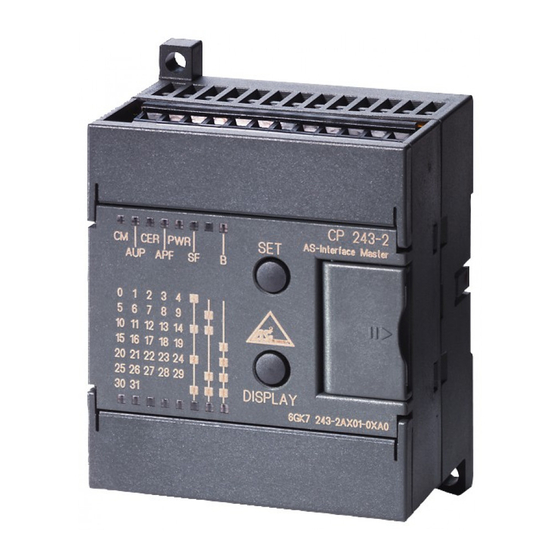
Page 15: Front Panel - Access To All Functions
Slave display AS-i cable connection Figure 1-2 Connections, Operator Controls and Interpreting the Displays For more detailed information, refer to the following sections. SIMATIC NET CP 243-2 AS-i Master C79000-G8976-C142/02 Technical Description and Installation Instructions Unused terminal block button Display... -
Page 16: Terminal Block
The load capacity of the AS-i contacts is a maximum of 3 A. If this value is exceed on the AS-i cable, the CP 243-2 must not be “looped into” the AS-i cable but must be connected by a separate cable (in this case only one pair of terminals of the CP 243-2 is used). - Page 17 Note Functional ground (terminal The CP 243-2 has a connection for functional ground. This connector should be connected to the PE conductor with as little resistance as possible. SIMATIC NET CP 243-2 AS-i Master C79000-G8976-C142/02 Technical Description and Installation Instructions...
-
Page 18: Modes Of The Cp
In this type of operation, the user program accesses the user data of the AS-i slaves and the diagnostic data of the CP 243-2. Programming is simple and this type of operation is adequate for the majority of automation tasks. -
Page 19: Displays And Operator Controls
If you do not press the DISPLAY button for a longer period of time (approximately 8 minutes). Meaning of the LEDs The front panel of the CP 243-2 has two rows of LEDs. The LEDs CM, AUP, CER, APF, PWR and SF in the upper row represent the status display. -
Page 20: Status Display
Interpreting the Status Display The status display is active when no group LEDs are lit. The status display is the default display in the basic status of the CP 243-2. Meaning of the LEDs The LEDs have the following meaning:... - Page 21 SF (red) System error This LED is lit in the following situations: The CP 243-2 has detected an internal problem (for example a defective EEPROM). The CP 243-2 is unable to make the currently required mode change (for example an AS-i slave with address 0 exists) when a button is pressed.
-
Page 22: Slave Display
If the CP 243-2 is in the configuration mode, all detected AS-i slaves are displayed. If the CP 243-2 is in the protected mode, all active AS-i slaves are displayed. In the protected mode, failed or existing but unconfigured AS-i slaves are indicated by the corresponding LED flashing. - Page 23 If the “B” LED is also lit, then in this example, this would mean that slaves 6B and 8B are active. The intersecting points mark slave 6 and slave 8. LED/column 2 + 4 Figure 1-4 Example of a Slave Display SIMATIC NET CP 243-2 AS-i Master C79000-G8976-C142/02 Technical Description and Installation Instructions group 1-15...
-
Page 24: Configuring The As-Interface With The Set Button
Pressing the SET button changes the operating mode. Note The SET button is only effective when the bit PLC_RUN = 0 is set in the control byte of the CP 243-2. This is always the case when the S7-22x CPU is in the STOP mode. Configuration Mode The configuration mode is used to install and start up an AS-i installation. - Page 25 Configuring the CP 243-2 during an AS-Interface Power Fail (for example when the AS-i power supply unit is turned off or when the CP 243-2 is not connected to the AS-Interface) resets the configuration of the CP 243-2. This has the following results: No AS-i slaves are configured;...
- Page 26 Technical Description and Installation Instructions SIMATIC NET CP 243-2 AS-i Master 1-18 C79000-G8976-C142/02...
-
Page 27: Interface To The User Program In The S7-200 Cpu
Interface to the User Program in the S7-200 CPU This chapter explains how the CP 243-2 is addressed. You will learn the significance of the data in the digital and in the analog module and you will learn how to access the analog inputs and outputs. -
Page 28: Overview
Digital Module The digital module occupies 8 input and 8 output bits in the address area of the digital inputs and outputs. The S7-200 CPU and the CP 243-2 are coordinated via the digital module. The data to be addressed in the analog module by the user program is selected using bank select bits. - Page 29 The bank select mechanism means that a larger data area in total can be addressed in the analog module than the addressable data area in the S7-200 CPU for the expansion module. SIMATIC NET CP 243-2 AS-i Master C79000-G8976-C142/02 Interface to the User Program in the S7-200 CPU...
-
Page 30: Addressing The Cp 243-2 In The S7-200 Cpu
The start addresses of the address areas are determined by the following: The type of S7-200 CPU being used The slot of the CP 243-2 in the S7-200. Examples The following table contains examples of the addresses of the digital and analog input/output areas with the possible configurations with a CPU 212 and CPU 214. - Page 31 Example of a CPU 224 and a CP 243-2 Inserted Directly Beside the CPU CPU 224 14 DI 10 DO I0.0 Q0.0 I0.1 Q0.1 I0.2 Q0.2 I0.3 Q0.3 I0.4 Q0.4 I0.5 Q0.5 I0.6 Q0.6 I0.7 Q0.7 I1.0 Q1.0 I1.1 Q1.1 I1.2...
- Page 32 Interface to the User Program in the S7-200 CPU Example of a CPU 224, an 8DI Module, a 3AI/1AO Module and a CP 243-2 CPU 224 Module 14DI 10 DO I0.0 Q0.0 I2.0 I0.1 Q0.1 I2.1 I0.2 Q0.2 I2.2 I0.3 Q0.3...
-
Page 33: Meaning Of The Data In The Digital Module
Meaning of the Data in the Digital Module Overview The digital module of the CP 243-2 consists of four registers: Identification register, 8 bits (I/O module identifier) Error register, 8 bits Input register 8DI (status byte of the CP 243-2) -
Page 34: Identification Register In The Digital Module
The identification register can be read via the special bit memory of the S7-200 CPU. It provides the fixed value 05H. Example Assuming that the CP 243-2 is inserted directly beside the S7-200 CPU. The content of the identification register can be read from SMB8. SIMATIC NET CP 243-2 AS-i Master... -
Page 35: Error Register In The Digital Module
Example of Access to the Error Register If the CP 243–2 is inserted directly beside the S7–200 CPU, SMB9 constantly supplies the value ”0”. SIMATIC NET CP 243-2 AS-i Master C79000-G8976-C142/02 Interface to the User Program in the S7-200 CPU... -
Page 36: Status Byte (Input Register 8Di)
Interface to the User Program in the S7-200 CPU 2.3.3 Status Byte (Input Register 8DI) Meaning for the User Program This register shows the status of the CP 243-2 relative to the AS-i master interface. Structure of the Status Byte Bit 7... -
Page 37: Control Byte (Output Register 8Do)
2.3.4 Control Byte (Output Register 8DO) Meaning for the User Program The user program controls the data exchange with the CP 243-2 using this register. Structure of the Control Byte Bit 7 Bit 6 Bit 5 PLC_RUN ASI_COM Description of the Bits... -
Page 38: Meaning Of The Data In The Analog Module
Interface to the User Program in the S7-200 CPU Meaning of the Data in the Analog Module Overview The analog module of the CP 243-2 consists of four areas: Identification register, 8 bits (I/O module identifier) Error register, 8 bits... -
Page 39: Identification Register In The Analog Module
The identification register can be read via the special bit memory area of the S7-200 CPU. It provides the fixed value 1FH. Example Assuming that the CP 243-2 is inserted directly beside the S7-200 CPU. The content of the identification register can be read via SMB 10. SIMATIC NET CP 243-2 AS-i Master... -
Page 40: Error Register In The Analog Module
Interface to the User Program in the S7-200 CPU 2.4.2 Error Register in the Analog Module Meaning for the User Program With this register, the CP 243-2 signals errors to the user program. Structure of the Error Register Bit 7 Bit 6... - Page 41 Example of Access to the Error Register Assuming that the CP 243-2 is inserted directly beside the S7-200 CPU. Evaluate the special memory bits SM 11.0 to SM 11.2 in the SM area (for more information about the special bit memory area of the S7-200 CPU, refer to /4/).
-
Page 42: Access To The Analog Input And Output Words
Using a bank-select mechanism, the 8 analog input words and the 8 analog output words can be switched to 64 different analog input areas (banks) and 64 different analog output areas (banks) on the CP 243-2. Each of these banks is 8 words long. - Page 43 Make sure that the value of the bank select bits is located not only in the process output image but that it is also transferred to the CP 243-2 before you access the corresponding bank (see example in Table 5-1).
-
Page 44: Analog Input Area
2.5.1 Analog Input Area Assignment of the Input Areas The input area of the analog module of the CP 243-2 is mapped to the analog inputs of the user program using bank selection as shown below: S7-200 CPU Analog inputs 8 AIW e.g. - Page 45 The delta list is updated both in the configuration and in the protected mode. The bytes and bits of the delta list are ordered as shown in the table below. (m: start address of the analog input area of the CP 243-2) Byte \ Bit...
- Page 46 Via these areas, you can access the analog input data of the AS-i slaves that support the AS-i slave profile 7.3 or 7.4 (see Section 3.1.2). Banks 48–63: Reserved area These areas are reserved for later expansions and cannot be used. 2-20 SIMATIC NET CP 243-2 AS-i Master C79000-G8976-C142/02...
-
Page 47: Analog Output Area
2.5.2 Analog Output Area Assignment of the Output Areas The output area of the analog module of the CP 243-2 is mapped to the analog outputs of the user program using bank selection as shown below: S7-200 CPU Analog outputs 8 AIW e.g. - Page 48 Interface to the User Program in the S7-200 CPU Banks 2–15: Command data on the AS-Interface Via this area, you can store command calls on the CP 243-2. The data structures and codes used are described in Section 5.2. The number of banks used depends on the particular command.
-
Page 49: Access To The Data Of The As-I Slaves
Access to the Data of the AS-i Slaves This chapter explains the AS-i master interface of the CP 243-2. The first part covers addressing the AS-i slaves and access to the binary data of the slaves. In the second part, addressing and access to the analog data of the AS-i slaves is explained. -
Page 50: Access To The Binary Data Of The As-I Slaves
(bit 1) in the digital status byte is set to ’1’. Access to the Binary Values The CP 243-2 assigns four bits (a nibble) in the input and output data area for each AS-i slave. The PLC can write (slave output data) and read (slave input data) this nibble. - Page 51 Slave 30 or slave 30A Bit 3 n = start address of the CP analog module in the output direction SIMATIC NET CP 243-2 AS-i Master C79000-G8976-C142/02 Access to the Data of the AS-i Slaves Bit 3–0 Slave 1 or slave 1A...
- Page 52 Slave 29B Slave 31B | Bit 2 | Bit 1 | Bit 0 Bit 3 | Bit 2 | Bit 1 SIMATIC NET CP 243-2 AS-i Master | Bit 0 | Bit 0 | Bit 0 | Bit 0 C79000-G8976-C142/02...
- Page 53 Data Exchange in the STOP Mode of the S7-22x CPU In the STOP mode, the S7-22x CPU sets bit PLC_RUN in the digital control area to “0” automatically. As a result, the CP 243-2 outputs “0” data to all binary slaves. Special Feature of Analog Slaves If you use analog slaves complying with profile 7.3 or 7.4 the following points...
- Page 54 Access to the Data of the AS-i Slaves Example Figure 3-1 shows an example of the CP 243-2 addressing four AS-i slaves. In the example, m = 0 is the start address for the input data and n = 0 is the start address for the output data.
-
Page 55: Access To The As-I User Data
If you want to access individual bits of the slave data, you can use the method shown in the following sample program. The example created with STEP 7 Micro/WIN32 is valid for a CPU 222 with a CP 243-2 plugged in directly beside it: OB1 (STL) NETWORK 1 SM0.1... -
Page 56: Access To The Analog Data Of The As-I Slaves (Slaves Complying With Profile 7.3 Or 7.4)
7.2. Analog value transfer for these slaves is not supported by the CP 243-2. Access to the Analog Values The CP 243-2 assigns four words in the input area and four words in the output area for each AS-i slave. The PLC can write these values (analog outputs) or read these values (analog inputs). - Page 57 Slave 8, channel 3, high byte Slave 8, channel 3, low byte Slave 8, channel 4, high byte Slave 8, channel 4, low byte Slave 9, channel 1, high byte SIMATIC NET CP 243-2 AS-i Master C79000-G8976-C142/02 Access to the Data of the AS-i Slaves...
- Page 58 Slave 14, channel 3, high byte Slave 14, channel 3, low byte Slave 14, channel 4, high byte Slave 14, channel 4, low byte Slave 15, channel 1, high byte Slave 15, channel 1, low byte 3-10 SIMATIC NET CP 243-2 AS-i Master C79000-G8976-C142/02...
- Page 59 Slave 20, channel 4, low byte Slave 21, channel 1, high byte Slave 21, channel 1, low byte Slave 21, channel 2, high byte SIMATIC NET CP 243-2 AS-i Master C79000-G8976-C142/02 Access to the Data of the AS-i Slaves 3-11...
- Page 60 Slave 26, channel 4, high byte Slave 26, channel 4, low byte Slave 27, channel 1, high byte Slave 27, channel 1, low byte Slave 27, channel 2, high byte Slave 27, channel 2, low byte 3-12 SIMATIC NET CP 243-2 AS-i Master C79000-G8976-C142/02...
- Page 61 Read access: Read analog input data from AS-i slaves Write access: Write analog output data to AS-i slaves SIMATIC NET CP 243-2 AS-i Master C79000-G8976-C142/02 Access to the Data of the AS-i Slaves 3-13...
- Page 62 In the output direction, the CP 243-2 behaves as follows: In the STOP mode of the PLC (more exactly: bit PLC_RUN = 0), the CP 243-2 stops transfer of the analog values. The reaction of the analog slave depends on the particular manufacturer.
-
Page 63: Access To The As-I Analog Data
“STEP 7 Micro/WIN32” programming language. Example The following example shown in STL is valid for a CPU 222 with a CP 243-2 plugged in directly beside it. The program reads the analog input value of slave 3 (channel 2) cyclically and sends it to the analog output slave 16 (channel 1). - Page 64 Access to the Data of the AS-i Slaves SIMATIC NET CP 243-2 AS-i Master 3-16 C79000-G8976-C142/02...
- Page 65 Signaling Errors and Diagnostics in the User Program This chapter explains which errors of the CP 243-2 are signaled and how to read out the Delta list. SIMATIC NET CP 243-2 AS-i Master C79000-G8976-C142/02...
- Page 66 Signaling Error Signaling If the CP 243-2 recognizes errors on the AS-Interface (AS-i slave failure, AS-i Power Failure) during operation, it signals these errors by resetting the input data of the affected slave and by setting the corresponding bit in the error register in the SM area (Special Memory).
- Page 67 Example: Reading the Delta List STL Example The following example in STL applies to a CPU 222 with a CP 243-2 plugged in directly beside it: If an AS-i configuration error occurs in the protected mode, the CP 243-2 sets bits SM 9.0 and SM 11.0 (both bits provide the user with the same information: AS-i...
- Page 68 Signaling Errors and Diagnostics in the User Program SIMATIC NET CP 243-2 AS-i Master C79000-G8976-C142/02...
- Page 69 You require the AS-i command interface when you want to use functions over and above pure I/O data exchange with the AS-i slaves (for example assigning parameters to slaves from within the S7-200 program, modifying slave addresses etc.). SIMATIC NET CP 243-2 AS-i Master C79000-G8976-C142/02...
- Page 70 The command buffer is in the analog output area of the CP 243-2 (for example starting at AQW0 if the CP 243-2 is plugged in directly beside an S7-200 CPU).
- Page 71 Command Sequence The diagram below shows the following: How to execute commands in the user program How the CP 243-2 reacts to a command AS-i master (user program) Set command parameter in the analog output area Initial status ASI_COM bit = 0...
- Page 72 A command started by the CP 243-2 is executed completely regardless of the state of the ASI_COM bit. The ASI_RESP bit is only reset by the CP 243-2 when the user program has set the ASI_COM bit to “0”. Example...
- Page 73 BMW AIW0, VW464, 8 Q1.0, 1 BMW AIW0, VW480, 8 Q1.0, 3 Q1.3, 1 BMW AIW0, VW496, 8 SIMATIC NET CP 243-2 AS-i Master C79000-G8976-C142/02 //Select bank 5 //V memory –> bank //Select bank 6 //Select bank 6 //V memory –> bank //Select bank 7 //V memory –>...
- Page 74 //Select bank 12 //Bank –> V memory //Select bank 13 //Bank –> V memory //Select bank 14 //Select bank 14 //Bank –> V memory //Select bank 15 //Bank –> V memory //Select bank 0 //ASI_COM SIMATIC NET CP 243-2 AS-i Master C79000-G8976-C142/02...
- Page 75 The following sections describe the AS-i command calls that can be sent by the S7-200 system to the CP 243-2. With these command calls, the CP 243-2 provides the complete functionality of the M1 master profile of the AS-i master specification.
- Page 76 Slave address Extended ID2 code Slave address I/O configuration Slave address, parameter string Slave address Parameter string Slave address ID string Slave address Diagnostic string none Error bits Input data Delta list SIMATIC NET CP 243-2 AS-i Master C79000-G8976-C142/02 Coding...
- Page 77 In the following description of the command interface, the start address 0 is assumed for the analog input module of the CP to simplify byte numbering. Table 5-4 Bank Byte SIMATIC NET CP 243-2 AS-i Master C79000-G8976-C142/02 Meaning / Content Command number Parameters for job...
- Page 78 Command status Response data Response data Response data Response data Response data Response data Response data Response data Response data Response data Response data Response data Response data Response data Response data Response data SIMATIC NET CP 243-2 AS-i Master C79000-G8976-C142/02...
- Page 79 A protocol error has occurred transferring a string according to profile 7.4. The job number or the job parameter is unknown. The AS-i master has detected an EEPROM error. SIMATIC NET CP 243-2 AS-i Master C79000-G8976-C142/02 Command Interface Meaning 5-11...
- Page 80 Standard AS-i slave or AS-i slave with extended addressing mode in address area A S bit = 1 AS-i slave with extended addressing mode in address area B 5-12 Bit 5 Bit 4 Bit 3 S bit Slave address SIMATIC NET CP 243-2 AS-i Master Bit 0 C79000-G8976-C142/02...
- Page 81 CP 243-2 . The value is saved permanently as a configured value. The configured parameter is not transferred immediately to the AS-i slave by the CP 243-2. The configured parameter value is only transferred when the AS-i slave is activated after turning on the power supply on the CP 243-2.
- Page 82 Structure of the Job Data in the Receive Buffer Bank Byte Bit 7 5-14 Meaning Command number: 01 AS-i slave address Meaning Bit 4 Bit 3 Echo of the command number: 01 Command status irrelevant Parameter SIMATIC NET CP 243-2 AS-i Master C79000-G8976-C142/02 Bit 0...
- Page 83 The AS-i parameter value transferred with the command is passed on to the addressed AS-i slave. The parameter is stored on the CP 243-2 only temporarily and is not entered as a configured parameter in the EEPROM! The AS-i slave transfers its current parameter value in the reply (parameter echo).
- Page 84 Structure of the Job Data in the Receive Buffer Bank Byte Bit 7 5-16 Meaning Command number: 03 AS-i slave address Meaning Bit 4 Bit 3 Echo of the command number: 03 Command status irrelevant Parameter SIMATIC NET CP 243-2 AS-i Master C79000-G8976-C142/02 Bit 0...
- Page 85 Structure of the Job Data in the Send Buffer Bank Byte Structure of the Job Data in the Receive Buffer Bank Byte SIMATIC NET CP 243-2 AS-i Master C79000-G8976-C142/02 Command Interface Meaning Command number: 04 Meaning Echo of the command number: 04...
- Page 86 Extended ID1 code Extended ID2 code The configuration data are stored permanently on the EEPROM of the CP 243-2 and are used as the expected configuration by the AS-i master in the protected mode. The configuration data are specified by the manufacturer of the AS-i slave.
- Page 87 Structure of the Job Data in the Send Buffer Bank Byte Bit 7 Structure of the Job Data in the Receive Buffer Bank Byte Bit 7 SIMATIC NET CP 243-2 AS-i Master C79000-G8976-C142/02 Meaning Bit 4 Bit 3 Command number 26 Slave address Meaning Bit 4 Bit 3...
- Page 88 Structure of the Job Data in the Send Buffer Bank Byte Structure of the Job Data in the Receive Buffer Bank Byte 5-20 Meaning Command number: 07 Meaning Echo of the command number: 07 Command status SIMATIC NET CP 243-2 AS-i Master C79000-G8976-C142/02...
- Page 89 Structure of the Job Data in the Send Buffer Bank Byte Bit 7 Structure of the Job Data in the Receive Buffer Bank Byte Bit 7 SIMATIC NET CP 243-2 AS-i Master C79000-G8976-C142/02 Meaning Bit 4 Bit 3 Command number 28 Slave address Meaning Bit 4 Bit 3...
- Page 90 Meaning Echo of the command number: 29 Command status SIMATIC NET CP 243-2 AS-i Master Bit 1 Bit 0 slave 6 slave 7 slave 14 slave 15 slave 22 slave 23 slave 30...
- Page 91 In the management phase, jobs from the user such as writing parameters are executed. In the offline mode, the CP 243-2 only processes jobs from the user. (Jobs that involve the immediate addressing of an AS-i slave are rejected with an error.) There is no cyclic data exchange with the AS-i slaves.
- Page 92 Structure of the Job Data in the Receive Buffer Bank Byte 5-24 Meaning Bit 1 Command number: 0B reserved Value for AUTO_ADDR_ENABLE 1=Automatic address programming enabled 0=Automatic address programming disabled Meaning Echo of the command number: 0B Command status SIMATIC NET CP 243-2 AS-i Master C79000-G8976-C142/02 Bit 0...
- Page 93 (transition to the offline phase followed by switchover to the online mode). Note If an AS-i slave with the address “0” is connected, the CP 243-2 cannot switch from the configuration mode to the protected mode. Structure of the Job Data in the Send Buffer...
- Page 94 Bank Byte Structure of the Job Data in the Receive Buffer Bank Byte 5-26 Meaning Command number: 0D Slave address old Slave address new Meaning Echo of the command number: 0D Command status SIMATIC NET CP 243-2 AS-i Master C79000-G8976-C142/02...
- Page 95 This bit is set when the AS-i slave has detected a read error when reading the non-volatile memory. Structure of the Job Data in the Send Buffer Bank Byte SIMATIC NET CP 243-2 AS-i Master C79000-G8976-C142/02 Command Interface AS-i slave complying with standard “Address/ID code volatile”...
- Page 96 Structure of the Job Data in the Receive Buffer Bank Byte Bit 7 5-28 Meaning Bit 4 Bit 3 Bit 2 Echo of the command number: 0F Command status reserved SIMATIC NET CP 243-2 AS-i Master Bit 1 Bit 0 C79000-G8976-C142/02...
- Page 97 5.2.16 Get_LPS, Get_LAS, Get_LDS, Get_Flags Purpose With this call, the following entries are read out of the AS-i master CP 243-2: The list of active AS-i slaves (LAS) The list of detected AS-i slaves (LDS) The list of permanent AS-i slaves (LPS)
- Page 98 Flag 2 Flag 2 Bit Number Meaning OFFLINE reserved EEPROM_OK AUTO_ADDR_ENABLE PERIPHERY_FAULT reserved reserved reserved SIMATIC NET CP 243-2 AS-i Master slave 14 slave 15 slave 22 slave 23 slave 30 slave 31 slave 6B slave 7B slave slave slave...
- Page 99 This flag is set when the voltage on the AS-i cable is too low. NORMAL_MODE This flag is set when the CP 243-2 is in the normal mode. CONFIG_MODE The flag is set in the configuration mode and reset in the protected mode.
- Page 100 5.2.17 Get_Extended_Total_Configuration Purpose With this command, the following data are read from the CP 243-2: The list of active slaves (LAS). This indicates which of the connected slaves are activated. The current configuration data of the connected slaves (I/O configuration and ID code).
- Page 101 ID_CODE slave 18 Ext ID1 slave 18 ID_CODE slave 19 Ext ID1 slave 19 ID_CODE slave 20 Ext ID1 slave 20 ID_CODE slave 21 Ext ID1 slave 21 SIMATIC NET CP 243-2 AS-i Master C79000-G8976-C142/02 Command Interface slave slave slave slave slave...
- Page 102 Ext ID2 slave 10B I/O configuration slave 11B Ext ID2 slave 11B I/O configuration slave 12B Ext ID2 slave 12B I/O configuration slave 13B Ext ID2 slave 13B I/O configuration slave 14B Ext ID2 slave 14B SIMATIC NET CP 243-2 AS-i Master C79000-G8976-C142/02...
- Page 103 Parameter slave 20 Parameter slave 22 Parameter slave 24 Parameter slave 26 Parameter slave 28 Parameter slave 30 SIMATIC NET CP 243-2 AS-i Master C79000-G8976-C142/02 Command Interface I/O configuration slave 15B Ext ID2 slave 15B I/O configuration slave 16B Ext ID2 slave 16B...
- Page 104 Parameter slave 13B Parameter slave 15B Parameter slave 17B Parameter slave 19B Parameter slave 21B Parameter slave 23B Parameter slave 25B Parameter slave 27B Parameter slave 29B Parameter slave 31B Flag 1 Flag 2 SIMATIC NET CP 243-2 AS-i Master C79000-G8976-C142/02...
- Page 105 The list of the AS-i slave parameters stored on the CP 243-2 (non-volatile). These are transferred to the AS-i slaves during the start up of the CP 243-2. The flags that determine the mode of the CP 243-2 after startup (in other words after the CP 243-2 has been synchronized).
- Page 106 Ext ID2 slave 20 I/O configuration slave 21 Ext ID2 slave 21 I/O configuration slave 22 Ext ID2 slave 22 I/O configuration slave 23 Ext ID2 slave 23 I/O configuration slave 24 Ext ID2 slave 24 SIMATIC NET CP 243-2 AS-i Master C79000-G8976-C142/02...
- Page 107 ID_CODE slave 15B Ext ID1 Slave 15B ID_CODE slave 16B Ext ID1 Slave 16B ID_CODE slave 17B Ext ID1 Slave 17B SIMATIC NET CP 243-2 AS-i Master C79000-G8976-C142/02 Command Interface I/O configuration slave 25 Ext ID2 slave 25 I/O configuration slave 26...
- Page 108 Parameter slave 23 Parameter slave 25 Parameter slave 27 Parameter slave 29 Parameter slave 31 Parameter slave 1B Parameter slave 3B Parameter slave 5B Parameter slave 7B Parameter slave 9B Parameter slave 11B SIMATIC NET CP 243-2 AS-i Master C79000-G8976-C142/02...
- Page 109 AS-i master with this call. Only the gray shaded flags can be modified. CONFIG_MODE The entry ‘0’ means that the CP 243-2 changes to the protected mode after executing the command. The entry ‘1’ means that the CP continues in the configuration mode.
- Page 110 Command Interface Structure of the Job Data in the Receive Buffer Bank Byte 5-42 Meaning Echo of the command number: 3A Command status SIMATIC NET CP 243-2 AS-i Master C79000-G8976-C142/02...
- Page 111 Write_Extended_Parameter_List Purpose With this command, the parameters for all slaves are transferred to the CP 243-2. The CP 243-2 transfers only the parameters that have changed, in other words that deviate from the current actual parameters to the AS-i slaves.
- Page 112 Command Interface Structure of the Job Data in the Receive Buffer Bank Byte 5-44 Meaning Echo of the command number: 3C Command status SIMATIC NET CP 243-2 AS-i Master C79000-G8976-C142/02...
- Page 113 Par echo slave 2B Par echo slave 4B Par echo slave 6B Par echo slave 8B Par echo slave 10B Par echo slave 12B SIMATIC NET CP 243-2 AS-i Master C79000-G8976-C142/02 Command Interface Meaning Bit 5 Bit 4 Bit 3...
- Page 114 Parameters slave 15B Par echo slave 17B Par echo slave 19B Par echo slave 21B Parameters slave 23B Par echo slave 25B Par echo slave 27B Par echo slave 29B Parameters slave 31B SIMATIC NET CP 243-2 AS-i Master C79000-G8976-C142/02...
- Page 115 Structure of the Job Data in the Send Buffer Bank Byte The reply of the CP 243-2 contains the name and the firmware version number of the CP 243-2 in the form shown below: Structure of the Job Data in the Receive Buffer...
- Page 116 Structure of the Job Data in the Receive Buffer Bank Byte Bit 7 5-48 Meaning Command number: 17 AS-i slave address Meaning Bit 4 Bit 3 Echo of the command number: 17 Command status reserved ID code SIMATIC NET CP 243-2 AS-i Master C79000-G8976-C142/02 Bit 0...
- Page 117 Structure of the Job Data in the Send Buffer Bank Byte Structure of the Job Data in the Receive Buffer Bank Byte Bit 7 SIMATIC NET CP 243-2 AS-i Master C79000-G8976-C142/02 Command Interface Meaning Command number: 37 AS-i slave address Meaning...
- Page 118 Byte Bit 7 5-50 Meaning Bit 4 Bit 3 Command number: 3F irrelevant Extended ID1 code Meaning Bit 4 Bit 3 Echo of the command number: 3F Command status SIMATIC NET CP 243-2 AS-i Master C79000-G8976-C142/02 Bit 0 Bit 0...
- Page 119 Structure of the Job Data in the Send Buffer Bank Byte Structure of the Job Data in the Receive Buffer Bank Byte Bit 7 SIMATIC NET CP 243-2 AS-i Master C79000-G8976-C142/02 Command Interface Meaning Command number: 38 AS-i slave address Meaning...
- Page 120 Structure of the Job Data in the Receive Buffer Bank Byte Bit 7 5-52 Meaning Command number: 18 AS-i slave address Meaning Bit 4 Bit 3 Echo of the command number: 18 Command status reserved I/O configuration SIMATIC NET CP 243-2 AS-i Master C79000-G8976-C142/02 Bit 0...
- Page 121 The bits in the LPF data have the following meaning: Bit=0: Slave signals no peripheral fault Bit=1: Slave signals peripheral faults SIMATIC NET CP 243-2 AS-i Master C79000-G8976-C142/02 Meaning Command number 3E AS-i slave address Meaning Bit 5...
- Page 122 Structure of the Job Data in the Receive Buffer Bank Byte 5-54 Meaning Slave address Number of parameter bytes String byte (1) String byte (2) String byte (n–1) String byte (n) Meaning Echo of the command number: 40 Command status SIMATIC NET CP 243-2 AS-i Master C79000-G8976-C142/02...
- Page 123 Structure of the Job Data in the Send Buffer Bank Byte Structure of the Job Data in the Receive Buffer Bank Byte Maximum value for n=220 SIMATIC NET CP 243-2 AS-i Master C79000-G8976-C142/02 Command Interface Meaning Command number 41 Slave address Meaning...
- Page 124 Maximum value for n=220 5-56 Meaning Command number 42 Slave address Meaning Echo of the command number 42 Command status Number of ID bytes String byte (1) String byte (2) String byte (n–1) String byte (n) SIMATIC NET CP 243-2 AS-i Master C79000-G8976-C142/02...
- Page 125 Structure of the Job Data in the Send Buffer Bank Byte Structure of the Job Data in the Receive Buffer Bank Byte Maximum value for n=220 SIMATIC NET CP 243-2 AS-i Master C79000-G8976-C142/02 Command Interface Meaning Command number 43 Slave address Meaning...
- Page 126 Data slave 31 Data slave 1B Data slave 3B Data slave 5B Data slave 7B Data slave 9B Data slave 11B Data slave 13B Data slave15B Data slave17B Data slave 19B SIMATIC NET CP 243-2 AS-i Master C79000-G8976-C142/02 Bit 1 Bit 0...
- Page 127 Delta Delta slave slave The meaning of the error bits APF and CER is the same as in the error register. SIMATIC NET CP 243-2 AS-i Master C79000-G8976-C142/02 Data slave 21B Data slave 13B Data slave 25B Data slave 27B...
- Page 128 Command Interface SIMATIC NET CP 243-2 AS-i Master 5-60 C79000-G8976-C142/02...
- Page 129 Dealing with Problems / Error Displays This chapter contains information about special operating states and explains how to deal with errors. SIMATIC NET CP 243-2 AS-i Master C79000-G8976-C142/02...
-
Page 130: Replacing A Defective As-Interface Slave/Automatic Address Programming
Automatic address programming by the CP 243-2 is possible. You can recognize the failed AS-Interface slave simply because the LED assigned to the slave flashes on the front panel. To do this, you must switch the CP 243-2 to the slave display (see Section 1.8.2) - Page 131 Error Displays of the CP 243-2 / Remedying Errors <F 1>The following table lists the possible causes of errors that can occur when operating the CP 243-2 and how to remedy the problem. Table 6-1 Error Displays of the CP 243-2 / Remedying Errors...
- Page 132 Dealing with Problems / Error Displays Table 6-1 Error Displays of the CP 243-2 / Remedying Errors Error The CP 243-2 does not switch The S7-200 CPU is in the “RUN” from the configuration mode to the mode. protected mode.
- Page 133 Table 6-1 Error Displays of the CP 243-2 / Remedying Errors Error Automatic address programming The configuration data (I/O confi- is unsuccessful although the guration, ID codes) of the repla- “AUP” display is lit. ced AS-Interface slave do not match the values of the original AS-Interface slave.
- Page 134 Dealing with Problems / Error Displays SIMATIC NET CP 243-2 AS-i Master C79000-G8976-C142/02...
- Page 135 SIMATIC NET CP 243-2 AS-i Master C79000-G8976-C142/02 Comment / Function implemented by / Section By access to the I/O data of the CP 243-2 module by the DP master. By access to the I/O data of the CP 243-2 module by the DP master.
- Page 136 Get_LPS, Get_LAS, Get_LDS, Get_Flags see Section 5.2.16 Get_LPS, Get_LAS, Get_LDS, Get_Flags see Section 5.2.16 By pressing the SET button; or with the command Set_operation_mode see Section 5.2.13 see Section 5.2.11 – not implemented SIMATIC NET CP 243-2 AS-i Master C79000-G8976-C142/02...
- Page 137 STATRES) Symbols in column 3 (M2) Symbol Meaning Function exists – Function does not exist SIMATIC NET CP 243-2 AS-i Master C79000-G8976-C142/02 AS-Interface Protocol Implementation Comment / Function implemented by / Section see Section 5.2.14 see Section5.2.12 Get_LPS, Get_LAS, Get_LDS, Get_Flags / see Section 5.2.16...
- Page 138 AS-Interface cycle; in other words, the calculated cycle time is doubled for these slaves. The calculated cycle time applies assuming that no frames are repeated, there are no management calls and all slaves are synchronized. SIMATIC NET CP 243-2 AS-i Master C79000-G8976-C142/02...
- Page 139 (The AS-i technology is promoted by the AS-Interface Association e. V.) Internet address of the AS-International Association e.V.: SIMATIC NET Industrial Communications Networks Catalog IK 10 The catalog can be ordered from your local SIEMENS branch office or distributor. SIMATIC S7-200 Programmable Controller / System Manual Siemens AG...
- Page 140 References Profibus & AS-Interface Components on the Field Bus Catalog ST PI The catalog can be ordered from your local SIEMENS branch office or distributor. SIMATIC STEP 7-Micro/DOS Manual Siemens AG Order numbers The order numbers of the SIEMENS documentation listed above can be found in the catalogs “SIMATIC NET Industrial Communication, Catalog IK10”...
- Page 141 EU directive for machines 89/392/EEC. If the product is integrated as part of a machine, it must be included in the conformity application of the manufacturer. SIMATIC NET CP 243-2 AS-i Master C79000-G8976-C142/02 Requirements Noise emission...
- Page 142 Notes on the CE Mark SIMATIC NET CP 243-2 AS-i Master C79000-G8976-C142/02...
- Page 143 SIMATIC BASIC Hotline Local time:Mo.-Fr. 8:00 to 18:00 Phone: +49 (911) 895-7000 Fax: +49 (911) 895-7002 E-mail: simatic.support@ nbgm.siemens.de SIMATIC NET CP 243-2 AS-i Master C79000-G8976-C142/02 Nuremberg Singapore SIMATIC Basic Hotline Johnson City Singapore SIMATIC BASIC Hotline SIMATIC BASIC Hotline Local time:Mo.-Fr.
- Page 144 8, N, 1, ANSI, or dial in using ISDN (x.75, 64 Kbps). Further Support If you have further questions on SIMATIC NET products, please contact your Siemens representative in your local Siemens office. The addresses are listed: S in our catalog IK 10 S on the Internet (http://www.ad.siemens.de)
- Page 145 The AS-i master is used to monitor and control the simplest binary actuators and sensors via AS-i modules or AS-i slaves. A distinction is made between a standard AS-i master and an extended AS-i master. SIMATIC NET CP 243-2 AS-i Master C79000-G8976-C142/02 Glossary-1...
- Page 146 The extended AS-i masters of SIMATIC NET support the integrated transfer of AS-Interface analog slaves that operate in compliance with Profile 7.3/7.4 of the AS-Interface Specification. List of activated slaves. List of detected slaves. List of permanent slaves. Glossary-2 SIMATIC NET CP 243-2 AS-i Master C79000-G8976-C142/02...
- Page 147 A nibble is a unit of information consisting of four bits. Standard AS-i master Up to 31 standard slaves or slaves with the extended addressing mode (A slaves only) can be attached to a standard AS-i master. SIMATIC NET CP 243-2 AS-i Master C79000-G8976-C142/02 Glossary Glossary-3...
- Page 148 Glossary SIMATIC NET CP 243-2 AS-i Master Glossary-4 C79000-G8976-C142/02...
- Page 149 Index Addressing AS-i slaves, 3-2 example, 3-6 examples, 2-4 the CP 243-2 in the S7-200 CPU, 2-4 Analog input and output words, access to, 2-16 Analog input area, 2-18 Analog module, 2-2, 2-13 Analog output area, 2-21 AS–Interface, cycle time, A-4 AS-i.
- Page 150 Status byte, 2-11 Status display, 1-12 STEP 7 Micro, 3-7, 3-15 Technical specifications, 1-5 Terminal block, 1-8 Terminal contacts, 1-8, 1-10 Transmission rate, PROFIBUS, 1-5 User data, 3-7, 3-15 User program, interface to, 2-1 SIMATIC NET CP 243-2 AS-i Master C79000-G8976-C142/02...