Table of Contents
Advertisement
Quick Links
INSTALLATION/USER MANUAL
• Make sure to read the cautions for safety before installation and use, and use
it correctly.
• It is intended to keep protect the safety of the installer and user and to
prevent the property damage, etc.
• After reading the user manual, please keep it at a place where user can
access any time.
TYPE : ACS IO MODULE
MODEL : PEXPMB000
P/NO : MFL67657108
www.lg.com
Advertisement
Table of Contents

Related Manuals for LG V-NET ACS IO


Summary of Contents for LG V-NET ACS IO
- Page 1 • It is intended to keep protect the safety of the installer and user and to prevent the property damage, etc. • After reading the user manual, please keep it at a place where user can access any time. TYPE : ACS IO MODULE MODEL : PEXPMB000 www.lg.com P/NO : MFL67657108...
- Page 2 TIPS FOR SAVING ENERGY TIPS FOR SAVING ENERGY Here are some tips that will help you minimize the power consumption when you use the air conditioner. You can use your air conditioner more efficiently by referring to the instructions below: •...
-
Page 3: Important Safety Instructions
IMPORTANT SAFETY INSTRUCTIONS IMPORTANT SAFETY INSTRUCTIONS READ ALL INSTRUCTIONS BEFORE USING THE APPLIANCE. Always comply with the following precautions to avoid dangerous situations and ensure peak performance of your product WARNING It can result in serious injury or death when the directions are ignored CAUTION It can result in minor injury or product damage when the directions are ignored WARNING... - Page 4 SAFETY PRECAUTIONS - Failure to do so can cause fire and electric shock. • Do not use a power cord that has been damaged, sabotaged or overly bent. - Failure to do so can cause fire and electric shock. • Do no connect the power cord to the control signal line socket. - Doing so can cause fire and electric shock.
-
Page 5: Table Of Contents
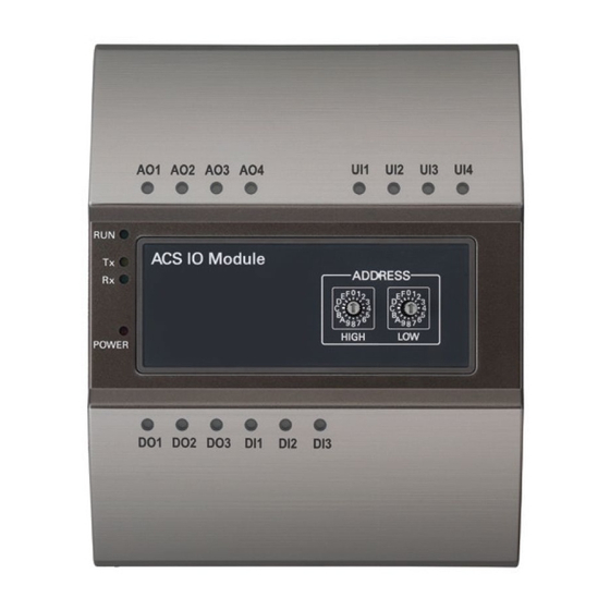
TABLE OF CONTENTS TABLE OF CONTENTS TIPS FOR SAVING ENERGY USING THE PRODUCT LED status IMPORTANT SAFETY Connecting to an external device (DI port) INSTRUCTIONS LED status (DI port) PRODUCT FUNCTIONS Connecting to an external device (DO port) AND SPECIFICATIONS LED status (DO port) The names of each part Connecting to an external device (UI port) -
Page 6: Product Functions And Specifications
PRODUCT FUNCTIONS AND SPECIFICATIONS PRODUCT FUNCTIONS AND SPECIFICATIONS The ACS IO is a module that can be connected with the ACS IV Controller (AC Smart IV, and ACP IV) for scalability in case the ACS IV Controller does not have enough DI, DO ports, or in case one wants to use an AI, AO port. -
Page 7: Components
PRODUCT FUNCTIONS AND SPECIFICATIONS Components There are following components in the ACS IO package box. Open the package box of ACS IO and check whether all the components are enclosed. ACS IO Module ACS IO User guidelines Installation screws Hardware and exterior specifications The ACS IO hardware specification are as follows. -
Page 8: Product Installation
PRODUCT INSTALLATION PRODUCT INSTALLATION ACS IO installation methods There are two methods as seen below for attaching the ACS IO to the wall. Attaching the ACS IO the wall The ACS IO can be installed by attaching it to the wall. •... -
Page 9: Mounting The Acs Io To A Din Rail
PRODUCT INSTALLATION Mounting the ACS IO to a DIN Rail The ACS IO can be installed on a DIN Rail with a width of 35 mm and a height of 7.5 mm. Follow the instructions below to install the ACS IO in a suitable location. •... -
Page 10: Connecting The Product
PRODUCT INSTALLATION Connecting the product The illustration below shows all the cable connections of the ACS IO. Universal Voltage/current/resistance/ Analog voltage output digital input (dry only) ACS IO Module Power supply Relay Digital Input Transformer On/Off output (Dry Only) 24 V~ BUS A BUS B ACS IV... -
Page 11: Inputting Power Source
PRODUCT INSTALLATION Inputting power source Use a power source of 24 V~ conforming to local and national codes. ACS IO Module L : Live N : Neutral Transformer 24 V~ CAUTION • When connecting the power source confirm the location of the power source connector and connect it firmly. - Page 12 PRODUCT INSTALLATION Connecting the communication Link Connecting the RS485 communication link The two RS485 cables must be connected to the BUS_A of the ACS IO and the BUS_B to con- nect the ACS IO with the ACS IV Controller Refer to the following illustration when connecting the RS485 cable. ACS IO Module BUS A BUS B...
- Page 13 PRODUCT INSTALLATION Connecting the ACS IV Controller to the ACS IO A maximum of 16 ACS IO’s can be connected to a single ACS IV Controller. When there are multiple ACS IO, RS485 communication cable must be installed using the daisy chain method.
-
Page 14: Address Creation
PRODUCT INSTALLATION Address creation ACS IO Address Creation When one ACS IV Controller(AC Smart IV, ACP IV) is connected to multiple ACS IO, to classify each module a unique address must be used by selecting rotary switches. ACS IO Module Using the ACS IO rotary switch a 16 digit between 01~F7 can be created. - Page 15 PRODUCT INSTALLATION Recommended address • Recommended address range : 20~2F • Valid address range : 01~F7 ACS IO Module Address : 0x20 AC Smart IV ACS IO Module Address : 0x21 ACP IV Address : 0x22 ACS IO Module ACS IV Controller Address : 0x2F ACS IO Module CAUTION...
-
Page 16: Using The Product
USING THE PRODUCT USING THE PRODUCT This chapter will describe about the methods of use for the ACS IO. LED status ACS IO Module RUN LED : This is used to confirm that normal operations have been established after con- necting to ACS IO. -
Page 17: Connecting To An External Device (Di Port)
USING THE PRODUCT Connecting to an external device (DI port) The dry contact input method is provided for DI ports. Do not apply external power to DI ports. Damage will occur and warranty will be voided. There are a total of 3 DI ports. ACS IO Module + : Input - : GND... -
Page 18: Connecting To An External Device (Do Port)
USING THE PRODUCT Connecting to an external device (DO port) As for the DO port, this is a contact output port. There are a total of 3 DO ports. ACS IO Module CAUTION • The maximum output possible for switching through digital output is DC 30 V/30 V~ and the maximum current is 2 A. -
Page 19: Connecting To An External Device (Ui Port)
USING THE PRODUCT Connecting to an external device (UI port) Each of four UI ports can be configured for use as analog in or digital in only. There are a total of 4 UI ports. + : Input ACS IO Module - : GND The table below shows the valid configuration values for each of four UI ports. -
Page 20: Led Status (Ui Port)
USING THE PRODUCT LED status (UI port) The input status LED will light up under the following circumstances. Types of LED input Minimum value NTC 10k PT 1000 Analog Input Ni 1000 DC(Voltage) DC(Current) Digital Input Binary(Dry contact) When there is an input value, ON... -
Page 21: Connecting To An External Device (Ao Port)
USING THE PRODUCT Connecting to an external device (AO Port) Each of four analog output ports will provide between 0 and DC 10 V depending on central controller configuration. + : Output ACS IO Module - : GND CAUTION • Connecting the wrong size cable results in damage and a malfunction of the product. •... - Page 22 Class A device NOTE This equipment has been tested and found to comply with the limits for a Class A digital device, pursuant to part 15 of the FCC Rules. These limits are designed to pro-vide reasonable protection against harmful interference when the equipment is operated in a commercial environment.
- Page 23 Ver. 1.0.0...