Table of Contents
Advertisement
Installation and Maintenance Manual
R-410A 50Hz T1 Heat Pump
Model:YAKN09BZNWEUH1
YAKN12BZNWEUH1
YEKN18BZNWEUH1
YEKN24BZNWEUH1
YEKN36BZNWEUH1
YEKN42BZMWEUH1
YGKN48BZMWEUH1
YGKN55BZMWEUH1
Version:YPM2017009HC
Ducted Air Conditioner
R-410A 50Hz T1 Cooling Only
Model:YAJN09BZNWETH1
YAJN12BZNWETH1
YEJN18BZNWETH1
YEJN24BZNWETH1
YEJN36BZNWETH1
YEJN42BZMWETH1
YGJN48BZMWETH1
YGJN55BZMWETH1
Advertisement
Table of Contents

Related Manuals for York YAKN09BZNWEUH1


Summary of Contents for York YAKN09BZNWEUH1
- Page 1 Installation and Maintenance Manual Ducted Air Conditioner R-410A 50Hz T1 Heat Pump R-410A 50Hz T1 Cooling Only Model:YAKN09BZNWEUH1 Model:YAJN09BZNWETH1 YAKN12BZNWEUH1 YAJN12BZNWETH1 YEKN18BZNWEUH1 YEJN18BZNWETH1 YEKN24BZNWEUH1 YEJN24BZNWETH1 YEKN36BZNWEUH1 YEJN36BZNWETH1 YEKN42BZMWEUH1 YEJN42BZMWETH1 YGKN48BZMWEUH1 YGJN48BZMWETH1 YGKN55BZMWEUH1 YGJN55BZMWETH1 Version:YPM2017009HC...
-
Page 2: Table Of Contents
Contents Caution Statements...............................1 Composition of the Air-Conditioner........................2 Operation manual Special Remarks..............................3 Troubleshooting..............................3 Diagram of Refrigerant Cycle & Wiring 1.Refrigerant Flow Diagram..........................4 2.Electrical Wiring Diagram..........................4 Installation and Maintenance 1.Safety Notice ..............................5 2.The Tools and Instruments for Installation......................6 3.The Installation of the Indoor Unit ........................6 3.1 The Initial Check ............................6 3.2 Installation..............................7 4. -
Page 3: Caution Statements
CAUTION Statements We recommend that this air-conditioner is installed properly by qualified installation technicians in accordance with the installation instructions provided with the unit. Before installation, check if the voltage of the power supply at installation site is the same as the voltage shown on the nameplate. -
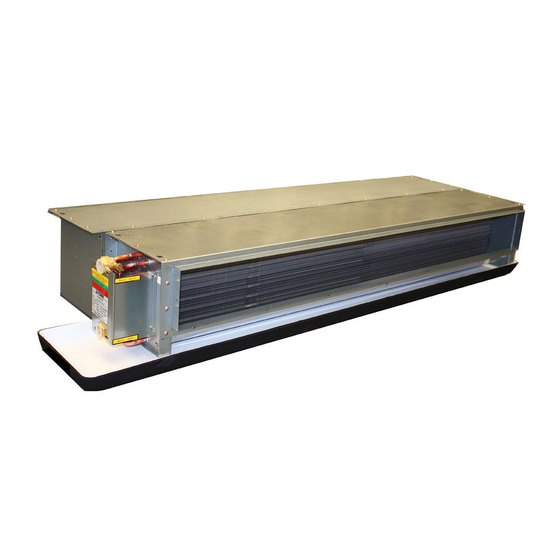
Page 4: Composition Of The Air-Conditioner
Composition of the Air-conditioner Indoor unit Air inlet Electric box Air outlet The conditioned air is blown out of the air-conditioner through it. Outdoor unit 9K,12K,18K,24K,36K,42K 48K,55K Remote controller (Optional) You can control the air-conditioner with the wired remote controller or wireless remote controller. It is used for power ON/OFF, setting the operation mode, temperature, fan speed and other functions. -
Page 5: Operation Manual
Operation manual Special remarks ● 3 minutes protection after compressor stop To protect compressor, it will be continue off for at lest 3 minutes once it has stopped. ● 5 minutes protection Compressor must run 5 minutes at least once start running. In the 5 minutes, compressor will not stop even the room temperature reaches the setting temperature point unless you use remote remote controller turn off the unit (all indoor unit can be turned off by user). -
Page 6: Diagram Of Refrigerant Cycle & Wiring
Diagram of refrigerant cycle & Wiring 1.Refrigerant Flow Diagram INDOOR UNIT OUTDOOR UNIT Gas piping Compressor Accumulator Wide service valve 4-way valve Liquid piping Service valve Heating cycle Cooling cycle 2.Electrical W iring Diagram Outdoor unit Indoor unit Indoor unit Outdoor unit Terminal Terminal... -
Page 7: Installation And Maintenance
Installation and Maintenance 1.Safety Notice WARNING ·Installation should be performed by a professional. (Improper installation may cause water leakage, electrical shock or fire.) ·Install the unit according to the instruction given in this manual. (Incomplete installation may cause water leakage, electrical shock or fire). ·Be sure to use the supplied or specified installation parts. -
Page 8: The Tools And Instruments For Installation
Installation and Maintenance 2.The Tools and Instruments for Installation Number Tool Number Tool Standard screwdriver Knife or wire stripper Vacuum pump Gradienter Charge hose Hammer Pipe bender Churn drill Adjustable wrench Tube expander Inner hexagon spanner Pipe cutter Cross head screw-driver Tape measure 3.The Installation of the Indoor Unit CAUTION... -
Page 9: Installation
Installation and Maintenance · Optimum air distribution is ensured. 3.2 Installation · The air path is not blocked. · Condensation can drain properly. 3.2.1 Suspension bolts · The ceiling is strong enough to bear the weight of the (1) Consider the pipe direction, wiring and maintenance indoor unit. - Page 10 Installation and Maintenance Air outlet Hanger bracket Suspension bolt Rack Indoor unit Double nuts and washers Fig. 3.6 3.2.4 The horizontal adjustment of the indoor unit (1) Make sure that the hanger bracket is fixed by the nuts and the washers. Air inlet (2) Adjust the height of the unit.
-
Page 11: Refrigerant Piping
Installation and Maintenance 4.Refrigerant Pipe (2) As shown in Fig. 4.3, screw up the nuts with 2 spanners. DANGER Use the refrigerant according to outdoor nameplate. When carrying on the leakage check and test, do not mix in the oxygen, the acetylene and flammable and the reactive gas, these gases are quite dangerous, and may possibly cause explosion. -
Page 12: Drain Piping
Installation and Maintenance 5.Drain piping · Drain piping passing indoors · Install the drain piping · Drain sockets. · Referring the figure below, insulate the drain socket Refrigerant pipes and drain hose using the included large sealing pad. Sealing material Sealing material Drain pipe connection hole (external straight pipe thread) -
Page 13: Electrical Wiring
Installation and Maintenance 6.Electrical Wiring General Check CAUTION · When clamping the wiring, use the included clamping material as shown in the FIG.6.1 to prevent outside pressure being exerted on the wiring connections and clamp firmly. · When doing the wiring, make sure the wiring is neat and does not cause the control box lid to stick up, then close the cover firmly. -
Page 14: Hange Of Static Pressure
Installation and Maintenance Installation and Maintenance 6.2 Change of Static Pressure The static pressure outside the indoor unit can be chosen. 6.2.1 For AC MOTOR type: You can change the static pressure by changing the fan motor terminal which refer to following Fig6.2.1. Fan motor Low static pressure Low static... -
Page 15: The Installation Of The Outdoor Unit
Installation and Maintenance 7.The Installation of the Outdoor Unit Tube length L Indoor unit 7.1 Installation Sites Avoid Height difference H Outdoor unit Direct sunlight Aisle Or sideway Thick Oil fog Wet Or Uneven place Container With Flammable materials Add. Near Heat Source/ventilation fan Max. -
Page 16: Refrigerant Piping
Installation and Maintenance 8. Refrigerant Piping The two refrigerant tubes (and electrical wire if local 8.1 Flaring with Tube Expander codes permit) should be taped together with white Note: A good flare have the following characteristics: armoring tape. The drain hose may also e included Inside surface is glossy and smooth. -
Page 17: Air Purging And Test Run
Installation and Maintenance 9.Air purging and test run WARNING · Only after all the checking points have been checked Air and moisture remaining in the refrigerant system the unit can be operated. have undesirable effects. (A) Check and make sure that the resistance of the Therefore, they must be purged completely following the Ω... -
Page 18: Electrical Installation
Installation and Maintenance 9.5 Electrical Installation ● Use an ELB (Electric Leakage Breaker). If not used, it MAY cause an electric shock or a fire. ● Do not operate the system until all the check points have been cleared. (A) Check to ensure that the insulation resistance is more than 2 MΩ, by measuring the resistance between ground and the terminal of the electrical parts. - Page 19 Correct Disposal of this product This marking indicates that this product should not be disposed with other household wastes throughout the EU. To prevent possible harm to the environment or human health from uncontrolled waste disposal, recycle it responsibly to promote the sustainable reuse of material resources.