
Related Manuals for York YKHC 18


Summary of Contents for York YKHC 18
-
Page 1: Service Manual
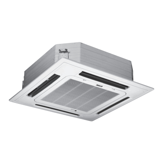
Cassette YKHC 18 to 48 SERVICE MANUAL YKHC 18 · YKHC 24 · YKHC 30 · YKHC 36 · YKHC 48 SM-YKHC-18-48GB 03-07... - Page 2 A = First H = High wall R = New remote M = Master range P = Portable Y = YORK Voltages: R = Everest front A = (Out) 220-240/1/50 - (In) 220-240/1/50 C = (Out) 380/3/50 - (In) 220-240/1/50...
- Page 3 Four-way Cassette Type Part1. Product features 1) Low operation noise ---Streamline plate ensures quietness ---Creates natural and comfortable environment 2) Fresh air make life more healthy and comfortable. 3) Efficient cooling ---Equal, fast and wide—range cooling Four-way airflow 4) The adoption of the most advanced 3- Dimensional Screw fan ---Reduces the air resistance passing through ---Smoothes the air flow ---Makes air speed distribution to the heat exchange uniform...
-
Page 4: Indoor Fan
Part2. Speci cation YKHC-18 YKHC-24 Model 1,220-240V,50Hz 1,220-240V,50Hz 18000 24000 Capacity Btu/h Capacity 1900 2560 Cooling 12.2 20500 27300 Capacity 1900 2500 Heating 10.7 10.9 2300 3300 11.7 15.3 PA290X3CS-4MU1 C-SBN303H8D Model ROTARY SCROLL Type TOSHIBA SANYO Brand TOSHIBA SANYO(Dalian) Supplier (Guangdong) 18362... -
Page 5: Outdoor Fan
Dimension (W*H*D)(body) 580 254 580 840 240 840 Packing (W*H*D)(body) 750 340 750 1020 330 930 Net/Gross weight(body) 21/30 36/46 Indoor unit Dimension (W*H*D)(panel) 650 30 650 950 40 950 Packing (W*H*D)(panel) 715 115 715 1030 145 1030 Net/Gross weight(panel) 6/11 Model YDK53-6K... - Page 6 Model YKHC-30 YKHC-36 YKHC-48 Power supply Ph-V-Hz 3,380V,50Hz 3,380V,50Hz 3,380V,50Hz Capacity Btu/h 30000 36000 48000 Capacity 10.5 Cooling Input 3250 3700 4700 Rated current Btu/W.h Capacity Btu/h 32000 39000 52000 Capacity 11.4 15.2 Heating Input 3250 3350 4900 Rated current Btu/W.h 10.9 11.5...
- Page 7 Dimension (W*H*D)(body) 840 310 840 840 310 840 840 310 840 Packing (W*H*D)(body) 1020 400 930 1020 400 930 1020 400 930 Net/Gross weight(body) 40/50 40/50 40/50 Indoor unit Dimension (W*H*D)(panel) 950 40 950 950 40 950 950 40 950 Packing (W*H*D)(panel) 1030 145 1030...
- Page 8 anechoic room. Part 3. Noise level FOUR-WAY CASSETTE TYPE 1.0m Microphone 12.000~24,000 btu/h 30,000~48,000 btu/h Audibility limits of Audibility limits of continuous white continuous white sound sound Octave band center frequency £¨ Hz £© Octave band center frequency £¨ Hz £©...
- Page 9 Part4. Velocity & temperature distribution Discharge angle 60º Airflow velocity Temperature Part5. Operation range Ensure the operating temperature is in allowable range. Heating Cooling Indoor temp.(¡ã C) Indoor temp.(¡ã C)
- Page 10 Part6. Capacity table Model: YKHC 12-18 COOLING OUTDOOR CONDITIONS Indoor 21ºC 25ºC 30ºC 35ºC 40ºC 45ºC 50ºC Conditions Total capacity kW 5.12 4.90 4.72 4.45 4.27 4.14 4.01 21ºC D Sensitive capacity kW 4.10 3.92 3.78 3.56 3.42 3.31 3.21 15ºC W Input kW.
- Page 11 Model: YKHC-24 COOLING OUTDOOR CONDITIONS Indoor 21ºC 25ºC 30ºC 35ºC 40ºC 45ºC 50ºC Conditions Total capacity kW 6.86 6.56 6.32 5.96 5.73 5.55 5.37 21ºC D Sensitive capacity kW 5.49 5.25 5.06 4.77 4.58 4.44 4.29 15ºC W Input kW. 1.61 1.84 2.07...
- Page 12 Model: YKHC-30 COOLING OUTDOOR CONDITIONS Indoor 21ºC 25ºC 30ºC 35ºC 40ºC 45ºC 50ºC Conditions Total capacity kW 8.50 8.13 7.84 7.39 7.10 6.87 6.65 21ºC D Sensitive capacity kW 6.80 6.50 6.27 5.91 5.68 5.50 5.32 15ºC W Input kW. 2.05 2.34 2.63...
- Page 13 Model: YKHC-36 COOLING OUTDOOR CONDITIONS Indoor 21ºC 25ºC 30ºC 35ºC 40ºC 45ºC 50ºC Conditions Total capacity kW 10.14 9.70 9.35 8.82 8.47 8.20 7.94 21ºC D Sensitive capacity kW 8.11 7.76 7.48 7.06 6.77 6.56 6.35 15ºC W Input kW. 2.33 2.66 3.00...
- Page 14 Model: YKHC-48 COOLING OUTDOOR CONDITIONS Indoor 21ºC 25ºC 30ºC 35ºC 40ºC 45ºC 50ºC Conditions Total capacity kW 13.52 12.94 12.47 11.76 11.29 10.94 10.58 21ºC D Sensitive capacity kW 10.82 10.35 9.97 9.41 9.03 8.75 8.47 15ºC W Input kW. 2.96 3.38 3.81...
-
Page 15: Table Of Contents
Part7. Electric control functions 1. Performance Index Item Index Applicable Voltage Range 165-253V~, 343-418V~ A/C Frequency 50Hz Working environment temperature -7°C- +45°C 2. Main Parts Introduction 2.1 Indoor Fan High speed and low speed. Breeze speed for anti-cold air. 2.2 Outdoor Fan High speed and low speed. -
Page 16: Buzzer
3. Operation Modes and Functions 3.1 Manual Operation 3.1.1 The manual operation mode is controlled through “manual” pad in the wind in-take grid, including such two modes as manual action and manual cooling. Push the manual pad for each switchover, the order for which is shown below: REMOTE CONTROL MANUAL ACTION... -
Page 17: Four-Way Valve
3.2 Heating Mode 3.2.1 Four-way valve opens at once, while defrosting process closes. 3.2.2 Condition for the compressor action: (Ts = set temperature, Ta = room temperature) Condition Compressor Outdoor fan Room temp. up Ta> Ts+4 Ta<Ts+4 Room temp. down Ta<... - Page 18 3.3 Defrost (only available to heating mode) 3.3.1 The defrosting of 2HP, 3HP is processed by indoor control board. 3.3.1.1 Defrosting Conditions 3.3.1.1.1 Low temperature defrosting condition: Accumulated operating time when temperature of outdoor heat exchanger coil T3 is below -2°C reaches up to over 40 minutes.
-
Page 19: Cooling Mode
3.4 Cooling Mode 3.4.1 Four-way valve is closed. If four-way valve is open before the mechine enters cooling mode, then four-way valve will be closed at the first time the compressor starts under the cooling mode. 3.4.2 Conditions for the compressor and outdoor fan action (Ts = set temperature, Ta=room temperature) Condition Compressor Outdoor fan... -
Page 20: Condensate Pump
4. Other Functions 4.1 LED Display Operation lamp, timer lamp, defrosting/pre-heating lamp, and water level alarm lamp. 4.1.1 Operation Lamp When the operation is recovering, it will blink at 1 Hz. After the unit is on, the lamp will keep on. After the unit is off, the lamp will be off. -
Page 21: Trouble Shooting
5. Trouble Shooting 5.1 Protective Function 5.1.1 3-minute delay for the compressor start-up. At the beginning of energizing or after the stop of the compressor, 3-minute delay will be needed to start the compressor. When switchover between cooling/heating mode, the compressor stops automatically. 5.1.2 Compressor current overload protection 5.1.2.1 3HP compressor current examination and action... - Page 22 5.1.3 Evaporator protection against high temperature(heating mode) Only available to heating mode, including heating mode, heating operation under auto mode. Note: During protection, the indoor fan continues operating at a setting speed, while the anti-cold air function of heating and the compressor will be 3 minute delayed to shut down for protection. 5.1.4 Evaporator Protection against low temperature(cooling mode) 5.1.4.1 When the evaporator pipe temperature 3°c and this lasts for 3 minutes, the compressor and outdoor...
- Page 23 5.2 Self-diagnosis 5.2.1 Indoor unit Type Contents LED Flashing Remark protection Over current protection Lamps of operation, timer, Whole unit is shut down. compressor occurs 4 times in 1h defrosting (only fan ) flashing It cannot recover unless simultaneously at 5Hz. power is cut off protection Outdoor protection (absent phrase,...
- Page 24 Part8. Wiring diagram 1. YKHC-12-18 Indoor unit: Outdoor unit:...
-
Page 25: Indoor Unit
2. YKHC-24 Indoor unit: Outdoor unit: CAP1 CAP2 COMP XS1,XP1 VALVE... - Page 26 3. YKHC-30 YKHC-36 Indoor unit: Outdoor unit: H-PRO K1 COMP FAN3 CN201 CN200 T201 CN100 CAP3 S.V. HEAT S.V. XT5-7 FAN3 H-PRO T201 COMP HEATER XS8-9 CAP3 XP8-9 CN100-208...
- Page 27 4. YKHC-48 Indoor unit: Outdoor unit: H-PRO K1 COMP FAN3 FAN4 CN201 CN200 CN100 CAP3 CAP4 S.V. HEAT S.V. XT5-7 FAN3 H-PRO T201 COMP HEATER XS8-9 CAP3 XP8-9 CN100-208 FAN4 CAP4...
-
Page 28: Indoor Units
Part9. Outlines and dimension Indoor units 1. YKHC-12-18 Hook Body Ceiling Panel Chart 4 401(Hook-location) 580(Body) 600(Ceiling hole) 650(Panel) 2. YKHC-24 4-install hanger Gas side Liquid side E-parts box Pump inspect hole Drain hole... -
Page 29: Outdoor Units
3. YKHC-30 YKHC-36 YKHC-48 4-install hanger Gas side liquid side E-parts box Pump inspect hole Drain hole Outdoor units 1. YKJC-12-18... - Page 30 2. YKJC-24 1013 COMP 3. YKJC-30 YKJC-36 1071.4 181.4 COMP 4. YKJC-48 COMP...
-
Page 31: Installation Place
Part10. Installation 1. Installation place A place where there is enough room for installation and maintenance. (Refer to Chart 1) The ceiling is structurally sound to hold the Indoor Unit. A place that is well ventilated and the influence of weather is the least. A place that the airflow can reach every corners of the room. - Page 32 2. Indoor unit installation YKHC-12-18 (1) Install the main body A. The existing ceiling (to be horizontal) a. Please cut a quadrangular hole of 600X600mm in the ceiling according to the shape of the installation paper board. The center of the hole should be at the same position of that of the air conditioner body. Determine the lengths and outlets of the connecting pipe, drain pipe and cables.
- Page 33 B. New built houses and ceilings a. In the case of new built house, the hook can be embedded in advance (refer to the A.b mentioned above). But it should be strong enough to bear the indoor unit and will not become loose because of concrete shrinking. b.
- Page 34 (2) Install The Panel Cautions: Never put the panel face down on floor or against the wall, or on bulgy objects. Never crash or strike it. 1) Remove the inlet grid. a. Slide two grid switches toward the middle at the same time, and then pull them up. (Refer to chart 9) b.
- Page 35 4) Relocate the air-in grid in the procedure of reversed order, install the air-in grid.
- Page 36 3. Indoor unit installation YKHC-24~48 (1) Install the main body A. The existing ceiling (to be horizontal) a. Please cut a quadrangular hole of 880X880mm in the ceiling according to the shape of the installation paper board. (Refer to Chart3,4) The center of the hole should be at the same position of that of the air conditioner body.
- Page 37 Bolt Central hole Body Installation paper board Bolt M6X12 Ceiling Chart 5 Chart 6 Chart 7 B. New built houses and ceilings a. In the case of new built house, the hook can be embedded in advance (refer to the A.b mentioned above). But it should be strong enough to bear the indoor unit and will not become loose because of concrete shrinking.
- Page 38 Malfunction described in Chart13 can be caused by inappropriate tightness the screw. If the gap between the panel and ceiling still exists after fastening the screws, the height of the indoor unit should be modified again. ( Refer to chart 14-left) You can modify the height of the indoor unit through the openings on the panel's four corners, if the lift of the indoor unit and the drainpipe is not influenced (refer to chart 14-right).
- Page 39 3 Installation of Flange and duct Fresh air is intaken by indoor fan motors or ductable fan motor devices on field. The positions of fresh air intakecan be changed according to the installation of ductable fan motor. 4-6 Hole |Õ Note: 1.
-
Page 41: Install Outdoor Unit
4. Install outdoor unit 5. Refrigerant pipe connecting (1) Piping sizes Model (Btu/h) Liquid (mm/inch) Gas (mm/inch) 18,000 6.35(1/4) 12.7(1/2) 24,000 9.53(3/8) 16.0(5/8) 30,000~60,000. 12.7(1/2) 19.0(3/4) (2) Piping connection 1). Measure the necessary length of the connecting pipe, and make it by the following way. Connect the indoor unit at first, then the outdoor unit. -
Page 42: Connect The Drain Pipe
(3) Additional charge When the length of the one-way pipe is less than 8m, additional refrigerant charge after vacuuming is not necessary. When the length of one-way pipe is over 8m, the quantity to be added is as follows (unit in gram): Connective pipe length Air purging method Additional amount of refrigerant to be charged... - Page 43 Part11. Servicing and maintenance 1. Troubles and Solutions If any the following abnormal conditions occur, turn off the power supply immediately. Please contact our dealer. TROUBLES Indicator lamps flash rapidly, after your disconnecting and connecting the unit, the situation is the same. Fuse or circuit breaker work frequently.
- Page 44 Temperature display disappear Symptom Checking items Cause Temperature Display does not light. Check if the mode display on You can not set the temperature when the LCD is FAN ONLY the unit is on FAN ONLY mode. The Display Goes Off Symptom Checking items Cause...
- Page 45 Part12. Exploded view Indoor unit 1. YKHC-12-18...
- Page 46 Part Name Quantity Part Name Quantity Collect Water Pan ,Ass'y 26.1 Air inlet grille Foam, Collect Water Pan 26.2 Switch cover, air inlet grille Wire fixing board 26.3 Switch, air inlet grille Stopper, Water Drain 26.4 Filter Room Temperature Sensor Ass'y 26.5 Control box 26.6...
- Page 47 2. YKHC-24 YKHC-30 YKHC-36 YKHC-48...
- Page 48 Part Name Quantity Part Name Quantity Water collector, assy Installing cover Stopper, Water Drain Louver motor E-Parts Box Cover1 Louver Fan motor capacitor Filter E-Parts Grille switch E-Parts Box Cover2 Grille switch cover Transformer Grille Main control board Hanger for panel, assy Wind inlet guide Control box LED holder...
- Page 49 Outdoor units 1. YKJC-12-18 Part Name Quantity Part Name Quantity Clamp for front net Wire joint Front net Separating board Front clapboard Installation board for E-parts Propeller fan Washer for wire joint Fan motor Clamp for wiring Holder for fan motor Compressor capacitor Foam over holder for motor Capacitor clamp...
- Page 50 2. YKJC-24 Part Name Quantity Part Name Quantity Clamp for front net Wiring Installation Panel Front net Contactor,AC Front clapboard Terminal Block,5p Propeller fan Washer for wire joint Fan motor Wire Clamp Holder for fan motor Running Capacitor, Compressor Foam over holder for motor Capacitor Clamp Cover Base Pan Ass'y...
- Page 51 3. YKJC-30 YKJC-36 Part Name Quantity Part Name Quantity Front net AC Contactor Clamp for front net Running Capacitor, Compressor Front clapboard Fan motor capacitor Propeller fan Wire joint, 3p Fan Motor Washer for wire joint Holder for fan motor Wire joint, 5p Top Cover Installation board for E-parts...
- Page 52 4. YKJC-481 YKJC-60 Part Name Quantity Part Name Quantity Guard fan E-control box, ass’y Cabinet, Front Capacitor, Fan Motor Fan, Propeller Terminal Block,2p Fan motor, Down Contactor, AC Fan Motor Low Pressure Valve ,3/8 in. Mount, Fan Motor PCB Ass'y Top cap Ass'y Terminal Block,4p Condenser, Up...
- Page 53 www.johnsoncontrols.com SM-YKHC-18-48GB 03-07...