Table of Contents
Advertisement
Quick Links
This Manual is prepared for the use of trained Service Technicians and should
not be used by those not properly qualifi ed.
This Manual is not intended to be all-encompassing. You should read, in its
entirety, the repair procedure you wish to perform to determine if you have the
necessary tools, instruments, and skills required to perform the procedure.
Procedures for which you do not have the necessary tools, instruments, and
skills should be performed by a trained Service Technician.
Reproduction or other use of this Manual, without the express written consent
of Hamilton Beach, is prohibited.
SERVICE MANUAL
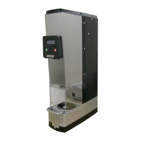
SmartServe™ Drink Mixers
MIC2000
BIC2000
– NOTICE –
www.commercial.hamiltonbeach.com
520008300
08/14
Advertisement
Table of Contents
Troubleshooting

Related Manuals for Hamilton Beach SmartServe MIC2000


Summary of Contents for Hamilton Beach SmartServe MIC2000
- Page 1 Procedures for which you do not have the necessary tools, instruments, and skills should be performed by a trained Service Technician. Reproduction or other use of this Manual, without the express written consent of Hamilton Beach, is prohibited. 520008300 www.commercial.hamiltonbeach.com...
-
Page 2: Table Of Contents
Linear Actuator Assembly.....................41 48VDC Power Supply ......................44 Control Board Assembly.......................47 Sensor Assembly (Home Position)..................50 Sensor Assembly (Cup Present) ..................52 Cup-In-Place Sensor (Infrared) ....................55 Shield Door Sensor ......................60 Wash Chamber Assembly ....................65 Page 2 of 92 © Hamilton Beach Brands, 2014 520008300 08/14... - Page 3 SmartServe™ Drink Mixers Service Manual Water Solenoid ........................70 Wash Chamber Gasket ......................72 Water Manifold (MIC2000 Only) ...................74 Cup Shield Gasket .......................75 REPLACEMENT PARTS LIST SHIELD DOOR ASSEMBLY & PANELS ................76 OPERATOR INTERFACE PANEL ASSEMBLY ..............78 CONTROL BOARD ASSEMBLY AND SENSORS ...............80 LINEAR ACTUATOR, MOTOR, &...
-
Page 4: General
SmartServe™ Drink Mixers Service Manual SAVE THESE INSTRUCTIONS REVIEW ALL SERVICE INFORMATION IN THE APPROPRIATE SERVICE MANUAL AND TECHNICAL SHEETS BEFORE BEGINNING REPAIRS. Pride and workmanship go into every product to provide our customers with quality products. It is possible, however, that during its lifetime, a product may require service. Products should be serviced only by a qualified service technician who is familiar with the safety procedures required in the repair and who is equipped with the proper tools, parts, testing instruments, and the appropriate service manual. -
Page 5: Technical Services
CAUTION Hamilton Beach will not be responsible for any injury or property damage from improper service procedures. If performing service on your own product, you must assume responsibility for any personal injury or property damage that may result. -
Page 6: Tools And Materials
SmartServe™ Drink Mixers Service Manual Tools and Materials CAUTION Do not use power tools to remove hardware. Damage to the hardware or the machine may occur. Do not lose hardware. • Standard set of hand tools • VOM with AC current tester (any quality VOM with a sensitivity of at least 20,000 ohms per volt can be used) •... -
Page 7: Preventative Maintenance
SmartServe™ Drink Mixers Service Manual Preventative Maintenance To keep the machine operating properly, it is essential that the machine is cleaned regularly. Whenever service is performed on the machine, a visual inspection of the components should be performed to ensure optimal operating conditions. General Cleaning The shield will need to be cleaned depending on the application and how many cycles are completed in a given period. -
Page 8: Sanitizing
SmartServe™ Drink Mixers Service Manual Sanitizing The SmartServe™ must be sanitized before daily use. Wash SmartServe™ following instructions in “General Cleaning.” Sanitize using 1 Tablespoon (15 mL) of bleach per 1 gallon (3.8 liter) of clean, cool water (60°F/16°C), mixed according to the instructions on the bleach. (If using a sanitizing solution other than bleach, test the concentration using commercial test strips. -
Page 9: Troubleshooting
SmartServe™ Drink Mixers Service Manual Component Functions The motor is used to turn the blade assembly. It receives power Motor through the control board. The linear actuator is used to lower and raise the motor and cup guard/shield assembly during use. It receives power and is controlled Linear Actuator by the control board. -
Page 10: Control Board Connections
SmartServe™ Drink Mixers Service Manual Control Board Connections Control Board 1 (Solenoid and Sensor) Control Board 2 (Linear Motor) Control Board 3 (Command Logic) Control Board 4 (Motor Power) Control Board Assembly Jumper To Board 2 (2-Pin) From Power Supply (V- &... - Page 11 SmartServe™ Drink Mixers Service Manual Control Board 1 (Solenoid and Sensor) Control Board 2 (Linear Motor) Control Board 3 (Command Logic) Control Board 4 (Motor Power) Control Board Assembly Jumper From Board 1 (2-Pin) To Linear Actuator Motor Control Board 2 (Linear Motor) Page 11 of 92 Troubleshooting 520008300 08/14...
- Page 12 SmartServe™ Drink Mixers Service Manual Control Board 1 (Solenoid and Sensor) Control Board 2 (Linear Motor) Control Board 3 (Command Logic) Control Board 4 (Motor Power) Control Board Assembly Jumper From Board 4 (8-Pin) To Wash Chamber Sensor To second Shield Interface Display Board (Door) Sensor and Jumper...
- Page 13 SmartServe™ Drink Mixers Service Manual Control Board 1 (Solenoid and Sensor) Control Board 2 (Linear Motor) Control Board 3 (Command Logic) Control Board 4 (Motor Power) Control Board Assembly (White) (Black) From Main Breaker Switch Jumper To Board 3 (8-Pin) (Black) Motor (White)
-
Page 14: Interface Display Board Connections
SmartServe™ Drink Mixers Service Manual Interface Display Board Connections To Control To Control Board 3 (5-Pin) Board 1 (6-Pin) Lock Tab Breaker USB Port Switch Page 14 of 92 Troubleshooting 520008300 08/14... -
Page 15: Power Supply Connections
SmartServe™ Drink Mixers Service Manual Power Supply Connections 48 VDC POWER SUPPLY (Black) (White) (Black/Red) (Red) Page 15 of 92 Troubleshooting 520008300 08/14... -
Page 16: Wiring Diagrams
SmartServe™ Drink Mixers Service Manual Wiring Diagrams MIC2000 Page 16 of 92 Troubleshooting 520008300 08/14... -
Page 17: Bic2000
SmartServe™ Drink Mixers Service Manual BIC2000 Page 17 of 92 Troubleshooting 520008300 08/14... -
Page 18: Water And Valve Diagrams
SmartServe™ Drink Mixers Service Manual Water and Valve Diagrams MIC2000 Check Valve Stem Tee 1/4” OD TUBE Sanitize Port 3/16” OD TUBE 4 Black Valve Black 2 3 White Water Valve Delivery to Cup White 1 To Wash Chamber WATER INLET BIC2000 Black 2 Valve... -
Page 19: Component Testing
SmartServe™ Drink Mixers Service Manual Component Testing COMPONENT OPERATING RESISTANCE TEST VOLTAGE (Approximate) LOCATION Motor 85 VDC 4.4 Ω WHT to BLK Linear Actuator 48 VDC 2.7 Ω RED/WHT to RED 2.7 Ω GRN/WHT to GRN Power Supply 120 VAC L to N 48 VDC V- to V+... - Page 20 SmartServe™ Drink Mixers Service Manual SYMPTOM POSSIBLE CAUSE CORRECTIVE ACTION Product too thin after Product is too warm or Check temperature of freezer blending (MIC Only) being stored at incorrect unit. Adjust as necessary. temperature Improperly calibrated water Use operator interface panel to check WATER SCALE percent- age.
- Page 21 SmartServe™ Drink Mixers Service Manual SYMPTOM POSSIBLE CAUSE CORRECTIVE ACTION Clicking noise at start of Stepper motor lead screw Apply lubricant to stepper mo- blend cycle needs lubrication tor lead screw. Linear actuator slides should only be cleaned, never lubricated. Water delivery coil tube Reroute or move coil tube and cover getting caught while...
-
Page 22: Error Code Troubleshooting
SmartServe™ Drink Mixers Service Manual Error Code Troubleshooting If Operator Interface Panel displays an error code message, press STOP button repeatedly until error code message clears or power down SmartServe™ and turn back on to reboot. If error code message remains, use the table below: ERROR CODE MESSAGE POSSIBLE CAUSE CORRECTIVE ACTION... - Page 23 SmartServe™ Drink Mixers Service Manual ERROR CODE MESSAGE POSSIBLE CAUSE CORRECTIVE ACTION Motor Control Error Shake cup not in place Ensure shake cup is placed inside cup holder properly. Obstruction in safety shield Ensure there are no obstruc- tions inside safety shield pre- venting machine from rinsing or fl...
- Page 24 SmartServe™ Drink Mixers Service Manual ERROR CODE MESSAGE POSSIBLE CAUSE CORRECTIVE ACTION Communication Error Shake cup not in place Ensure shake cup is placed inside cup holder properly. Disrupted blend, rinse, Ensure there were no dis- fl ush, wash, or sanitize ruptions during blend, rinse, cycles.
- Page 25 Press STOP button repeat- rebooted edly until error code mes- sages clear or power down SmartServe™ and turn back on to reboot. Hamilton Beach SmartServe™ needs to be Press STOP button repeat- Commercial (screen froze, rebooted edly until error code mes- touch pad doesn’t work)
-
Page 26: Safety Shield Assembly
SmartServe™ Drink Mixers Service Manual Safety Shield Assembly The safety shield assembly is located on the front of the machine. The assembly includes a shield door that can be serviced separately. A magnet embedded in the assembly interacts with the shield sensor. Some models have two door magnets and sensors. The machine will not operate if the safety shield assembly is not installed and the door is not closed properly. - Page 27 SmartServe™ Drink Mixers Service Manual To install the safety shield assembly: Slide the safety shield assembly (3) onto the machine (4). Install a thumb screw (2) on each side of the safety shield assembly (3). Plug in the power cord to the machine, turn the control panel power switch (1) to the RESET position, and verify machine operates.
-
Page 28: Top Cover
SmartServe™ Drink Mixers Service Manual Top Cover The top cover is located on the top of the machine. Removal of the top cover allows access to various components of the machine. WARNING To avoid risk of serious injury or death, disconnect power to the machine before cleaning, servicing, or removing parts. - Page 29 SmartServe™ Drink Mixers Service Manual To install the top cover: Place the top cover (4) onto the machine (3) as shown. Install two screws (2) on each side of the machine (3). Plug in the power cord to the machine, turn the control panel power switch (1) to the RESET position, and verify machine operates.
-
Page 30: Operator Interface Panel Assembly
SmartServe™ Drink Mixers Service Manual Operator Interface Panel Assembly The operator interface panel assembly is located on the front of the machine and is used to operate the machine. The assembly has a breaker switch, control board, touch pad, and access door that are serviceable. - Page 31 SmartServe™ Drink Mixers Service Manual Remove four screws (4) from the panel (5). Carefully lift the panel (5) from the machine. Mark and disconnect two connectors (6) from the interface control board (7). Mark and disconnect three wires (8) from the breaker switch (9). To install the operator interface panel assembly: Ensure the panel gasket (10) is on the machine.
-
Page 32: Breaker Switch
SmartServe™ Drink Mixers Service Manual Breaker Switch The breaker switch is located on the operator interface panel and is used to turn the main power on or off. To remove the breaker switch: Remove the operator interface panel assembly (1) as outlined in this manual. Depress the tabs (2) on the switch (3) and remove the switch from the operator interface panel assembly (1). -
Page 33: Interface Display Board
SmartServe™ Drink Mixers Service Manual Interface Display Board The interface display board is located on the operator interface panel and is used to display information to the user and relay input commands to the control board assembly. To remove the interface display board: Remove the operator interface panel assembly (1) as outlined in this manual. -
Page 34: Touch Pad
SmartServe™ Drink Mixers Service Manual Touch Pad The touch pad is located on the operator interface panel and is used by the operator to control the machine. To remove the touch pad: Remove the operator interface panel assembly (1) as outlined in this manual. Disconnect the touch pad ribbon cable (2) from the display board (3). -
Page 35: Cup Guard & Shield Assembly
SmartServe™ Drink Mixers Service Manual Cup Guard & Shield Assembly The cup guard & shield assembly is lowered over the cup during operation and cleaning cycles. It is mounted on the motor assembly. To remove the cup guard & shield assembly: Remove the safety shield assembly as outlined in this manual. - Page 36 SmartServe™ Drink Mixers Service Manual Raise the cup guard and shield assembly (7) and place a support block (8) under the shield block (9). Remove two flange nuts (10), shield block (9), and cup guard and shield assembly (7) from the motor assembly (11). To install the cup guard &...
- Page 37 SmartServe™ Drink Mixers Service Manual Remove the wire tie (3) holding the wrap (2) to the side panel (4). Position the wrap (2) on the machine and secure the wrap with six screws (1). NOTE: Ensure the wire harness is positioned in a way to avoid interference with the movement of the cup guard and shield assembly.
-
Page 38: Motor Assembly
SmartServe™ Drink Mixers Service Manual Motor Assembly The motor assembly is used to turn the blade assembly. It receives power through the control board. To remove the motor assembly: NOTE: This removal procedure is for the BIC2000. The removal procedure for the MIC2000 is similar and will require the water supply to be disconnected and the system purged before removing the motor assembly. - Page 39 SmartServe™ Drink Mixers Service Manual Remove four screws (10) and harness cover (11) from motor assembly (6). Pull six wires (7) from the motor assembly (6). To install the motor assembly: Feed six wires (7) into the motor assembly (6). Secure the wire harness in place with the harness cover (11) and four screws (10).
- Page 40 SmartServe™ Drink Mixers Service Manual Secure the wires (7) with two clamps (5) on the motor assembly (6). NOTE: On the MIC2000, connect the spiral water line to the water delivery manifold after step 5. Pull up on the motor cord (1) just under the top pulley (2). This will raise the lower pulley (3).
-
Page 41: Linear Actuator Assembly
SmartServe™ Drink Mixers Service Manual Linear Actuator Assembly The linear actuator assembly is used to lower and raise the motor carriage during use. To remove the linear actuator assembly: Remove the safety shield assembly as outlined in this manual. Remove the top cover as outlined in this manual. Remove three screws (1) from each side of the machine. - Page 42 SmartServe™ Drink Mixers Service Manual NOTE: On the MIC2000, disconnect the spiral water line from the water delivery manifold before step 9. Remove two screws (11) and lift motor assembly (12) from the linear motor assembly (13). Allow the motor assembly to hang by the motor cord. 10.
- Page 43 SmartServe™ Drink Mixers Service Manual NOTE: On the MIC2000, connect the spiral water line to the water delivery manifold after step 2. Connect the linear motor connector (10) to the control board (9). Position the control board (9) on the standoffs and install lockwashers (8) and nuts (7). NOTE: Secure any loose wires with wire ties as required.
-
Page 44: 48Vdc Power Supply
SmartServe™ Drink Mixers Service Manual 48VDC Power Supply The 48VDC power supply is located behind the back panel and distributes power to control board #1 and jumps to control board #2 to supply power for valves and linear actuator motor. WARNING To avoid risk of serious injury or death, disconnect power to the machine before cleaning, servicing, or removing parts. - Page 45 SmartServe™ Drink Mixers Service Manual Lift and rotate clockwise the power control assembly (5) until you are able to access the rear of the power control assembly (5). Mark and disconnect four wires (6) from the power supply (7). Remove four screws (8), washers (9), and power supply (7) from the power control assembly (5).
- Page 46 SmartServe™ Drink Mixers Service Manual Carefully position the power control assembly (5) on the four knobs (4). NOTE: Ensure all connections on the power supply and control board are secure. Replace any wire ties as required. Hand-tighten the four knobs (4). Install the back cover (3) with six screws (2).
-
Page 47: Control Board Assembly
SmartServe™ Drink Mixers Service Manual Control Board Assembly The control board assembly is located behind the back panel and controls all functions of the machine. WARNING To avoid risk of serious injury or death, disconnect power to the machine before cleaning, servicing, or removing parts. - Page 48 SmartServe™ Drink Mixers Service Manual Remove four nuts (5) and lockwashers (6) from control board (7). Position the control board (7) to the left to access and disconnect the linear motor connector (8). Position the control board (7) on the standoffs (9) and install lockwashers (6) and nuts (5).
- Page 49 SmartServe™ Drink Mixers Service Manual Remove four nuts (5) and lockwashers (6) from control board (7). Position the control board (7) to the left to connect the linear motor connector (8). Position the control board (7) on the standoffs (9) and install lockwashers (6) and nuts (5).
-
Page 50: Sensor Assembly (Home Position)
SmartServe™ Drink Mixers Service Manual Sensor Assembly (Home Position) The sensor assembly (home position) is located on the frame near the top of the machine. The sensor determines the highest position of the motor and cup guard/shield assembly. To remove the sensor assembly (home position): Remove the top cover as outlined in this manual. - Page 51 SmartServe™ Drink Mixers Service Manual To install the sensor assembly (home position): Push the sensor assembly (5) into the hole in the frame (6). NOTE: Route the wire harness for the sensor to the control board in a way that will avoid any chance of pinching or fraying of the wires.
-
Page 52: Sensor Assembly (Cup Present)
SmartServe™ Drink Mixers Service Manual Sensor Assembly (Cup Present) The sensor assembly (cup present) is located on the frame near the motor assembly. The sensor determines the lowest position of the motor and cup guard/shield assembly. To remove the Sensor Assembly (Cup Present): Remove the safety shield assembly as outlined in this manual. - Page 53 SmartServe™ Drink Mixers Service Manual Use a screwdriver to depress the tabs on the side of the sensor assembly (9) and push the sensor assembly (9) through the hole in the frame (10) and remove the sensor assembly (9). The black plastic housing is part of the sensor assembly. To install the sensor assembly (cup present): Push the sensor assembly (9) into the hole in the frame (10).
- Page 54 SmartServe™ Drink Mixers Service Manual Remove the wire tie (3) holding the wrap (2) to the side panel (4). Position the wrap (2) on the machine and secure the wrap (2) with six screws (1). NOTE: Ensure the wire harness is positioned in a way to avoid interference with the movement of the cup guard and shield assembly.
-
Page 55: Cup-In-Place Sensor (Infrared)
SmartServe™ Drink Mixers Service Manual Cup-In-Place Sensor (Infrared) The cup-in-place sensor is located on the front of the machine in the mixing chamber. To remove the cup-in-place sensor: Remove the safety shield assembly as outlined in this manual. Remove the top cover as outlined in this manual. Remove three screws (1) from each side of the machine. - Page 56 SmartServe™ Drink Mixers Service Manual Remove two screws (8), washer (9), and plastic spacers (10). Remove two screws (11) from the top of the wash chamber cover (12). Remove six screws (13) from each side of the wash chamber cover (12). 10.
- Page 57 SmartServe™ Drink Mixers Service Manual 13. Grasp both sides of the wash chamber cover (12) and gently pull the ends away from the machine. NOTE: Cover back sides of wash chamber cover to avoid scratches/damage to side of machine. 14. Slide the wash chamber cover (12) forward to access the sensor (19). 15.
- Page 58 SmartServe™ Drink Mixers Service Manual Install two screws (8), washers (9), and plastic spacers (10) on the wash chamber cover (12). Install two screws (11) on the top of the wash chamber cover (12). Install six screws (13) on each side of the wash chamber cover (12). Install two screws (14) on the back of the machine.
- Page 59 SmartServe™ Drink Mixers Service Manual 10. Remove the wire tie (3) holding the wrap (2) to the side panel (4). 11. Position the wrap (2) on the machine and secure the wrap with six screws (1). NOTE: Ensure the wire harness is positioned in a way to avoid interference with the movement of the cup guard and shield assembly.
-
Page 60: Shield Door Sensor
SmartServe™ Drink Mixers Service Manual Shield Door Sensor The shield door sensor is located under the wash chamber area. A magnet in the safety shield assembly interacts with the sensor and requires that the door be closed in order for the machine to operate. - Page 61 SmartServe™ Drink Mixers Service Manual Remove two screws (8), washer (9), and plastic spacers (10). Remove two screws (11) from the top of the wash chamber cover (12). Remove six screws (13) from each side of the wash chamber cover (12). 10.
- Page 62 SmartServe™ Drink Mixers Service Manual 13. Grasp both sides of the wash chamber cover (12) and gently pull the ends away from the machine. NOTE: Cover back sides of wash chamber cover to avoid scratches/damage to side of machine. 14. Slide the wash chamber cover (12) forward and rotate as shown to access the sensor (19).
- Page 63 SmartServe™ Drink Mixers Service Manual Install two screws (8), washer (9), and plastic spacers (10) on the wash chamber cover (12). Install two screws (11) on the top of the wash chamber cover (12). Install six screws (13) on each side of the wash chamber cover (12). Install two screws (14) on the back of the machine.
- Page 64 SmartServe™ Drink Mixers Service Manual 10. Remove the wire tie (3) holding the wrap (2) to the side panel (4). 11. Position the wrap (2) on the machine and secure the wrap with six screws (1). NOTE: Ensure the wire harness is positioned in a way to avoid interference with the movement of the cup guard and shield assembly.
-
Page 65: Wash Chamber Assembly
SmartServe™ Drink Mixers Service Manual Wash Chamber Assembly The wash chamber assembly is located under the wash chamber cover. To remove the wash chamber assembly: Shut off water supply, disconnect water line from machine, and purge the system to remove water from the lines. Remove the safety shield assembly as outlined in this manual. - Page 66 SmartServe™ Drink Mixers Service Manual Remove two screws (8), washer (9), and plastic spacers (10). Remove two screws (11) from the top of the wash chamber cover (12). 10. Remove six screws (13) from each side of the wash chamber cover (12). 11.
- Page 67 SmartServe™ Drink Mixers Service Manual 14. Grasp both sides of the wash chamber cover (12) and gently pull the ends away from the machine. NOTE: Cover back sides of wash chamber cover to avoid scratches/damage to side of machine. 15. Slide the wash chamber cover (12) forward and rotate as shown. 16.
- Page 68 SmartServe™ Drink Mixers Service Manual NOTE: Route the wire harness for the sensor to the control board in a way that will avoid any chance of pinching or fraying of the wires. Replace any wire ties as required. Connect sensor connector (17) to the control board (18). Install the back cover (16) with six screws (15).
- Page 69 SmartServe™ Drink Mixers Service Manual 11. Install the cup shield (5) on the cup guard and shield assembly (7) until the tab (6) locks into place. 12. Remove the wire tie (3) holding the wrap (2) to the side panel (4). 13.
-
Page 70: Water Solenoid
SmartServe™ Drink Mixers Service Manual Water Solenoid The MIC2000 has two water solenoids and the BIC2000 only has one water solenoid. The BIC2000 is the model shown. Removal procedure for both is similar. See the Water and Valve Diagrams for hose and valve positions. NOTE: Make note of water flow indicators on solenoid (small arrow on underside of intake side) and water flow directions on solenoid support (IN, OUT, and REAR stamped into metal to indicate flow direction and solenoid support orientation) to install new solenoid and water lines... - Page 71 SmartServe™ Drink Mixers Service Manual Remove six screws (2) and back cover (3) from machine. Disconnect water line (4) from solenoid (5). Disconnect inlet water line (6) from inlet port (7). Remove two nuts (8), screws (9), and solenoid support (10) from the frame. NOTE: Remove any wire ties as required.
-
Page 72: Wash Chamber Gasket
SmartServe™ Drink Mixers Service Manual Reconnect the main water line to the machine. Plug in the power cord to the machine, turn the control panel power switch (1) to the RESET position, and verify machine operates. Wash Chamber Gasket The wash chamber gasket provides a seal to prevent water from leaking from the wash chamber. - Page 73 SmartServe™ Drink Mixers Service Manual To install the wash chamber gasket: NOTE: Ensure all old gasket material is removed before installing a new gasket. Place the gasket (6) on the wash chamber assembly (5). Place the gasket cover (4) on the gasket (6) and wash chamber assembly (5). Install screw (2) and screw (3).
-
Page 74: Water Manifold (Mic2000 Only)
SmartServe™ Drink Mixers Service Manual Water Manifold (MIC2000 Only) The water manifold is located near the top of the machine. To remove the water manifold: Shut off water supply, disconnect water line from machine, and purge the system to remove water from the lines. Remove the top cover as outlined in this manual. -
Page 75: Cup Shield Gasket
SmartServe™ Drink Mixers Service Manual Cup Shield Gasket The cup shield gasket is located in the shield assembly. To replace the cup shield gasket: Remove the shield assembly as outlined in this manual. Place the shield assembly (1) on a suitable work surface. From the top, push the shaft seal (2) through the cup gasket (3). -
Page 76: Replacement Parts List
SmartServe™ Drink Mixers Service Manual 1 8 1 9 fig_1_HB SHIELD DOOR ASSEMBLY & PANELS Page 76 of 92 Replacement Parts List 520008300 08/14... - Page 77 SmartServe™ Drink Mixers Service Manual SHIELD DOOR ASSEMBLY & PANELS ITEM # PART NO. NAME OF PART AMT. 990167800 Tool – Blade Removal ......................1 990172500 Gasket – Base ........................1 Panel – Right Side (Painted)....................1 Bracket – Hold Down ......................2 Screw ..........................
-
Page 78: Operator Interface Panel Assembly
SmartServe™ Drink Mixers Service Manual 5 - 6 fig_2_HB OPERATOR INTERFACE PANEL ASSEMBLY Page 78 of 92 Replacement Parts List 520008300 08/14... - Page 79 SmartServe™ Drink Mixers Service Manual OPERATOR INTERFACE PANEL ASSEMBLY ITEM # PART NO. NAME OF PART AMT. 990153200 Enclosure – Operator Interface Assembly ................1 990153290 Display Board – Interface..................... 1 990153280 Switch – Breaker (Control Panel)..................1 990153210 Touch Pad (Generic) ......................1 990153270 Door –...
-
Page 80: Control Board Assembly And Sensors
SmartServe™ Drink Mixers Service Manual 3 - 4 fig_3_HB CONTROL BOARD ASSEMBLY AND SENSORS Page 80 of 92 Replacement Parts List 520008300 08/14... - Page 81 SmartServe™ Drink Mixers Service Manual CONTROL BOARD ASSEMBLY AND SENSORS ITEM # PART NO. NAME OF PART AMT. Screw ........................... 6 Panel – Back ........................1 990150000 Control Board Assembly (120V)................... 1 990152800 Control Board Assembly (230V)................... 1 Knob ............................. 4 Nut –...
-
Page 82: Linear Actuator, Motor, & Cup Guard (Bic2000)
SmartServe™ Drink Mixers Service Manual S e e M O T O R A S S E M B L Y 1 2 0 V - 9 9 0 1 4 8 7 0 0 2 3 0 V - 9 9 0 1 4 8 8 0 0 1 3 - 1 4 fig_4_HB LINEAR ACTUATOR, MOTOR, &... - Page 83 SmartServe™ Drink Mixers Service Manual LINEAR ACTUATOR, MOTOR, & CUP GUARD (BIC2000) ITEM # PART NO. NAME OF PART AMT. 990152700 Spring – Festoon........................1 990148600 Lower Pulley Assembly ......................1 Relief – Strain ........................1 990149500 Upper Pulley Assembly ......................1 990149600 Cord –...
-
Page 84: Linear Actuator, Motor, & Cup Guard (Mic2000)
SmartServe™ Drink Mixers Service Manual S e e M O T O R A S S E M B L Y 1 2 0 V - 9 9 0 1 4 8 7 0 0 2 3 0 V - 9 9 0 1 4 8 8 0 0 1 2 - 1 3 fig_8_HB LINEAR ACTUATOR, MOTOR, &... - Page 85 SmartServe™ Drink Mixers Service Manual LINEAR ACTUATOR, MOTOR, & CUP GUARD (MIC2000) ITEM # PART NO. NAME OF PART AMT. 990152700 Spring – Festoon........................1 990148600 Lower Pulley Assembly ......................1 Relief – Strain ........................1 990149500 Upper Pulley Assembly ......................1 990149600 Cord –...
-
Page 86: Motor Assembly
SmartServe™ Drink Mixers Service Manual 6 - 7 fig_5_HB MOTOR ASSEMBLY Page 86 of 92 Replacement Parts List 520008300 08/14... - Page 87 SmartServe™ Drink Mixers Service Manual MOTOR ASSEMBLY (120V – 990148700) (230V – 990148800) ITEM # PART NO. NAME OF PART AMT. Motor Housing ........................1 990171000 Bushing – Rod (Lower) ......................2 990171200 Pad – Motor Mount (Lower) ....................1 990170900 Bushing –...
-
Page 88: Wash Chamber & Water Lines (Bic2000)
SmartServe™ Drink Mixers Service Manual fig_7_HB WASH CHAMBER & WATER LINES (BIC2000) Page 88 of 92 Replacement Parts List 520008300 08/14... - Page 89 SmartServe™ Drink Mixers Service Manual WASH CHAMBER & WATER LINES (BIC2000) ITEM # PART NO. NAME OF PART AMT. 990148400 Wash Chamber Assembly (Includes Items 2, 3, & Sensors) ..........1 990152600 Adapter – Drain ........................1 990152500 Gasket – Wash Chamber Manifold ..................1 Screw ...........................
-
Page 90: Wash Chamber & Water Lines (Mic2000)
SmartServe™ Drink Mixers Service Manual fig_6_HB WASH CHAMBER & WATER LINES (MIC2000) Page 90 of 92 Replacement Parts List 520008300 08/14... - Page 91 SmartServe™ Drink Mixers Service Manual WASH CHAMBER & WATER LINES (MIC2000) ITEM # PART NO. NAME OF PART AMT. 990148400 Wash Chamber Assembly (Includes Items 2, 3, & Sensors) ..........1 990152600 Adapter – Drain ........................1 990152500 Gasket – Wash Chamber Manifold ..................1 Screw ...........................
- Page 92 520008300 www.commercial.hamiltonbeach.com 08/14...