Table of Contents
Advertisement
Quick Links
Download this manual
See also:
User Manual
1.
READ these instructions.
2.
KEEP these instructions.
3.
HEED all warnings.
4.
FOLLOW all instructions.
5.
DO NOT use this apparatus near water.
6.
CLEAN ONLY with dry cloth.
7.
DO NOT block any ventilation openings. Install in accordance with the manu-
facturer's instructions.
8.
DO NOT install near any heat sources such as radiators, heat registers, stoves,
or other apparatus (including amplifiers) that produce heat.
9.
DO NOT defeat the safety purpose of the polarized or grounding-type plug. A
polarized plug has two blades with one wider than the other. A grounding type
plug has two blades and a third grounding prong. The wider blade or the third
prong are provided for your safety. If the provided plug does not fit into your out-
let, consult an electrician for replacement of the obsolete outlet.
10.
PROTECT the power cord from being walked on or pinched, particularly at plugs,
convenience receptacles, and the point where they exit from the apparatus.
11.
ONLY USE attachments/accessories specified by the manufacturer.
DESCRIPTION
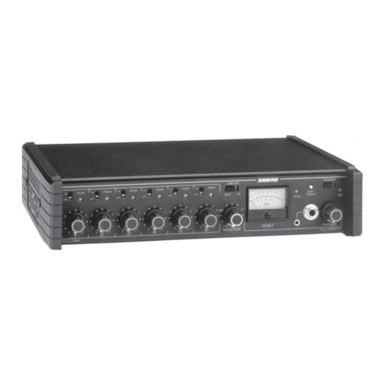
The Shure M367 is a portable, six-input, two-output (mono),
battery-powered microphone and line level mixer/preamplifier. Its
transformer-isolated design, low-noise performance, and compact
and rugged construction make the M367 an ideal choice for studio
and mobile broadcast, electronic news gathering (ENG), and
electronic field production (EFP) applications.
This versatile mixer can also be used for the following:
•
Digital transmission links
•
Digital video/audio recording media (ISDN, hard disk
recording, and DAT)
•
Sound reinforcement
The M367 comes with rubber feet, detachable power cord, and
spare power line fuse. It can be rack mounted using the optional
Model A367R rack mount kit.
FEATURES
•
Six selectable mic/line inputs
•
Selectable mic/line output and dedicated line output
•
Transformer-balanced inputs and outputs for superior rejection
of RFI and electromagnetic hum
•
Professional mechanical VU meter–LED backlighting for high
reliability, no lamp replacement
©2008 Shure Incorporated
27C8511 (Rev. 5)
SIX CHANNEL MICROPHONE MIXER
! IMPORTANT SAFETY INSTRUCTIONS !
12.
13.
14.
15.
16.
17.
18.
19.
20.
•
•
•
•
ADDITIONAL FEATURES
•
•
•
•
•
•
•
•
•
Model M367 User Guide
USE only with a cart, stand, tripod, bracket, or table
specified by the manufacturer, or sold with the
apparatus. When a cart is used, use caution when
moving the cart/apparatus combination to avoid
injury from tip-over.
UNPLUG this apparatus during lightning storms or when unused for long periods of
time.
REFER all servicing to qualified service personnel. Servicing is required when the
apparatus has been damaged in any way, such as power-supply cord or plug is dam-
aged, liquid has been spilled or objects have fallen into the apparatus, the apparatus
has been exposed to rain or moisture, does not operate normally, or has been
dropped.
DO NOT expose the apparatus to dripping and splashing. DO NOT put objects filled
with liquids, such as vases, on the apparatus.
The MAINS plug or an appliance coupler shall remain readily operable.
The airborne noise of the apparatus does not exceed 70dB (A).
Apparatus with CLASS I construction shall be connected to a MAINS socket outlet
with a protective earthing connection.
To reduce the risk of fire or electric shock, do not expose this apparatus to rain or
moisture.
Do not attempt to modify this product. Doing so could result in personal injury
and/or product failure.
Headphone monitoring 3.5 mm, (1/4 in.)
Output peak limiter with switchable threshold and bi-colored
LED indicator
Peak indicator LED, and switchable low-cut filters on each input
1/4 in. return monitor input
AC power or (2) 9V battery operation
48 Vdc or 12 V phantom power for condenser microphones
1 kHz tone oscillator
• Mutes all input channels when activated
• Tone level control is on the master
Wide–range input gain controls handle hot signal levels without
attenuators
Customized operation via internal DIP switches, trim pots, and
optional alternate wiring
Battery check switch and low battery warning indication
Power-on LED
Input expansion via mix bus jack to link M367s or other mixers
Rugged all metal chassis with protective end caps
Detachable AC power cord
Printed in U.S.A.
Advertisement
Table of Contents

Related Manuals for Shure M367


Summary of Contents for Shure M367
- Page 1 The Shure M367 is a portable, six-input, two-output (mono), battery-powered microphone and line level mixer/preamplifier. Its transformer-isolated design, low-noise performance, and compact and rugged construction make the M367 an ideal choice for studio and mobile broadcast, electronic news gathering (ENG), and electronic field production (EFP) applications.
-
Page 2: Front Panel Controls And Indicators
Ñ Ñ Ñ Ñ Ñ Ñ Ñ Ñ Ñ Ñ Ñ Ñ Ñ Ñ Ñ Ñ Ñ Ñ Ñ Ñ Ñ M367 Ñ Ñ Ñ Ñ Ñ Ñ Ñ Ñ Ñ Ñ Ñ Ñ Green = power on = low batteries (about 30 minutes of Flashing... -
Page 3: Rear Panel Connectors And Controls
M367 can be adjusted without affecting the other mixer’s output. NOTE The output level of each M367 mixer drops by 6 dB when connected through the MIX BUS, increase the Master Gain to compensate. For a balanced mix bus connection between two M367s, use a mix bus cable with two 1/4 in. - Page 4 AC OPERATION Use the supplied power adapter to connect the M367 to a power outlet. M367: 100-120 VAC, 50/60 Hz M367E: 220-240 VAC, 50/60 Hz The operating voltage can be switched internally (see Internal Modifiable Functions). NOTE Appliance inlet is the main disconnect device (to power off the M367, you must unplug the power supply).
-
Page 5: Specifications
22°C (72°F); input signal 1 kHz; internal DIP switches 1–7 open; Power switch on; Mic/Line switches to Line; low-cut switches to flat; Limiter out; Phantom power off; Mix Bus to M367; channel 1 gain full CW; channel 2 through 6 full CCW; Master full CW; Phones level full CCW;... -
Page 6: Optional Accessories
REPLACEMENT PARTS Foot Kit (4 in kit) ... 90S8100 M367 Fuse, 0.125 A, 250 V ... 80E380 M367E Fuse, 0.063 A, 250 V ... 80G380 Knob Master ... 95A8238 Channel Gain, Phones ... 95B8238 Line (Power) Cord M367 ... 95A8389 M367E... -
Page 7: Internal Adjustments
4. Adjust the 1 kHz tone oscillator level with the Master gain trol until the ac voltmeter reading is at the level desired 5. With the M367 top cover removed, adjust the VU Level Cali- bration trim pot R684 with a screwdriver until the VU Meter reads 0. -
Page 8: Internal Modifiable Functions
Note that all modifications can be performed without removing the main PC board. 5. Reassemble M367 by performing above steps in reverse, assembling the Phillips screws in the order indicated on the upper front and upper rear PC boards. - Page 9 Ñ Ñ Ë Ë Ë If using a true stereo feed to drive the M367 Monitor In and another stereo device, the source impedance must be 20 Ω or less to maintain at least 40 dB separation in the stereo device.
- Page 10 CHANGING LIMITER RELEASE TIME TO ONE SECOND Remove resistor R741 (about 15 mm behind ribbon cable assembly W813). CHANGING LIMITER THRESHOLD PRESETS 1. Select the equivalent resistor values for the desired limiter thresholds from the following table. Then fill in the following work sheet with the resistor selections.
- Page 11 United States, Canada, Latin America, Caribbean: 5800 W. Touhy Avenue, Niles, IL 60714-4608, U.S.A. Phone: 847-600-2000 U.S. Fax: 847-600-1212 Intl Fax: 847-600-6446 Europe, Middle East, Africa: Shure Europe GmbH, Phone: 49-7131-72140 Fax: 49-7131-721414 Asia, Pacific: Shure Asia Limited, Phone: 852-2893-4290 Fax: 852-2893-4055...