
Related Manuals for Panasonic SF-C21


Summary of Contents for Panasonic SF-C21
- Page 1 Safety Control Unit SF-C21 Instruction Manual WUME-SFC21-4 2016.1 panasonic.net/id/pidsx/global...
- Page 2 (MEMO) © Panasonic Industrial Devices SUNX Co., Ltd. 2016...
- Page 3 Thank you for purchasing Panasonic Industrial Devices SUNX’s Safety Control Unit SF-C21. Please read this instruction manual carefully and thoroughly for the correct and optimum use of this device. Kindly keep this manual in a convenient place for quick reference.
-
Page 4: Table Of Contents
3-8-4 Error Codes···········································································33 3-8-5 Address Map ·········································································34 3-8-6 Message Format ····································································35 3-8-7 Function Code ·······································································36 3-9 USB Communication ·································································· 38 3-10 Logic Selection Function ···························································· 39 3-11 OFF Delay Time Selection Function·············································· 47 © Panasonic Industrial Devices SUNX Co., Ltd. 2016... - Page 5 Device ····················································································· 89 5-9-1 Creating and Editing Logic ·······················································89 5-9-2 Saving a Logic File and Transferring it to this Device ·····················89 5-10 Create a Logic ········································································· 90 5-10-1 Create a Logic ·····································································90 © Panasonic Industrial Devices SUNX Co., Ltd. 2016...
- Page 6 Chapter 7 Troubleshooting ······························································ 115 Chapter 8 Specifications / Dimensions ·············································· 117 8-1 Specifications ·········································································· 117 8-2 Dimensions ············································································· 120 Chapter 9 Others ·········································································· 121 9-1 Glossary················································································· 121 9-2 CE Marking Declaration of Conformity ·········································· 122 © Panasonic Industrial Devices SUNX Co., Ltd. 2016...
-
Page 7: Chapter 1 Introduction
■ Before using this device, check whether the device performs properly with the functions and capabilities as per the design specifications. ■ In case of disposal, dispose this device as an industrial waste. © Panasonic Industrial Devices SUNX Co., Ltd. 2016... - Page 8 ● Clean this device with a clean cloth. Do not use any volatile chemicals. ♦ Others ● Never modify this device. Failure to follow this precaution may cause the device to mal- function, possibly resulting in a death or serious injury. © Panasonic Industrial Devices SUNX Co., Ltd. 2016...
-
Page 9: Applicable Standards / Regulations
1-4 Confirmation of Packed Contents □ SF-C21 1 pc. □ Quick Instruction Manual (Japanese, English, Chinese) 1 pc. each language © Panasonic Industrial Devices SUNX Co., Ltd. 2016... -
Page 10: Chapter 2 Before Using This Device
4, PLe). (4) Safety categories 2, 3, and 4 available Selecting logics and connecting various types of safety devices can construct systems avail- able for Categories 2, 3, and 4 of ISO 13849-1. © Panasonic Industrial Devices SUNX Co., Ltd. 2016... - Page 11 (monitoring of cross short fault). In addition, self-diagnosis, e.g., memory diagnosis and cir- cuit diagnosis, is performed. (9) Installation according to use applications 35mm width DIN rail or M4 round head screw (length: 12mm or more) is available for instal- lation. © Panasonic Industrial Devices SUNX Co., Ltd. 2016...
-
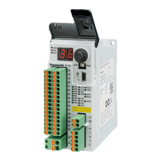
Page 12: Part Description
Interlock 1 / 2 indicator (Yellow) INT1, INT2 When interlock is ineffective: turns OFF When output at ON state: lights up in orange Muting indicator (Orange) MUTE When output at OFF state: turns OFF © Panasonic Industrial Devices SUNX Co., Ltd. 2016... -
Page 13: Terminal Arrangement
When a device (such as light curtain) requiring power supply to inputs is connected, power is supplied from internal power supply. This device does not operate when power is supplied from external power supply. © Panasonic Industrial Devices SUNX Co., Ltd. 2016... -
Page 14: Confirming Product Information
2-4-1 Version-related Information The versions of SF-C21 software and software tool “Configurator SF-C” have been changed due to addition / change of functions. The added / changed functions are supported by the versions shown in the table below. -
Page 15: Mounting
When installing this device, make sure that it is correctly oriented. The device must be installed vertically with its indicators and terminal blocks facing the operator side in order to ensure heat dissipation. Installed in vertically Horizontally installed Sideways installed reversed orientation © Panasonic Industrial Devices SUNX Co., Ltd. 2016... -
Page 16: Installation Space
100mm or more away from the surfaces of the device. When installing the unit behind the doors of the control board, be especially careful to secure clearances as above. 100mm or more SF-C21 Other devices © Panasonic Industrial Devices SUNX Co., Ltd. 2016... - Page 17 Mounting To connect the software tool and cables, keep a space of 170mm or more away from the instal- lation surface of this device. 170mm or more SF-C21 © Panasonic Industrial Devices SUNX Co., Ltd. 2016...
-
Page 18: Installation To And Removal From A Din Rail
Step 4 Remove the control unit by pulling its lower side while maintaining it in the pushed-up position (step 3). CAUTION Do not attempt to pull the control unit without first drawing out the DIN rail stopper or the nail will break. © Panasonic Industrial Devices SUNX Co., Ltd. 2016... -
Page 19: Installing The Unit Directly In A Control Panel Using Screws
● Ambient temperature: -10 to +55°C ● Ambient humidity: 30 to 85% RH (No dew condensation) ● Pollution degree: 2 ● Overvoltage category: II or lower ● Usable altitude: 2,000m above sea level or lower © Panasonic Industrial Devices SUNX Co., Ltd. 2016... -
Page 20: Wiring
ON, or turn ON the external power supply first. Delay in power ON to the external power supply locks out this device, displaying “ ” in the 7-segment indicator (red). © Panasonic Industrial Devices SUNX Co., Ltd. 2016... -
Page 21: I/O Circuit Diagrams
IN2 (4, 6, 8) − 4.7kΩ OUT1(3) MUTE1 MUTE2 OUT2(4) Load − *1: Wired when muting function and override function are used. <Reference> KA, KB: External device (Forced guided relay, magnetic contactor, monitored valve, etc.) © Panasonic Industrial Devices SUNX Co., Ltd. 2016... - Page 22 Approx. 18ms Approx. 200μs Control output 1 (OUT1) Approx. 4.5ms Approx. 200μs Control output 1 (OUT2) Approx. 4.5ms Approx. 200μs Control output 2 (OUT3) Approx. 4.5ms Approx. 200μs Control output 2 (OUT4) © Panasonic Industrial Devices SUNX Co., Ltd. 2016...
-
Page 23: Connecting To The Terminal Block
FMC 1,5/5-ST-3,5 for RS-485 Terminal block for external FKC 2,5/2-ST 0.25-2.5 0.25-2.5 0.2-2.5 0.2-2.5 24-12 power supply <Terminal block> Manufactured by Phoenix Contact Flat-head screwdriver Lead wire Ferrule terminal Release button Insertion hole © Panasonic Industrial Devices SUNX Co., Ltd. 2016... -
Page 24: Connection Of Safety Devices
Arbitrary logics, independent of preset logic, can also be created as customizable logics. <Reference> Logics changed by the software tool or arbitrary logics created cannot be transferred to this device if their safety cannot be retained. © Panasonic Industrial Devices SUNX Co., Ltd. 2016... -
Page 25: Chapter 3 Functions
(“closed” status in the case of door switch). OFF side (“open” status in the case of door switch) cannot be monitored. Settable range Initial setting 0 (unlimited) to 60 sec. Input mismatch allowable time 1 sec. (in units of 0.1 sec.) © Panasonic Industrial Devices SUNX Co., Ltd. 2016... -
Page 26: Control Output
● Output E / F / G of diagnosis results of internal logical circuit ● Reset trigger output ● Lockout output ● Muting indicator output ● Monitor output of IN1 to 8 ● Normally OFF © Panasonic Industrial Devices SUNX Co., Ltd. 2016... -
Page 27: Interlock (Reset)
INT11 INT21 INT21 INT11 INT22 INT12 INT12 INT22 With external device monitor With external device monitor INT11 INT21 INT21 INT11 INT22 INT12 INT12 INT22 Without external device monitor Without external device monitor © Panasonic Industrial Devices SUNX Co., Ltd. 2016... -
Page 28: Partial Reset
INT11 INT21 INT11 INT21 INT12 INT22 INT12 INT22 With external device monitor With external device monitor INT11 INT21 INT11 INT21 INT12 INT22 INT12 INT22 Without external device monitor Without external device monitor © Panasonic Industrial Devices SUNX Co., Ltd. 2016... -
Page 29: Releasing Lockout
When the safety input condition of this device is satisfied, release of lockout turns the control out- put into ON status in the case of auto reset setting. To prevent unexpected startup of the machine, secure safety for the overall system. © Panasonic Industrial Devices SUNX Co., Ltd. 2016... -
Page 30: External Device Monitor
Open 10ms or less 100ms or less Control output 1 / 2 <Auto reset> 10ms or more Closed Test input Open 10ms or less 100ms or less Control output 1 / 2 © Panasonic Industrial Devices SUNX Co., Ltd. 2016... -
Page 31: Modbus Communication (Non-Safety)
SW5: OFF, SW6: OFF Communication address 2 SW5: ON, SW6: OFF Communication address 3 SW5: OFF, SW6: ON Communication address 4 SW5: ON, SW6: ON Baud rate 9,600 bps 19,200 bps Unused Unused Unused © Panasonic Industrial Devices SUNX Co., Ltd. 2016... -
Page 32: Wiring Example
Material (mm) (mm) (At 20°C) 0.5 mm Hitachi Cable, Ltd. Shielded Approx. (AWG 20) or Up to 33.4 Ω/km Polyethylene Up to 0.5 KPEV-S0.5 mm ×1P twisted pair more Belden Inc. 9207 © Panasonic Industrial Devices SUNX Co., Ltd. 2016... -
Page 33: Function Code
Error in reading holding register 3-8-4 Error Codes Configuration of communication data Office No. Function code Error code CRC-16 Error code Error code Description 0x01 Function code error 0x02 Address error 0x03 Data quantity error © Panasonic Industrial Devices SUNX Co., Ltd. 2016... -
Page 34: Address Map
OFF delay No. history (2 saves ago) 0x1402 OFF delay No. history (3 saves ago) 0x1403 OFF delay No. history (4 saves ago) 0x1404 Reset request status 0x2000 Muting condition satisfaction status 0x2001 © Panasonic Industrial Devices SUNX Co., Ltd. 2016... -
Page 35: Message Format
Message error judgment data CRC-16 (L) <Response during abnormal operation> Data Description Office No. SF-C21 equipment address Function code 0x81 Error code Error code CRC-16 (H) Message error judgment data CRC-16 (L) © Panasonic Industrial Devices SUNX Co., Ltd. 2016... -
Page 36: Function Code
Message error judgment data CRC-16 (L) <Response during abnormal operation> Data Description Office No. SF-C21 equipment address Function code 0x82 Error code Error code CRC-16 (H) Message error judgment data CRC-16 (L) © Panasonic Industrial Devices SUNX Co., Ltd. 2016... - Page 37 Message error judgment data CRC-16 (L) <Response during abnormal operation> Data Description SF-C21 equipment address Office No. Function code 0x83 Error code Error code CRC-16 (H) Message error judgment data CRC-16 (L) © Panasonic Industrial Devices SUNX Co., Ltd. 2016...
-
Page 38: Usb Communication
When this device is connected to PC via a USB cable, various information of this device can be transmitted and received by using the software tool “Configurator SF-C.” For details, refer to “Chapter 5 Software Tool.” © Panasonic Industrial Devices SUNX Co., Ltd. 2016... -
Page 39: Logic Selection Function
Open 10ms or less 100ms or less Closed Open Closed Open 10ms or less 100ms or less Closed Open Closed Open 10ms or less 100ms or less 100ms or less OUT1/2 OUT3/4 © Panasonic Industrial Devices SUNX Co., Ltd. 2016... - Page 40 10ms or less OUT1/2 OUT3/4 Muting status MUTE Override status OVERRIDE Note: Regarding the muting / override settings, refer to the factory default settings shown in “3-12 Logic Set- tings by Software Tool.” © Panasonic Industrial Devices SUNX Co., Ltd. 2016...
- Page 41 OUT1/2 OUT3/4 Muting status Muting status MUTE Override status OVERRIDE Note: Regarding the muting / override settings, refer to the factory default settings shown in “3-12 Logic Set- tings by Software Tool.” © Panasonic Industrial Devices SUNX Co., Ltd. 2016...
- Page 42 INT11/12 (Reset) Open 100ms or less 150ms to 4 sec. 150ms to 4 sec. Closed INT21/22 (Reset) Open 100ms or less 100ms or less OUT1/2 100ms or less 100ms or less OUT3/4 © Panasonic Industrial Devices SUNX Co., Ltd. 2016...
- Page 43 INT11/12 (Reset) Open 150ms to 4 sec. 150ms to 4 sec. Closed INT21/22 (Reset) Open 100ms or less 100ms or less 100ms or less OUT1/2 100ms or less 100ms or less OUT3/4 © Panasonic Industrial Devices SUNX Co., Ltd. 2016...
- Page 44 Open Within 0.5 sec. Within 0.5 sec. Closed Open Closed Open Within 100ms 10ms or less Within 100ms 10ms or less Closed Open Closed Open 10ms or less Within 100ms OUT1/2 OUT3/4 © Panasonic Industrial Devices SUNX Co., Ltd. 2016...
- Page 45 100ms or less Closed Open Closed Open 100ms or less 10ms or less Closed Open Closed Open 10ms or less 10ms or less 100ms or less 100ms or less 100ms or less OUT1/2 OUT3/4 © Panasonic Industrial Devices SUNX Co., Ltd. 2016...
- Page 46 Open 10ms or less 100ms or less 100ms or less Closed Open Closed Open 10ms or less Closed Open Closed Open 100ms or less 100ms or less 10ms or less OUT1/2 OUT3/4 © Panasonic Industrial Devices SUNX Co., Ltd. 2016...
-
Page 47: Off Delay Time Selection Function
Stop category 0 sec. 0.1 sec. 0.5 sec. 1 sec. 2 sec. 5 sec. 10 sec. 15 sec. 30 sec. 60 sec. Note: Only OUT3 / 4 can be set with this device. © Panasonic Industrial Devices SUNX Co., Ltd. 2016... -
Page 48: Logic Settings By Software Tool
1 bit / 2 bits 1 bit Communication address 1 to 247 Notes: 1) Preset logic is fixed. 2) This setting in only for parallel muting. Factory settings of customizable logics are invalid. © Panasonic Industrial Devices SUNX Co., Ltd. 2016... -
Page 49: Logic Manual Stop / Start Function
Step 2 Press the rotary switch. The logics of this device are started according to the procedure below. Step 1 Switch the mode selector switch to the “RUN” side. Step 2 Press the rotary switch. © Panasonic Industrial Devices SUNX Co., Ltd. 2016... -
Page 50: Chapter 4 Setting Of Logics
15 sec. 30 sec. 60 sec. 4-1-1 Factory Setting Factory setting of this device is as shown in the table below. Item Factory setting Logic OFF delay time No. Password 1 Password 2 © Panasonic Industrial Devices SUNX Co., Ltd. 2016... -
Page 51: Preparation For Logic Setting
● Rotary switch ● Mode selector switch 7-segment indicator (Red) Logic selection indicator (Orange) Delay selection indicator (Orange) Rotary switch Password selection indicator (Orange) Mode selector switch Operation indicator (Green) Setting indicator (Orange) © Panasonic Industrial Devices SUNX Co., Ltd. 2016... -
Page 52: Operation In Run Mode And The Display
To use customizable logic, this device must be connected to a PC to make settings by a software tool. Refer to “Chapter 5 Software Tool”. Selecting logic No. 0 always displays “ ” in the 7-segment indicator (red) as the OFF delay time. © Panasonic Industrial Devices SUNX Co., Ltd. 2016... -
Page 53: Display When An Error Occurs
Either one of error codes “ ” to “ ” and “ ” is displayed in the 7-segment indicator (red). For the error codes, refer to “Chapter 7 Troubleshooting”. © Panasonic Industrial Devices SUNX Co., Ltd. 2016... -
Page 54: Setting Of Logics And Off Delay Time
Return to Select operation setting operation setting Confirm Confirm Password operation setting Return to Set Return to Select password operation setting Write / confirm Write / confirm operation setting password End of setting © Panasonic Industrial Devices SUNX Co., Ltd. 2016... -
Page 55: Operation Procedure For Setting Logic And Off Delay Time
Password selection indicator (orange) blinks. Password 1 “ ” is displayed in the the 7-segment indicator (red). Enter password 1 and password 2. At factory, password 1 is set to “ ”, password 2, “ ”. © Panasonic Industrial Devices SUNX Co., Ltd. 2016... - Page 56 Enter the password again. Transition to “Select setting mode.” Password selection indicator (orange) turns OFF. The logic selection indicator (orange) and delay selection indicator (orange) blink. Pressing the rotary switch proceeds to Step 13. © Panasonic Industrial Devices SUNX Co., Ltd. 2016...
- Page 57 Refer to “Chapter 5 Software Tool.” If Logic No. 0 is selected, “Set OFF delay time” cannot be selected. OFF de- lay time for Logic No. 0 is changed with a software tool. © Panasonic Industrial Devices SUNX Co., Ltd. 2016...
- Page 58 Holding down the rotary switch determines the selection and then returns to Step 21. Transition to “Confirm operation setting.” Logic No. is displayed in the the 7-segment indicator (red). Rotate the rotary switch. © Panasonic Industrial Devices SUNX Co., Ltd. 2016...
- Page 59 No. for OFF delay time is shown in the illustration at left. Delay selection indicator (orange) lights up. As an example, “ ” is selected. After confirming operation setting, press the rotary switch. Transition to “Quit setting mode.” © Panasonic Industrial Devices SUNX Co., Ltd. 2016...
- Page 60 Switch the mode selector switch to the “RUN” side. The operation indicator (green) blinks. Press the rotary switch. The operation indicator (green) status changes to lighting up. This device transitions to “RUN” status. © Panasonic Industrial Devices SUNX Co., Ltd. 2016...
-
Page 61: Change Password
Return to Select operation setting operation setting Confirm Set Confirm password operation setting Return to Select Return to Set operation setting password Write / confirm Write / confirm operation setting password End of setting © Panasonic Industrial Devices SUNX Co., Ltd. 2016... -
Page 62: Operation Procedure For Change Password
Password selection indicator (orange) blinks. Password 1 “ ” is displayed in the the 7-segment indicator (red). Select password 1 and password 2. At factory, password 1 is set to “ ”, password 2, “ ”. © Panasonic Industrial Devices SUNX Co., Ltd. 2016... - Page 63 Pressing the rotary switch returns to Step 5. Enter the password again. Transition to “Select setting mode.” Password selection indicator (orange) turns OFF. The logic selection indicator (orange) and delay selection indicator (orange) blink. © Panasonic Industrial Devices SUNX Co., Ltd. 2016...
- Page 64 Similarly, select a number by rotating the rotary switch. Select password 2 from “ ” to “ ”. As an example, select “ ” for password 2 and then determine it by press- ing the rotary switch. © Panasonic Industrial Devices SUNX Co., Ltd. 2016...
- Page 65 As an example, “ ” is shown. Password 2 is shown in the illustration at left. As an example, “ ” is shown. After confirming password 1 and password 2, press the rotary switch. © Panasonic Industrial Devices SUNX Co., Ltd. 2016...
- Page 66 Switch the mode selector switch to the “RUN” side. The operation indicator (green) blinks. Press the rotary switch. The operation indicator (green) status changes to lighting up. This device transitions to “RUN” status. © Panasonic Industrial Devices SUNX Co., Ltd. 2016...
-
Page 67: Chapter 5 Software Tool
It is used for logic settings, diagnoses, and preparation of documents. The software tool is downloadable at our website. URL: http://www3.panasonic.biz/ac/j/dl_center/software/index.jsp?c=search In addition to “Narrow down by Part No. / Model No. format”, use “SF-C21” for searching. 2. USB cable Use a USB cable available in the market. -
Page 68: Required System Specifications
5-4 Uninstallation Uninstall the following 2 items: Step 1 Configurator SF-C Step 2 Windows Driver Package - SF-C20(usbser) Ports(11/15/2007 **) Select “Start” → “Control Panel” → “Program and Features”, and then uninstall them. © Panasonic Industrial Devices SUNX Co., Ltd. 2016... -
Page 69: Connection Of This Device And A Pc
“ : 0 sec.” is set at factory. Rotating the rotary switch returns to No.1. The procedure above is enabled either before or after the activation of the software tool that is described in the next section. © Panasonic Industrial Devices SUNX Co., Ltd. 2016... -
Page 70: Connection To "Transfer Mode
“Transfer mode” disables setting operation on the side of this device. The software tool is used, for example, to transfer customizable logic to this device and change password. “Transfer mode” puts all control outputs in OFF status. © Panasonic Industrial Devices SUNX Co., Ltd. 2016... -
Page 71: Setting To "Monitor Mode" After The End Of Transfer
” in the 7-segment indicator (red), putting it in the lockout status. When “ ” is displayed, connect this device to the PC again and initialize it by referring to “5-22-1-2 Initialize Settings”. © Panasonic Industrial Devices SUNX Co., Ltd. 2016... -
Page 72: Startup And End Of Software Tool
Startup the software tool “Configurator SF-C” according to the procedure below. Step 1 Click the “Start” button in Windows. Step 2 From All Programs, go to “Panasonic-ID SUNX Safety” and “Configurator SF-C” in or- der, and then select Configurator SF-C. - Page 73 “Open file” screen. Select a file to be opened. ■ To obtain a logic from this device in con- nection Pressing “Upload logic from device” starts com- munication with this device, acquiring a logic. © Panasonic Industrial Devices SUNX Co., Ltd. 2016...
-
Page 74: End Of Software Tool
To exit the software tool, follow one of the methods below. <Method 1> From the menu bar, select “File (F)” and then “Exit (X)”. <Method 2> Click at the upper right corner of the screen. © Panasonic Industrial Devices SUNX Co., Ltd. 2016... -
Page 75: New / Save / Print Of A File
When the software tool starts up, select “Create a new file”. <Method 2> From the menu bar, select “File (F)" and then “New (N)”. <Method 3> Click “New” icon on the toolbar. © Panasonic Industrial Devices SUNX Co., Ltd. 2016... - Page 76 New / Save / Print of a File When a new file is created according to one of the methods, the main screen is made clear. © Panasonic Industrial Devices SUNX Co., Ltd. 2016...
-
Page 77: Open Sample Logic
When the software tool starts up, select “Open sample logic”. <Method 2> From the menu bar, select “File (F)” and then “Open sample logic (L)”. <Method 3> Click the “Open sample logic” icon on the tool- bar. © Panasonic Industrial Devices SUNX Co., Ltd. 2016... - Page 78 New / Save / Print of a File When “Open sample logic” is displayed, select a logic with the “Previous” and “Next” button, and then press “OK”. The logic is displayed in the main screen. © Panasonic Industrial Devices SUNX Co., Ltd. 2016...
-
Page 79: Open A Recent File
When the software tool starts up, select “Open a recent file”. <Method 2> From the menu bar, select “File (F)” and then “Open (O)”. <Method 3> Click “Open” icon on the toolbar. © Panasonic Industrial Devices SUNX Co., Ltd. 2016... - Page 80 New / Save / Print of a File When the file selection diagram is displayed, select a file and click “Open (O)”. Opening the file displays a logic in the main screen. © Panasonic Industrial Devices SUNX Co., Ltd. 2016...
-
Page 81: Upload Logic From This Device
When the software tool starts up, select “Upload logic from device”. <Method 2> From the menu bar, select “Device (D)” and then “Upload logic from device (U)”. <Method 3> Click the “Upload logic from device” icon on the toolbar. © Panasonic Industrial Devices SUNX Co., Ltd. 2016... -
Page 82: Saving A File
■ Save Files are saved by one of the following methods: <Method 1> From the menu bar, select “File (F)” and then “Save (S)”. <Method 2> Click the “Save” icon on the toolbar. © Panasonic Industrial Devices SUNX Co., Ltd. 2016... - Page 83 From the menu bar, select “File (F)” and then “Save as (A)”. <Method 2> Click the “Save as” icon on the toolbar. Specify a place to save the file and the file name, and click “Save (S)”. © Panasonic Industrial Devices SUNX Co., Ltd. 2016...
-
Page 84: Download Logic To Device
This shows a display with some error in the logic created. Click “OK” to return to the main screen, and then correct the logic. The place of an error is highlighted in a red frame in the main screen. © Panasonic Industrial Devices SUNX Co., Ltd. 2016... - Page 85 According to the procedures “5-5-3 Setting to “Monitor Mode” after the End of Transfer” and “5-5-4 Disconnection of this Device from a PC”, return this device to the monitor mode and remove the USB cable. © Panasonic Industrial Devices SUNX Co., Ltd. 2016...
-
Page 86: Print
Click the “Print” icon on the toolbar. When the print dialog is displayed, select a printer and perform printing. Preview is displayed on the backside of the dialog box. The contents can be confirmed before printing. © Panasonic Industrial Devices SUNX Co., Ltd. 2016... -
Page 87: Each Part Name Of The Software Tool And Basic Operation
■ Toolbar Frequently used functions are displayed with icons. ■ Input block Input devices are selected, and input mismatch time, etc., are set. Clicking the input block opens “Input select”. © Panasonic Industrial Devices SUNX Co., Ltd. 2016... - Page 88 ■ Mode switching block Switching is performed between edit mode and simulation mode. ■ Logic edit block Display of customizable logic No. is set. © Panasonic Industrial Devices SUNX Co., Ltd. 2016...
-
Page 89: Creating And Editing A Logic, And Saving A File And Transferring It To This
After a logic is created and edited, it is saved in the PC as a file according to “5-7-5 Saving a File”. ■ Transfer a logic to this device After a logic is created and edited, it is transferred to this device according to “5-7-6 Download Logic to Device”. © Panasonic Industrial Devices SUNX Co., Ltd. 2016... -
Page 90: Create A Logic
Click input block 1 and open “Input select”. Click “2NC” at the upper left portion. Selected “2NC” is set in input block 1. Similarly set input blocks 2, 3 and 4. Set all input blocks to “2NC”. © Panasonic Industrial Devices SUNX Co., Ltd. 2016... -
Page 91: Set Control Block 1
Click “AND” at the upper left portion. Selected “AND” is set in control block 1. 5-10-1-3 Create a Circuit Click “A” of connection tab 1 to connect it to A of input block 1. © Panasonic Industrial Devices SUNX Co., Ltd. 2016... - Page 92 Click “E” of connection tab 4 to connect it to E of connection tab 1. Click “E” of connection tab 5 to connect it to E of connection tab 1. Sample logic No.1 is created completely. © Panasonic Industrial Devices SUNX Co., Ltd. 2016...
-
Page 93: Example Of A Logic Using Control Block 1 / 2
E of connection tab 1. The following logic is created. ● Output block 1 outputs the AND of input blocks 1 and 2. ● Output block 2 outputs the AND of input blocks 3 and 4. © Panasonic Industrial Devices SUNX Co., Ltd. 2016... -
Page 94: Example Of A Logic Using Control Block 1 / 2 / 3
E of connection tab 1. The following logic is created. ● Output block 1 outputs the AND of control blocks 1 and 2. ● Output block 2 outputs the AND of input blocks 3 and 4. © Panasonic Industrial Devices SUNX Co., Ltd. 2016... -
Page 95: Select Input
The input block with this input selected is not connected to connection tab, control block, or out- put block. If connected, the input block is judged to be erroneous by the software tool. © Panasonic Industrial Devices SUNX Co., Ltd. 2016... -
Page 96: Setting Of Contact Input Mismatch Allowable Time
Mismatch allowable time is set between two inputs by using up-down arrows in the input block or by direct entry. Settable range Initial setting 0 (unlimited) to Input mismatch allowable time 1 sec. 60 sec. (in units of 0.01 sec.) © Panasonic Industrial Devices SUNX Co., Ltd. 2016... -
Page 97: Input Filter Time Setting
OFF - ON CAUTION If the input filter time (ON - OFF) is set, the OFF response time for control output becomes "10ms + input filter time (ON - OFF)" or less. © Panasonic Industrial Devices SUNX Co., Ltd. 2016... -
Page 98: Select Control
IN4 becomes muting input B, IN5 becomes muting input C, and IN6 becomes muting input D. When “Sequential muting” is selected, both “Muting input (equ.)” and “Muting input (dif.)” cannot be used for input block at a time. © Panasonic Industrial Devices SUNX Co., Ltd. 2016... - Page 99 4 is selected when IN5 is ON and IN6 is OFF. <Reference> For the connectable input blocks, and combinations of them with control blocks, refer to “5-20 Configuration Check”. © Panasonic Industrial Devices SUNX Co., Ltd. 2016...
-
Page 100: Interlock Block
INT21 and INT22. Switching the switch contact from “Closed to Open” performs reset operation. ● Auto reset : Short-circuit is generated between INT11 and INT12 and between INT21 and INT22. Also refer to “3-4 Interlock (Reset)”. © Panasonic Industrial Devices SUNX Co., Ltd. 2016... -
Page 101: Auxiliary Output Block
● Output E / F / G of diagnosis results of internal logical circuit ● Reset trigger output ● Lockout output ● Muting indicator output ● Monitor output of IN1 to 8 ● Normally off Also refer to “3-3 Auxiliary Output”. © Panasonic Industrial Devices SUNX Co., Ltd. 2016... -
Page 102: Mode Switching Block
As an example, sample logic No.1 is used. In the case of overall reset, click the interlock block and select manual reset or auto reset. Automatic reset is automatically selected im- mediately after transition to simulation mode. © Panasonic Industrial Devices SUNX Co., Ltd. 2016... - Page 103 In OUT1 to OUT4, “■” turns light color. This indicates that the output is in ON status. Click “Edit mode” of the mode switching block to terminate simulation mode. Transition to edit mode. © Panasonic Industrial Devices SUNX Co., Ltd. 2016...
-
Page 104: Output Setting, Off Delay And On Delay Setting
No priority / A priority / B (D) priority No priority Override duration 1 to 600 sec. (In units of 1 sec.) 60 sec. Note: This setting in only for parallel muting. © Panasonic Industrial Devices SUNX Co., Ltd. 2016... -
Page 105: Logic Display Edit
Logic created in the main screen is compared with the customizable logic of this device. If a difference exists, the target input block, control block and connection tab are highlighted in white frames. © Panasonic Industrial Devices SUNX Co., Ltd. 2016... -
Page 106: Configuration Check
Test No logic Connection tab E Connection tab F © Panasonic Industrial Devices SUNX Co., Ltd. 2016... -
Page 107: Highlighting Off
After the password is entered, clicking “OK” changes the password to new one. If the password is wrong, the message “The password is not correct.” displayed. In response to it, enter the correct password again. © Panasonic Industrial Devices SUNX Co., Ltd. 2016... -
Page 108: Initialize Settings
Step 4 When “Confirm password” opens, enter the password. Step 5 Clicking “OK” performs initialization. 5-22-1-3 Initialize Password Clicking “Initialize password” displays “Initialize Password” on the screen. Enter the initialization code and initialize the password setting in the device. © Panasonic Industrial Devices SUNX Co., Ltd. 2016... -
Page 109: Configuration Log
5-22-3 Error Log Clicking “Error log” confirms logs of errors that occurred in the past. The past 5 logs can be confirmed. © Panasonic Industrial Devices SUNX Co., Ltd. 2016... -
Page 110: Communication Settings
From the menu bar, select “Device (D)” and then “Communica- tion settings (C)”. Baud rate, parity bit, stop bit, and addresses can be set. For details on communication settings, refer to “3-8 MODBUS Communication (Non-safety)”. © Panasonic Industrial Devices SUNX Co., Ltd. 2016... -
Page 111: Monitor
The monitoring operation is performed by one of the following methods: <Method 1> From the menu bar, select “File (F)” and then “Monitor (M)”. <Method 2> Click the “Monitor” icon on the toolbar. The monitor screen opens. © Panasonic Industrial Devices SUNX Co., Ltd. 2016... -
Page 112: Help
The manual written in the language currently selected is displayed. 5-25-3 Version Information From the menu bar, select “Help (H)” and then select “Version (V)”. Version information of the software tool is displayed. © Panasonic Industrial Devices SUNX Co., Ltd. 2016... -
Page 113: Chapter 6 Maintenance
The actual number of operation cycle (time) of the limited lifetime parts (relay, etc.) is less than □ their rated operation cycles (time). □ No screws or connectors of this device are loose. © Panasonic Industrial Devices SUNX Co., Ltd. 2016... -
Page 114: Inspection After Maintenance Of This Device
5) When the wiring method or wiring layout is changed. 6) When a component or components of a FSD (Final Switching Device) to which the con- trol output is connected are replaced. 7) When FSD (Final Switching Device) setting is changed. © Panasonic Industrial Devices SUNX Co., Ltd. 2016... -
Page 115: Chapter 7 Troubleshooting
Replace the relay with a one whose response The response time of relay is long. time is appropriate. Rise-up reset signal has not been Use a momentary switch. entered. (Manual) Replace the switch. © Panasonic Industrial Devices SUNX Co., Ltd. 2016... -
Page 116: Troubleshooting
Inspect the power supply and replace it. current (V1, G1) supply (V1, G1) Internal error Internal failure Contact our office. *1: Dots of 7-segment indicator (red) blink. © Panasonic Industrial Devices SUNX Co., Ltd. 2016... -
Page 117: Chapter 8 Specifications / Dimensions
• Residual voltage: 2.5V or less • Leakage current: 100μA or less (Including power supply OFF condition) Output mode ON when muting / override Short-circuit protection Incorporated Response time 10ms or less © Panasonic Industrial Devices SUNX Co., Ltd. 2016... - Page 118 Type B (IEC 61508-2) Mission time 20 years Maximum cable length 100m Input / output and power supply: Detachable spring cage terminal blocks Connection method RS-485: Detachable spring cage terminal block USB: MiniB male © Panasonic Industrial Devices SUNX Co., Ltd. 2016...
- Page 119 IEC 60947-1, IEC 60947-5-1, IEC 60947-5-2, IEC 60947-5-5, IEC 60947-5-8 Related standards IEC 61496-1, IEC TS 62046, ISO 13851 Note: Do not use or store this device in a pressurized environment beyond the atmospheric pressure at the sea level. © Panasonic Industrial Devices SUNX Co., Ltd. 2016...
-
Page 120: Dimensions
Specifications / Dimensions 8-2 Dimensions (Unit: mm) Suitable for 35mm width DIN rail (19) 2-ø4.4 (25) © Panasonic Industrial Devices SUNX Co., Ltd. 2016... -
Page 121: Chapter 9 Others
OFF. Status in which this device cannot operate normally. In this status, Lockout status the lockout signal turns OFF all control outputs. © Panasonic Industrial Devices SUNX Co., Ltd. 2016... -
Page 122: Ce Marking Declaration Of Conformity
CE Marking Declaration of Conformity 9-2 CE Marking Declaration of Conformity Itemized Essentials of EU Declaration of Conformity Manufacturer’s Name: Panasonic Industrial Devices SUNX Co., Ltd. Manufacturer’s Address: 2431-1, Ushiyama-cho, Kasugai, Aichi 486-0901, Japan EU Representative's Name: Panasonic Marketing Europe GmbH Panasonic Testing Center EU Representative’s Address: Winsbergring 15, 22525 Hamburg, Germany... -
Page 123: Panasonic Industrial Devices Sunx Co., Ltd
Revision History First edition October 31, 2014 Second edition December 25, 2014 Third edition April 10, 2015 Fourth edition January 15, 2016 © Panasonic Industrial Devices SUNX Co., Ltd. 2016... - Page 124 (MEMO) © Panasonic Industrial Devices SUNX Co., Ltd. 2016...
- Page 125 3. DISCLAIMERS (1) Panasonic Industrial Devices SUNX’s sole obligation and liability under this warranty is limited to the repair or re- placement, or refund of the purchase price, of a defective Product, at Panasonic Industrial Devices SUNX’s option.
- Page 126 ■ Overseas Sales Division (Head Office): 2431-1 Ushiyama-cho, Kasugai-shi, Aichi, 486-0901, Japan ■ Telephone: +81-568-33-7861 ■ Facsimile: +81-568-33-8591 panasonic.net/id/pidsx/global For sales network, please visit our website. © Panasonic Industrial Devices SUNX Co., Ltd. 2016 January 2016 PRINTED IN JAPAN WUME-SFC21-4...