Table of Contents

Related Manuals for JLL VENTUS 1


Summary of Contents for JLL VENTUS 1
-
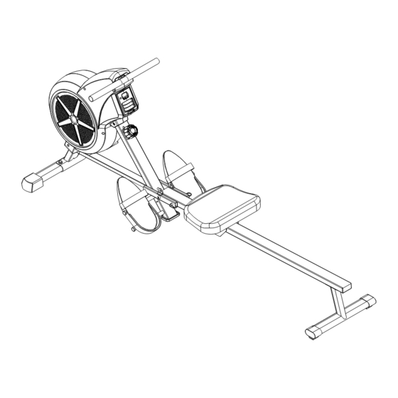
Page 1: Instruction Manual
INSTRUCTION MANUAL IMPORTANT: Please retain the instruction manual for maintenance and adjustment instructions. Search “How to assemble JLL Ventus 1 Air Rower” on Youtube for a step-by-step video guide on how to assemble your rowing machine. -
Page 2: Important Safety Information
6. Always use the equipment as indicated. If you find any defective components while assembling or checking the equipment, or if you hear any unusual noises coming from the equipment during exercise, discontinue use of the equipment immediately. Please contact JLL Fitness on 0800 6123 988 for advice on how to resolve the issue. -
Page 3: Exploded Diagram
EXPLODED DIAGRAM 47 46 14 43 TOOLS PACK CONTENT... -
Page 4: Parts List
PARTS LIST Description Spec. Qty. Description Spec. Qty. Medium Bolt M8*20*S6 Bearing Φ35*d17*16 Washer d8*Φ16*1.5 Belt Wheel Front Stabilizer Bearing 6000-2RS CXSH 4L/R End Cap M10*1*H3*S14 M6*55*15*S10 Screw ST4.2*19*Φ8 Large Bolt Grade 8.8 Fan Wheel Mesh Belt t1.5*22*2150 Fixing Axle for Mesh Inertial Axle Φ10*150 Φ10*40*Φ6.1... - Page 5 Description Spec. Qty. Description Spec. Qty. Rubber Pad 84.5*49.5*9.7 U Shape Baffle End Cap J60*30*15 Seat Support Sensor Wire End Cap Φ28*15 Sleeve Bolt Φ10*95*M6*25 Bolt M8*100*20*S13 Washer d10*Φ20*2 Round Magnet Φ15 *7 Small Bolt M6*16*S5 Sliding Rail Pull Pin Φ10*100*105 Grommet Φ16...
-
Page 6: Assembly Instructions
ASSEMBLY INSTRUCTIONS STEP 1: #1 M8*20*S6 2PCS #52 d8 2PCS Attach the Front Stabilizer (No. 3) to the Main #2 d8* 16*1.5 2PCS Frame (No. 49) using 2 Medium Bolts (No. 1), 2 Spring Washers (No. 52) and 2 Washers (No. - Page 7 STEP 3: #1 M8*20*S6 2PCS #2 d8* 16*1.5 2PCS Slide the Seat (No. 71) onto the Sliding Rail #52 d8 2PCS (No. 79). S6 #B Attach the Rear Stabilizer (No. 81) to the Sliding Rail (No. 79) using 2 Medium Bolts (No.
-
Page 8: Specifications
EXERCISE MONITOR SPECIFICATIONS TIME ………………………………………………………..………………….. 00:00 - 99:59 MIN:SEC COUNT ……………………………………………………………………..….… 0 - 9999 STROKES CALORIE …………………………………………………………………………..…….. 0 - 9999 KCAL REPS/MIN (STROKES/MIN) ……………………………………………….. 0 - 9999 STROKES/MIN OPERATION PROCEDURES MODE: To select the function you want to display, hold the key for 4 seconds to reset all function values (full reset). - Page 9 ADJUSTMENT GUIDE ADJUSTING THE PEDALS The pedal strap length can be adjusted to fit the user’s foot size. To tighten, pull the Velcro end of the pedal strap upward then to the right and down to secure it to the mesh side of the strap. MOVING THE MACHINE To move the machine, lift up the rear stabilizer until the transportation wheels on the front stabilizer touch the ground.
-
Page 10: Adjustment Guide
ADJUSTMENT GUIDE Figure A When not in use, you can save space by folding the Sliding Rail (No. 79). Lift the Sliding Rail (No. 79) where it joins the Main Frame (No. 49). With other hand, remove the Pull Pin (No. 67). -
Page 11: Contact Information
CONTACT INFORMATION 0800 6123 988 contact JLLfitness.co.uk SUPPORT.JLLFITNESS.CO.UK... - Page 12 WWW.JLLFITNESS.COM @JLLFitness...