Samsung MWR-WE10N Installation Manual
Wired remote controller
Hide thumbs
Also See for MWR-WE10N:
- Manual (32 pages) ,
- User manual (32 pages) ,
- Installation manual (24 pages)
Table of Contents
Advertisement
Advertisement
Table of Contents

Related Manuals for Samsung MWR-WE10N


Summary of Contents for Samsung MWR-WE10N
- Page 1 NASA_Wired Remote Control_MWR-WE10N_EN_IM_03716A(1).indd 24 2013-02-01 오후 6:34:12...
-
Page 2: Air Conditioner
Wired remote controller MWR-WE10N Air Conditioner installation manual This manual is made with 100% recycled paper. imagine the possibilities Thank you for purchasing this Samsung product. RU AR DB68-03716A(1) NASA_Wired Remote Control_MWR-WE10N_EN_IM_03716A(1).indd 25 2013-02-01 오후 6:34:13... -
Page 3: Safety Information
Safety Information This installation manual explains how to install a Wired Remote Controller connected to the indoor unit of your Trane system air conditioner. Please read this manual thoroughly before installing the product. (Please refer to appropriate installation for any optional product installation.) WARNING Hazards or unsafe practices that may result in severe personal injury or death. CAUTION Hazards or unsafe practices that may result in minor personal injury or property damage. WARNING Contact a service center for installation. Potential risk of malfunction, water leak, electric shock and fire. Install the product with proper power supply. Potential risk of fire or product damage. Consult the place of purchase or a contact center to disassemble or repair the product. Potential risk of malfunction, electric shock, or fire. - Page 4 CAUTION Do not install the product where there’s combustible gas. Potential risk of fire and explosion. Ensure no water gets into the Wired Remote Controller. Potential risk of electric shock or fire. Install the air conditioner away from direct exposure to sunlight, in room temperature range of 0°C(32°F)~39°C(102°F). Potential risk of electric shock or malfunction. ...
-
Page 5: Wired Remote Controller Installation
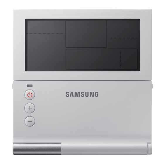
Wired Remote Controller Installation Optional accessories Wired Remote Installation Cable Tie (2) Cable Clamp(3) M4X16 Screw (5) User Manual (1) U Terminal (4) Controller (1) Manual (1) • T he Wired Remote Controller should be installed by an installation expert. • C heck and confirm the power is off before installing your Wired Remote Controller. • I nstall the Wired Remote Controller cables in accordance with the electrical wiring rules, and allow it to pass through the inner area of the wall so that other people can’t reach it. External Dimensions [Unit : mm(inch)] 120.0(4.72) 19.5(0.76) NASA_Wired Remote Control_MWR-WE10N_EN_IM_03716A(1).indd 4 2013-02-01 오후 6:34:06... - Page 6 Wired Remote Controller Installation 1. Push the two hooks at the bottom of your Wired Remote Controller at the same time, and then pull up the front cover to separate it from the rear cover. Push the two hooks at the same time. • I nsert a flat head screwdriver into the square groove in the upper area of the hook to disassemble it easily.
- Page 7 Wired Remote Controller Installation Wired Remote Controller Installation 3. Using more than two screws, firmly affix the rear cover of the remote controller to the wall, and then connect the communication & power cable[(F3,F4) or (3, 4)], making sure these cables have reasonable length, to the terminal at the back of the cover.
-
Page 8: Tracking Your Indoor Unit From The Wired Remote Controller
Tracking Your Indoor Unit from the Wired Remote Controller Indicates tracking in progress Displays the total number of units searched 1. Tracking of your Wired Remote Controller will automatically start when you turn on the power after installation. 2. If you want to perform tracking again after installation, then press the Esc and Delete buttons at the same time for more than five seconds. - Page 9 Wired Remote Controller Installation Individual Control with Your Wired Remote Controller Individual control means that you are using one remote controller to control one indoor unit or ventilator(ERV). When Connected to an Indoor Unit Only Outdoor Unit COM1(F1, F 2) COM1(F1, F 2) Indoor Unit Indoor Unit Indoor Unit COM2(F3, F 4) COM2(F3, F4) COM2(F3, F 4) Wired Remote Wired Remote Wired Remote Controller...
- Page 10 Group Control with Your Wired Remote Controller G roup control means that you are using one Wired Remote Controller to control two or more indoor units and ventilator(ERV) at the same time. When Connected to an Indoor Unit Only (1) U sing One Wired Remote Controller to control three indoor Units Outdoor Unit COM1(F1, F2) COM1(F1, F2) COM1(F1, F2) Indoor Unit Indoor Unit Indoor Unit COM2(F3, F4) COM2(F3, F4) Wired Remote Controller (2) U sing One Wired Remote Controller to control indoor units connected to different outdoor unit Outdoor Unit COM1(F1, F2) Indoor Unit COM2(F3, F4) Outdoor Unit Wired Remote Controller COM1(F1, F2)
- Page 11 Wired Remote Controller Installation When Connected to an ventilator(ERV) Only (1) U sing One Wired Remote Controller to Control Three ventilator(ERV) Master ventilator(ERV) COM1(F1, F2) COM1(F1, F2) COM1(F1, F2) Ventilator(ERV) Ventilator(ERV) Ventilator(ERV) COM2(F3, F4) COM2(F3, F4) Wired Remote Controller • R egardless of the ventilator(ERV)'s group address (RMC address), only the ventilator(ERV) connected to COM2 controlled in group. NASA_Wired Remote Control_MWR-WE10N_EN_IM_03716A(1).indd 10 2013-02-01 오후 6:34:08...
- Page 12 When Connected to an Indoor Unit and an ventilator(ERV) together (1) U sing One Wired Remote Controller to control multiple indoor units and ventilator(ERV) Outdoor Unit COM1(F1, F 2) COM1(F1, F 2) COM1(F1, F 2) Ventilator(ERV) Indoor Unit Indoor Unit Indoor Unit COM2(F3, F 4) COM2(F3, F 4) COM2(F3, F 4) Wired Remote Controller (2) U sing One Wired Remote Controller to control indoor units connected to different outdoor unit and ventilator(ERV) Outdoor Unit COM1(F1, F 2)
- Page 13 Wired Remote Controller Installation Controlling 2-Remote controller 2 -Remote controller is controlling one indoor unit, ventilator(ERV) or one group of indoor units and ventilator(ERV) with two remote controllers. When Connected to an Indoor Unit Only Outdoor Unit COM1(F1, F 2) Indoor Unit COM2(F3, F 4) Wired Remote Wired Remote Controller (Master) Controller (Slave) When Connected to an ventilator(ERV) Only Master ventilator(ERV) COM1(F1, F2) Ventilator(ERV) COM2(F3, F4) Wired Remote Controller Wired Remote Controller (Master)
- Page 14 When Connected to an Indoor Unit and an ventilator(ERV) Together Outdoor Unit COM1(F1, F 2) Indoor Unit COM2(F3, F 4) COM2(F3, F 4) Ventilator(ERV) Wired Remote Wired Remote Controller (Master) Controller (Slave) • R egardless of the indoor unit group address (RMC address), only the indoor units connected to COM2 are controlled by 2-remote controller. • F or the slave Wired Remote Controller settings, please refer to the sections about the additional functions of the Wired Remote Controller. (Refer to page20) 0 : Master, 1 : Slave NASA_Wired Remote Control_MWR-WE10N_EN_IM_03716A(1).indd 13 2013-02-01 오후...
- Page 15 Wired Remote Controller Installation Initializing Your Wired Remote Controller Communication I f the number of indoor unit or ventilator(ERV) is decreased while you are using your remote control to control one indoor unit, ventilator(ERV) or a group of indoor units and ventilator(ERV), then you need to initialize your remote controller communication. 1. Press the Esc and Delete buttons at the same time for more than five seconds. Y our Wired Remote Controller will be initialized, and the device will search for the indoor units/ventilator(ERV) connected to your Wired Remote Controller again. NASA_Wired Remote Control_MWR-WE10N_EN_IM_03716A(1).indd 14 2013-02-01 오후 6:34:10...
- Page 16 Errors Displayed on Your Wired Remote Controller E rror codes for the Wired Remote Controller and the product connected to your Wired Remote Controller will be displayed in the LCD display. LCD Display When an Error Occurs in Your Indoor/Outdoor Units (Product Group Display: A) T he product address for the error will be displayed, followed by the error code. Example : Error 101 occurs for Indoor Unit No. 200012. Indoor Unit When an Error Occurs in Your Ventilator(ERV) (Product Group Display: B) T he product address for the error will be displayed, followed by the error code.
-
Page 17: Wired Remote Controller Error Codes
Wired Remote Controller Installation Wired Remote Controller Error Codes Display Description Communication error between wired remote controller and indoor/ERV units after successful communication. No communication between Master(Main) and Slave(Sub) wired remote controllers. No communication between wired remote controller and indoor/ERV units Over 16 indoor/ERV indoor units installed. Two or more wired remote controllers set as Slave(SUB). Temperature sensor Open/Short error. EEPROM Read, Write error • F or the error codes for your indoor/outdoor units and ventilator(ERV), refer to the installation manual of each device. [Setting/Cancelling the Mode master indoor unit] • M ode master indoor unit setting is simply selecting an indoor unit that will become standard among many indoor units to prevent mixed operation (which one or more indoor units operating in different operation mode). - S etting: Connect just 1 indoor unit and stop the operation. Then press and hold the Mode button for 5 seconds to set the indoor unit as 'Mode master indoor unit' - C ancelling: Connect just 1 indoor unit and stop the operation. Then press and hold the Fan speed button for 5 seconds to cancel the 'Mode master indoor unit' setting. -
Page 18: Wired Remote Controller Installation/Service Mode
Wired Remote Controller Installation/Service Mode Additional Functions of Your Wired Remote Controller Data bit Main Menu Sub-menu 1 2 3 NASA_Wired Remote Control_MWR-WE10N_EN_IM_03716A(1).indd 17 2013-02-01 오후 6:34:11... - Page 19 Wired Remote Controller Installation/Service Mode 1. If you want to use the various additional functions for your Wired Remote Controller, press the Set and Esc buttons at the same time for more than three seconds. You will enter the additional function settings, and the [main menu] will be displayed. 2. Refer to the list of additional functions for your Wired Remote Controller on the next page, and select the desired menu.
- Page 20 Additional Functions of Your Wired Remote Controller • ‘ NONE’ will be displayed if the indoor unit does not support the function. In some cases, the setting may not possible or it may be not applied though it is set on the unit. • I f communication initialization is needed after the setting, the system will reset automatically and communication will be initialized. Main Data Factory Function Description Unit menu menu setting 0 – Cooling/Heating, Cooling/Heating selection 1 – Cooling only Use of wireless remote controller 0 – No use, 1 - Use Wireless remote controller Option setting/checking (1) MAIN/SUB wired remote 0 –MAIN, 1- SUB controller Temperature unit 0 – Celcius(°C), 1 – Fahrenheit(°F) 0 – Indoor unit, Temperature sensor selection...
- Page 21 Wired Remote Controller Installation/Service Mode Main Data Factory Function Description Unit menu menu setting Indoor unit room temperature 1,2,3 Room temperature °C Indoor unit EVA IN temperature 1,2,3 EVA IN temperature °C Indoor unit EVA OUT temperature 1,2,3 EVA OUT temperature °C Indoor unit EEV step 1,2,3 EEV step Use of central control 0 – No use, 1 - Use Use of drain pump 0 – No use, 1 - Use Indoor unit option checking (1) Use of electric heater 0 – No use, 1 - Use Use of hot water coil 0 – No use, 1 - Use Use of external control 0 – No use, 1 - Use Use of RPM compensation 0 – No use, 1 - Use Filter time...
- Page 22 Main Data Factory Function Description Unit menu menu setting Indoor unit Master setting/ 123456 address checking Master setting/checking (F3F4 line Indoor unit master) ERV unit Master setting/ 123456 address checking Mode master indoor unit Mode master indoor unit 123456 address checking setting/checking (F1F2 line Indoor unit master) 3)* Mode master indoor unit setting 0-No use, 1-Use, 2-Release Factory setting 0-No use, 1-Reset Power Master Reset 4)* Reset 0-No use, 1-Reset Addressing Reset 0-No use, 1-Reset 1)* T he total option codes are 24 digits. You can set six digits at a time and it is distinguished by page number. Press [>] button to go to the next page.
- Page 23 Wired Remote Controller Installation/Service Mode The example of Wired Remote Controller option setting method 1. Press Set and ESC buttons at the same time for more than 3 seconds. ( Main menu) will be displayed and then press the [∧]/[∨] button to select no.1. 2. Press [>] button to select the number you will set. P ress [∧]/[∨] button and select no.1 ...
- Page 24 Memo NASA_Wired Remote Control_MWR-WE10N_EN_IM_03716A(1).indd 23 2013-02-01 오후 6:34:12...