Table of Contents
Advertisement
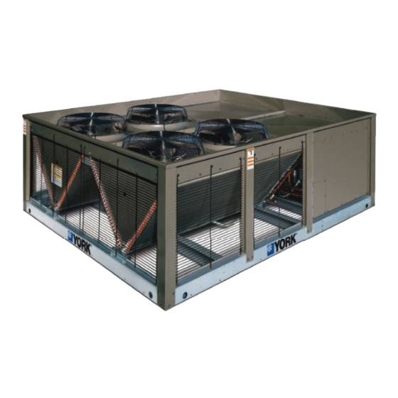
R-410A
MODELS:
YD360 Thru 600
30 - 50 Ton
60 Hertz
Nomenclature . . . . . . . . . . . . . . . . . . . . . . . . . . . . . . . . . . . . . 2
General . . . . . . . . . . . . . . . . . . . . . . . . . . . . . . . . . . . . . . . . . . 2
Renewal Parts . . . . . . . . . . . . . . . . . . . . . . . . . . . . . . . . . . . . . 3
Agency Approvals . . . . . . . . . . . . . . . . . . . . . . . . . . . . . . . . . . 3
Inspection . . . . . . . . . . . . . . . . . . . . . . . . . . . . . . . . . . . . . . . . 3
Physical Data . . . . . . . . . . . . . . . . . . . . . . . . . . . . . . . . . . . 4
Installation . . . . . . . . . . . . . . . . . . . . . . . . . . . . . . . . . . . . . . . . 5
Limitations . . . . . . . . . . . . . . . . . . . . . . . . . . . . . . . . . . . . . . 5
Location. . . . . . . . . . . . . . . . . . . . . . . . . . . . . . . . . . . . . . . . 5
Clearances . . . . . . . . . . . . . . . . . . . . . . . . . . . . . . . . . . . . . 7
Rigging . . . . . . . . . . . . . . . . . . . . . . . . . . . . . . . . . . . . . . . . 7
Phasing . . . . . . . . . . . . . . . . . . . . . . . . . . . . . . . . . . . . . . . . 8
Electrical Data . . . . . . . . . . . . . . . . . . . . . . . . . . . . . . . . . . . 9
1 YD360 thru 600 Physical Data . . . . . . . . . . . . . . . . . . . . . 4
2 Unit Application Data . . . . . . . . . . . . . . . . . . . . . . . . . . . . 5
3 Corner Weight & Center Of Gravity (Inches) . . . . . . . . . . 6
4 Minimum Clearances . . . . . . . . . . . . . . . . . . . . . . . . . . . . 7
5 Electrical Data - Outdoor Unit . . . . . . . . . . . . . . . . . . . . . 9
1 Corner Weights & Center Of Gravity . . . . . . . . . . . . . . . . 6
2 Typical Rigging . . . . . . . . . . . . . . . . . . . . . . . . . . . . . . . . 7
Matched with YD360/480/600 Condenser . . . . . . . . . . . 12
4 Typical ND360/480 & M1CZ600A Liquid Line Solenoid
Wiring . . . . . . . . . . . . . . . . . . . . . . . . . . . . . . . . . . . . . . . 12
5 Typical Liquid Line Solenoid Wiring . . . . . . . . . . . . . . . . 13
6 YD Unit Dimensions . . . . . . . . . . . . . . . . . . . . . . . . . . . . 14
7 30 Ton Power And Control Wiring Connections . . . . . . 15
9 30 Ton Piping Connections . . . . . . . . . . . . . . . . . . . . . . 16
TABLE OF CONTENTS
Refrigerant Mains . . . . . . . . . . . . . . . . . . . . . . . . . . . . . . . 10
Piping And Electrical Connection Sizes . . . . . . . . . . . . . . 16
Piping And Electrical Connections . . . . . . . . . . . . . . . . . . 17
Start-Up . . . . . . . . . . . . . . . . . . . . . . . . . . . . . . . . . . . . . . . . . 17
Crankcase Heater . . . . . . . . . . . . . . . . . . . . . . . . . . . . . . . 17
Operation . . . . . . . . . . . . . . . . . . . . . . . . . . . . . . . . . . . . . . . 18
Sequence of Operation . . . . . . . . . . . . . . . . . . . . . . . . . . . 18
Troubleshooting . . . . . . . . . . . . . . . . . . . . . . . . . . . . . . . . . . 20
Board Navigation Examples:. . . . . . . . . . . . . . . . . . . . . . . 21
Typical Wiring Diagrams . . . . . . . . . . . . . . . . . . . . . . . . . . 31
Start-Up Sheet . . . . . . . . . . . . . . . . . . . . . . . . . . . . . . . . . . . 33
LIST OF TABLES
6 Unit Dimensions (Inches) . . . . . . . . . . . . . . . . . . . . . . . . 14
(Inches) . . . . . . . . . . . . . . . . . . . . . . . . . . . . . . . . . . . . . 16
8 Electrical Power Knockout Sizes (Inches) . . . . . . . . . . . 16
9 Smart Equipment™ UCB Details . . . . . . . . . . . . . . . . . . 23
LIST OF FIGURES
10
40 & 50 Ton Piping Connections . . . . . . . . . . . . . . . . . 17
11 Fan Orientation Control Box End . . . . . . . . . . . . . . . . . . 19
12 Compressor Location . . . . . . . . . . . . . . . . . . . . . . . . . . . 20
13 Unit Control Board . . . . . . . . . . . . . . . . . . . . . . . . . . . . . 23
14 YD360 Charging Curves . . . . . . . . . . . . . . . . . . . . . . . . 29
15 YD480 Charging Curves . . . . . . . . . . . . . . . . . . . . . . . . 29
16 YD600 Charging Curves . . . . . . . . . . . . . . . . . . . . . . . . 30
17 Typical 208/230 Volt, YD360/480/600 Condensing Unit
Wiring Diagram . . . . . . . . . . . . . . . . . . . . . . . . . . . . . . . 31
18 Typical 460/575 Volt, YD360/480/600 Condensing Unit
Wiring Diagram . . . . . . . . . . . . . . . . . . . . . . . . . . . . . . . 32
5012886-YIM-B-0517
Advertisement
Table of Contents

Related Manuals for York YD480 Series


Summary of Contents for York YD480 Series
-
Page 1: Table Of Contents
R-410A MODELS: YD360 Thru 600 30 - 50 Ton 60 Hertz TABLE OF CONTENTS Nomenclature ........2 Refrigerant Mains . -
Page 2: Nomenclature
5012886-YIM-B-0517 Nomenclature Configured Split Condenser Model Number Nomenclature Y D 360 C00 A 2 A AA 2 A Product Style A = Style A Product Category Y = Split System, Condenser, AC, R-410A Product Generation 2 = Second Generation Product Identifier D = Standard Efficiency, 4-Pipe, R-410A Product Options AA = None... -
Page 3: Renewal Parts
5012886-YIM-B-0517 Safety Considerations Reference Installer should pay particular attention to the words: NOTE, This instruction covers the installation and operation of the CAUTION, and WARNING. Notes are intended to clarify or basic condensing unit. For refrigerant piping installation make the installation easier. Cautions are given to prevent instructions refer to document 247077 “Application Data - equipment damage. -
Page 4: Physical Data
5012886-YIM-B-0517 Physical Data Table 1: YD360 thru 600 Physical Data Models Component YD360 YD480 YD600 Nominal Tonnage REFRIGERANT Refrigerant type R-410A R-410A R-410A Holding charge (lb) System #1 47.0 51.0 Operating Charge (lb) System #2 47.0 51.0 DIMENSIONS (inches) Length 128.5 128.5 128.5... -
Page 5: Installation
5012886-YIM-B-0517 The condensing unit and the evaporator should be Table 2: Unit Application Data positioned to minimize the number of bends in the 208/230-3-60 187/252 refrigerant piping. Voltage Variation 460-3-60 432/504 The condensing unit should be as close to the evaporator Min. -
Page 6: Corner Weight & Center Of Gravity (Inches)
5012886-YIM-B-0517 Corner Weight & Center Of Gravity (Inches) Table 3: Unit Dimensions Unit Weight (Lbs.) Weight Weight (Inches) Unit Model Dim X Dim Y A to B D to C Shipping Operation Length Width YD360 1875 1895 128.5 88.5 55.2 44.1 YD480 2315... -
Page 7: Clearances
5012886-YIM-B-0517 Clearances The unit must be installed with sufficient clearance for air to enter the condenser coil, for air discharge and for servicing access. See Table 4 for clearances. NOTE: Additional clearance is required to remove the Before lifting a unit, make sure that its weight is compressors out the back of the unit, unless a means is distributed equally on the cables so that it will lift evenly. -
Page 8: Phasing
5012886-YIM-B-0517 POE (polyolester) compressor lubricants are known to cause Power Wiring long term damage to some synthetic roofing materials. Check the available power and the unit nameplate for correct voltage. Run the necessary number of properly sized wires to the unit. Provide a disconnect switch (if not included with the unit) and fusing as required. -
Page 9: Electrical Data
5012886-YIM-B-0517 Electrical Data Table 5: Electrical Data - Outdoor Unit Compressors Outdoor Fan Motor Minimum Maximum Model Circuit Fuse Size Power Power Ampacity Supply (each) (each) (each) Supply (each) 208/230-3-60 25.0 208/230-3-60 1 1/2 129.5 YD360 460-3-60 12.2 460-3-60 1 1/2 63.5 575-3-60 575-3-60... -
Page 10: Refrigerant Mains
5012886-YIM-B-0517 Refrigerant Mains Take Adequate Precautions Many service problems can be avoided by taking adequate precautions to provide an internally clean and dry system and This Split-System (Air Condensing / Air Handling) unit is by using procedures and materials that conform to established one component of an entire system. - Page 11 5012886-YIM-B-0517 cooled. The flow of nitrogen will prevent oxidation of the sealing disks and prepare the joints for connections of the main copper lines during installation. lines. Always punch a small hole in sealing disks before unbrazing to Connect the main liquid line to the liquid line connection on the prevent the pressure in the line from blowing them off.
-
Page 12: Typical Field Wiring Diagram Nd360/480 Evaporator Units, Nd600 Air Handler And M1Cz600A Evaporator Coil When Matched With Yd360/480/600 Condenser
5012886-YIM-B-0517 CONDENSER CONTROL BOX SE CONTROL BOARD THERMOSTAT CONNECTIONS UCB 2 W1 W2 Y1 G Y2 0CC R SD-24 SYSTEM 2 C S1 S2 G1 G2 S3 S4 UCB 1 W1 W2 Y1 G Y2 0CC R SD-24 SYSTEM 1 C S1 S2 G1 G2 S3 S4 LIQUID LINE THERMOSTAT... -
Page 13: Typical Liquid Line Solenoid Wiring
5012886-YIM-B-0517 Standard Terminal Block on ND360/480 and ND600 with M1CZ600A models. On non ND models isolation relays must be installed to avoid overloading on 75 VA transformer on condensing unit. Primary side of transformer connect to line side of power supply. -
Page 14: Yd Unit Dimensions
5012886-YIM-B-0517 REAR LEFT RIGHT FRONT Figure 6: YD Unit Dimensions Table 6: Unit Dimensions (Inches MODEL YD360 128.5 88.5 37.5 41.8 40.0 46.1 37.1 23.6 YD480 128.5 88.5 57.7 41.8 40.0 46.1 37.1 23.6 YD600 128.5 88.5 57.7 41.8 40.0 46.1 37.1 23.6... -
Page 15: 30 Ton Power And Control Wiring Connections
5012886-YIM-B-0517 Control Wiring Power Wiring 37.518 12.878 9.628 SEE DETAIL RIGGING HOLES 19.358 2.313 20.858 2.750 5.183 2.500 22.358 DETAIL RIGGING HOLES SCALE 0.250 88.140 Figure 7: Ton Power And Control Wiring Connections Control Wiring Power Wiring 57.689 33.049 29.799 19.358 20.858 22.358... -
Page 16: 30 Ton Piping Connections
5012886-YIM-B-0517 Piping And Electrical Connection Sizes Table 7: Piping And Electrical Connection Sizes (30/40/50T) (Inches) CONNECTION ENTRY SIZE SUCTION LINE SYS #1 1-5/8 OD LIQUID LINE SYS #1 7/8 OD SUCTION LINE SYS #2 1-5/8 OD LIQUID LINE SYS #2 7/8 OD POWER WIRING KNOCKOUT SEE TABLE 8... -
Page 17: Piping And Electrical Connections
5012886-YIM-B-0517 57.689 11.385 10.974 37.731 Liquid (Sys 2) 41.934 Suction (Sys 2) 46.206 Suction (Sys 1) 50.409 Liquid (Sys 1) 88.140 Figure 10: 40 & 50 Ton Piping Connections Piping And Electrical Connections Pre-Start Check Before starting the unit, complete the following check list: Piping connections are made from the rear of units. -
Page 18: Operation
5012886-YIM-B-0517 Move the system switch on the thermostat to the AUTO or pressure switch opens, the Smart Equipment™ control COOL position. board will monitor the low-pressure switch to make sure it closes within one minute. If it fails to close, the unit will Reduce the setting of the room thermostat to energize the shut down the associated compressor and begin an compressor. -
Page 19: Fan Orientation Control Box End
5012886-YIM-B-0517 voltage. Refer to the wiring labels inside of the unit Compressor 4 and the RY4 (Staging Relay) for 4LLS (Solenoid) control access panel for additional information. and both condenser fans FM3 & FM4 of System 2. Once the thermostat has been satisfied, the SE control boards Continuous Blower will de-energize Y1, Y2, Y3 and Y4. -
Page 20: Smart Equipment™ Control Board Navigation Components
5012886-YIM-B-0517 Terminals Y1 and Y2 of the Smart Equipment™ control Normal Maintenance board (UCB 2) controlling System 2, should be connected to stages 3 and 4 of the 4 stage thermostat. Prior to any of the following maintenance procedures, shut off all power to the unit, to avoid personal injury. Periodic maintenance consists of changing or cleaning filters COMPRESSOR #2 and general cleaning of the outdoor coil. -
Page 21: Smart Equipment™ Firmware Version 3.2 Basic Unit Control Board Navigation Examples
5012886-YIM-B-0517 SMART EQUIPMENT™ FIRMWARE VERSION 3.2 BASIC UNIT CONTROL BOARD NAVIGATION EXAMPLES: The following document details the navigation and viewing of navigate the basic status menu and how to change basic the LCD display screen equipped as a standard item on the configuration settings. - Page 22 5012886-YIM-B-0517 When the "Cancel" button is pressed multiple times to exit each menu level and the screen returns to the first "Status, Alarms" dis- play the next demonstration can begin. In this demonstration the information below steps through the "Commissioning" menu. Step 2- Once commission Step 1- Beginning at the status/alarm screen toggle the joystick down three times.
-
Page 23: Smart Equipment™ Ucb Details
5012886-YIM-B-0517 THERMOSTAT WIRED HERE SD-24 Figure 13: Unit Control Board Table 9: Smart Equipment™ UCB Details Description Function & Comments Terminal Directional orientation: viewed with silkscreen labels upright Limit, 24 VAC power and shutdown connections from unit wiring harness at left on upper edge of UCB Monitored 24 VAC input through heat section limit If voltage is absent, indicating the heat section is over- LIMIT... - Page 24 5012886-YIM-B-0517 Table 9: Smart Equipment™ UCB Details (Continued) Description Function & Comments Connects through circuit trace to the thermostat connection 24 VAC hot for switched inputs to the UCB strip R terminal, right FAN OVR pin, right HPS1 pin, right HPS2 pin, lower DFS pin and lower APS pin Terminal Thermostat connection strip on left edge of UCB 1st stage heating request, 24 VAC input switched...
- Page 25 5012886-YIM-B-0517 Table 9: Smart Equipment™ UCB Details (Continued) Description Function & Comments Pin Temperature sensor connections at right on upper edge of UCB Input required for operation; 3.625 VDC reading SAT+ to SAT– Supply Air Temperature sensor input from 10KΩ with open circuit.
- Page 26 5012886-YIM-B-0517 Table 9: Smart Equipment™ UCB Details (Continued) Description Function & Comments Output is active with indoor blower operation. For CV units: this output provides stepped IntelliSpeed control of the indoor 2-10 VDC (0-100%) output for the indoor blower blower VFD based on fan-only, cooling stage and heating stage Variable Frequency Drive outputs.
- Page 27 5012886-YIM-B-0517 Table 9: Smart Equipment™ UCB Details (Continued) Description Function & Comments Input is only considered after 30 seconds of C1 output; 24 VAC hot return from refrigerant circuit 1 Low afterwards, input must be present to allow C1 output. Three LPS1 (left pin) Pressure Switch...
- Page 28 5012886-YIM-B-0517 Table 9: Smart Equipment™ UCB Details (Continued) Description Function & Comments Button for display menu acknowledgment and ENTER navigation Button for display menu navigation and zeroing of CANCEL active compressor ASCD timer 4-way Joystick for display menu navigation Item USB connector at right of UCB Used for backup, restoration, &...
-
Page 29: Yd360 Charging Curves
5012886-YIM-B-0517 Charging Curves 30 Ton 115º 105º 95º 85º 65º Suction Pressure (psi) 1. Make sure that all condenser fans are running when charging. 2. This chart is applicable to unit with the TXV's left to the factory setting. If the TXV's have been adjusted in the field, the charging chart may no longer apply. -
Page 30: Yd600 Charging Curves
5012886-YIM-B-0517 Charging Curves 50 Ton 115º 105º 95º 85º 65º Suction Pressure (psi) 1. Make sure that all condenser fans are running when charging. 2. This chart is applicable to unit with the TXV's left to the factory setting. If the TXV's have been adjusted in the field, the charging chart may no longer apply. -
Page 31: Typical Wiring Diagrams
5012886-YIM-B-0517 Typical Wiring Diagrams Figure 17: Typical 208/230 Volt, YD360/480/600 Condensing Unit Wiring Diagram Johnson Controls Unitary Products... -
Page 32: Wiring Diagram
5012886-YIM-B-0517 Typical Wiring Diagrams Figure 18: Typical 460/575 Volt, YD360/480/600 Condensing Unit Wiring Diagram Johnson Controls Unitary Products... -
Page 33: Start-Up Sheet
Technical Services Department available. Therefore, some variation in the startup procedure will 5005 York Drive exist depending upon the products capacity, control system, Norman, OK 73069 options and accessories installed. - Page 34 5012886-YIM-B-0517 1034350-UCL-D-0817 SAFETY WARNINGS The inspections and recording of data outlined in this procedure are required for start-up of Johnson Controls/UPG's packaged Lethal voltages are present during some start-up products. Industry recognized safety standards and practices checks. Extreme caution must be used at all times. must be observed at all times.
- Page 35 5012886-YIM-B-0517 1034350-UCL-D-0817 REFERENCE General Inspection Completed See Notes Unit inspected for shipping, storage, or rigging damage Unit installed with proper clearances Unit installed within slope limitations Refrigeration system checked for gross leaks (presence of oil) Terminal screws and wiring connections checked for tightness Filters installed correctly and clean Condensate drain trapped properly, refer to Installation Manual All field wiring (power and control) complete...
- Page 36 5012886-YIM-B-0517 1034350-UCL-D-0817 Operating Measurements - Air Flow Fan operates with proper rotation (All VFD equipped units with the optional Manual Bypass must be phased for correct blower rotation with the Bypass switch set in the LINE position) ID Fans Exh. Fans Cond.
- Page 37 5012886-YIM-B-0517 1034350-UCL-D-0817 OPERATING MEASUREMENTS - COOLING Liquid Line Discharge Discharge Pressure At Liquid Line Suction Suction Stage Subcooling Superheat Pressure Temp. Service Temp. Pressure Temp. Valve First ° ° ° ° ° Second (if equipped) ° ° ° ° ° Third (if equipped) °...
- Page 38 ________________________________________________________________________________________________________ ________________________________________________________________________________________________________ ________________________________________________________________________________________________________ ________________________________________________________________________________________________________ ________________________________________________________________________________________________________ ________________________________________________________________________________________________________ ________________________________________________________________________________________________________ ________________________________________________________________________________________________________ ________________________________________________________________________________________________________ ________________________________________________________________________________________________________ Subject to change without notice. Printed in U.S.A. 5012886-YIM-B-0517 Copyright © 2017 by Johnson Controls, Inc. All rights reserved. Supersedes: 5012886-YIM-A-0215 York International Corporation 5005 York Drive Norman, OK 73069...