Table of Contents
Advertisement
Instruction Manual and Replacement Parts List
Junior II
High Pressure Air Compressor Unit
Junior II WT
April 26, 2007
BAUER Compressors, Inc.
1328 Azalea Garden Road
Norfolk, Virginia 23502-1944
1st ed. Rev 0 Chg 3
© 2007 Bauer Compressors, Inc.
BAUER
COMPRESSORS
MNL-0391
Phone: (757) 855-6006
Fax: (757) 855-6224
www.bauercomp.com
Advertisement
Table of Contents
Troubleshooting

Related Manuals for Bauer Compressors Junior II WT


Summary of Contents for Bauer Compressors Junior II WT
- Page 1 Junior II High Pressure Air Compressor Unit Junior II WT April 26, 2007 1st ed. Rev 0 Chg 3 MNL-0391 © 2007 Bauer Compressors, Inc. BAUER Compressors, Inc. Phone: (757) 855-6006 1328 Azalea Garden Road Fax: (757) 855-6224 Norfolk, Virginia 23502-1944...
- Page 2 Junior II WT COMPRESSORS This information is believed to be accurate by Bauer Compressors, Inc., as of it’s date of publication, but Bauer offers NO WARRANTY regarding the accuracy, or continuing accuracy, of the information set forth herein. Bauer shall not be liable for inaccuracies in, or consequences resulting from, your use of this information.
-
Page 3: Table Of Contents
HOW TO USE THE REPLACEMENT PARTS LIST ....................2 HOW TO USE THE APPENDIX............................3 DESIGN ....................................4 AIR FLOW DIAGRAM ..............................5 1.5.1 Junior II WT ..................................6 1.5.2 Compressor Block Technical Specifications........................6 1.5.3 Compressor Drive Technical Specifications ........................6 CHAPTER 2: - - - - - - - - - - - - - - - - - - - - - - - OPERATION PREPARATION FOR OPERATION.......................... - Page 4 BAUER Junior II WT COMPRESSORS 3.4.2.1 Electric Motor ................................18 3.4.2.2 Gasoline Engine ................................18 3.4.2.3 Compressor Block.................................18 REPLACEMENT PARTS LIST ............................20 CHAPTER 4:- - - - - - - - - - - - - - - - - - - JRII MAINTENANCE MAINTENANCE RECORD.............................33...
- Page 5 BAUER MNL-0391 COMPRESSORS COOLING SYSTEM................................. 53 6.4.1 General ..................................... 53 CHAPTER 7: - - - - - - - - - - - - - - - - - - - - - - - - APPENDIX SAFETY....................................54 7.1.1 General Safety Precautions ..............................
- Page 6 IGURES CHAPTER 1:- - - - - - - - - - - - - - - - - - - - - INTRODUCTION Figure 1-1 Junior II WT ................................4 Figure 1-2 Internal Air Flow Diagram ............................5 CHAPTER 2:- - - - - - - - - - - - - - - - - - - - - - - OPERATION Figure 2-1 Air Storage Bottle Valve Operating Sequence ......................8...
-
Page 7: How To Use This Manual
INTRODUCTION 1.1 How To Use This Manual This manual contains the operating and maintenance instructions for the Bauer Compressors, Inc. prod- uct(s) listed on the front cover. All instructions in this manual should be observed and carried out as written to prevent damage or pre- mature wear to the product or the equipment served by it. -
Page 8: How To Use The Replacement Parts List
BAUER JUNIOR II WT COMPRESSORS 1.2 How to Use the Replacement Parts List • A lozenge ◊ in the Item Number column indicates the part number for a complete assembly. • A dagger (†) in the Qty column with or without an ellipsis (…) in the Part Number column means the part is illustrated for assembly purposes only and is not available for sale as an individual component. -
Page 9: How To Use The Appendix
BAUER MNL-0391 COMPRESSORS 1.3 How to Use the Appendix Information contained in the Appendix to this manual includes the following. • The safety instructions applicable to this product. They must be read, understood and complied with prior to operating the product. •... -
Page 10: Design
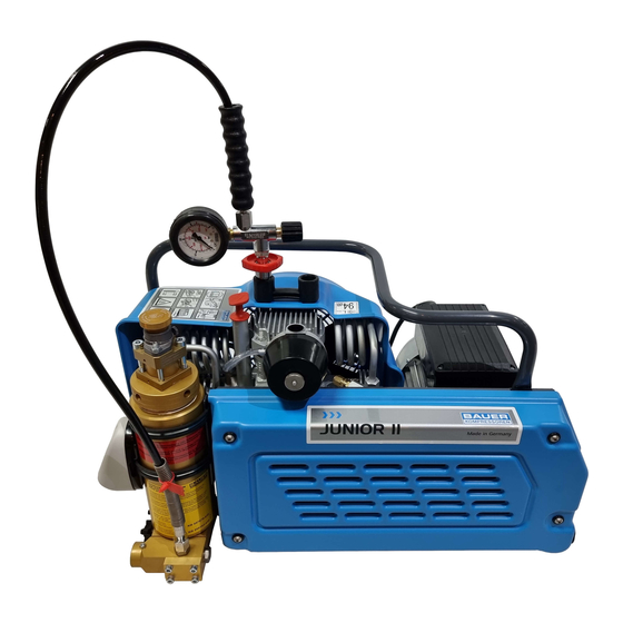
BAUER Junior II WT COMPRESSORS 1.4 Design The Junior II WT compressor units consists of the following major assemblies. • Compressor Block • Electric Motor Drive • P0 Purification System • Fill Hose Assembly • Base Plate and Frame Figure 1-1 Junior II WT 1. -
Page 11: Air Flow Diagram
BAUER MNL-0391 COMPRESSORS 1.5 Air Flow Diagram See Figure 1-4. The air is drawn in through the Telescopic Tube (1) through the Intake Filter (2) and is compressed to final pressure in the Cylinders (3, 4 and 5). It is recooled by the Intercoolers (6 and 7) and the After- cooler (9). -
Page 12: Junior Ii Wt
BAUER Junior II WT COMPRESSORS 1.5.1 Junior II WT Medium Intake Pressure Atmospheric Delivery 1.0 SCFM (100l/min.) Maximum Operating Pressure 5,000 psi (350 bar) Final Safety Valve Pressure Setting As selected Sound Pressure 80dB(A) Sound (immersion) Power 100dB(A) Weight Approximately 100 lbs (44-47 kg) 1.5.2 Compressor Block Technical Specifications... -
Page 13: Chapter 2
BAUER MNL-0391 COMPRESSORS CHAPTER 2: OPERATION 2.1 Preparation for Operation Prior to operating the unit for the first time, read this Instruction Manual carefully. 1. Make sure that all persons operating the compressor unit and associated equipment are familiar with the function of all controls and indicators. -
Page 14: General Procedures
BAUER Junior II WT COMPRESSORS 2.3.1 General Procedures 1. The fill valve connection is of the manual type permitting connection to the air tank without tools. An O-ring is provided for sealing purposes. 2. Compressed air tank fill valves for pressure in excess of 2900 psi (200 bar) are standardized and connectors for 2900 psi (200 bar) and 4400 psi (300 bar) are different and can not be mixed up. -
Page 15: Connecting To The Air Storage Bottle
BAUER MNL-0391 COMPRESSORS 2.3.3 Connecting to the Air Storage Bottle 1. Ensure both the fill valve and bottle valve are closed 2. Connect the air bottle to the compressor fill hose utilizing the fill yoke. 2.3.4 Filling the Bottle 1. First open fill valve. (1) 2. -
Page 16: Lubrication
BAUER Junior II WT COMPRESSORS CHAPTER 3: JUNIOR II COMPRESSOR 3.1 Lubrication 3.1.1 Oil Level Check Check the oil level prior to putting compressor into operation each day 1. Remove dipstick and wipe dry. 2. Reinsert the dipstick ensuring that it is completely seated. -
Page 17: Oil Changes
BAUER MNL-0391 COMPRESSORS 3.1.3 Oil Changes The oil must be changed every 2,000 operating hours or every two years whichever is reached first. 3.1.3.1 Oil Change Procedures 1. Run the compressor until it reaches normal operating temperature. 2. Remove the oil dipstick from oil filler tube. 3. -
Page 18: Telescope Intake Tube
BAUER Junior II WT COMPRESSORS 6. Reinsert filter cartridge, turning it 90° so the mark made in step 2. is at the 3 o’clock position. 7. Inspect O-ring (4) and replace if damaged. 8. Replace plastic cap and tighten knurled nut 3.2.3 Telescope Intake Tube... -
Page 19: Maintenance
BAUER MNL-0391 COMPRESSORS 3.2.5 Maintenance The Intermediate Separator P/N 081798 requires no maintenance. 3.3 Compressor Valves 3.3.1 Description The valve heads of the individual stages form the top part of the cylinders. The intake and pressure valves are fitted inside the valve heads. (Note that the valves are operated by air flow. (See Figure 3-4). On the suction stroke, the intake valve is opened and air flows into the cylinder. -
Page 20: Changing The 1St Stage Valves
BAUER Junior II WT COMPRESSORS • Thirty minutes after restarting the compressor unit, stop the unit, let it cool to ambient temperature and retighten the valve studs and cap nuts. Otherwise valves could work loose due to the setting of the gaskets. -
Page 21: Changing The 2Nd Stage Valves
BAUER MNL-0391 COMPRESSORS Figure 3-7 2nd Stage Valve Head 1. Nut 5. Valve Head 2. Washer 6. O-rings 3. Valve Cover Plate 7. Intake Valve 4. Stud 8. Pressure Valve 3.3.5 Changing the 2nd Stage Valves Both the intake and pressure valves can be serviced from the top of the head. See Figure 3-7. 1. -
Page 22: Changing The 3Rd Stage Valves
BAUER Junior II WT COMPRESSORS 3.3.6 Changing the 3rd Stage Valves On this valve head, the valves are arranged on the upper and lower side due to the small diameter of the 3rd Stage head. See Figure 3-8. Figure 3-8 3rd Stage Valve Head 1. -
Page 23: Repair And Troubleshooting
BAUER MNL-0391 COMPRESSORS 4. Remove Allen screws (7) and take off valve head cover (6). 5. To lift pressure valve out of valve head put two flat head screwdrivers into grooves of the pressure valve body. See Figure 3-9. If necessary turn valve to loosen it, using a 13mm open end wrench on the flat surfaces of the valve. -
Page 24: Troubleshooting Tables
BAUER Junior II WT COMPRESSORS 3.4.2 Troubleshooting Tables 3.4.2.1 Electric Motor TROUBLE CAUSE REMEDY Check all fuses, terminal connec- tions, wire leads, make sure that Motor will not start Electric circuitry faulty motor data complies with mains supply. Motor runs eccentrically... - Page 25 BAUER MNL-0391 COMPRESSORS Intake filter soiled Clean or replace filter cartridge. Pipe coupling leaking Retighten couplings. Air delivery drops Excessive wear of the 3rd stage Replace piston and sleeve of 3rd piston stage. Intermediate pressure too high because of defective inlet or Check and replace inlet or pres- Intermediate pressure safety pressure valve of the following...
-
Page 26: Replacement Parts List
BAUER Junior II WT COMPRESSORS 3.5 Replacement Parts List Figure 3-10 Crankcase, Driving Gear and Fanwheel 29 30 # KIT Qty Part No. Description Notes … 067035 Driving Gear Assembly Items 2 through 7 … N109 Allen Screw … N2862 Washer …... - Page 27 BAUER MNL-0391 COMPRESSORS Figure 3-10 (cont.) Crankcase, Driving Gear and Fanwheel # KIT Qty Part No. Description Notes 12 … N2861 Shaft Seal 13 … 13920 14 … 067013 Dip-stick 15 … N3951 O-ring 16 … 67007 Oil Filler 17 … N1055 Hose 18 …...
-
Page 28: Figure 3-11 Pistons And Cylinders
BAUER Junior II WT COMPRESSORS Figure 3-11 Pistons and Cylinders # KIT Qty Part No. Description Notes … 76548 Cylinder 1st Stage 60mm N4948 O-ring … 069918 1st Stage Piston Assembly … 61354 Cylinder 2nd Stage 28mm N3157 O-ring …... - Page 29 BAUER MNL-0391 COMPRESSORS Figure 3-11 (cont.) Pistons and Cylinders # KIT Qty Part No. Description Notes 13 … N15294 Circlip 14 a.. N1042 Hex Nut, Self Locking 15 … N102 Flat Washer 16 … N4615 Stud 17 … N24861 Stud 18 …...
- Page 30 BAUER Junior II WT COMPRESSORS Figure 3-12 Valve Heads and Valves # KIT Qty Part No. Description Notes … 077179 1st Stage Valve Head Assembly Items 2 through 5 … 58105 1st Stage Valve Head … 58144 Gasket N4860 Reed Valve …...
- Page 31 BAUER MNL-0391 COMPRESSORS Figure 3-12 (cont.) Valve Heads and Valves Item Qty Part No. Description Notes 15 … 58134 Stud 16 … 069931 3rd Stage Valve Head Assembly Items 17 through 24 17 … N1776 Allen Screw 18 … N102 Flat Washer 19 …...
-
Page 32: Figure 3-13 Cooler
BAUER Junior II WT COMPRESSORS Figure 3-13 Cooler # KIT Qty Part No. Description Notes … 081803 1st Stage Safety Valve … N20213 Male Run Tee … N20007 Male Elbow … 077193 2nd Stage Inter-cooler Assembly … N1042 Hex Nut, Self Locking …... - Page 33 BAUER MNL-0391 COMPRESSORS Figure 3-13 (cont.) Cooler # KIT Qty Part No. Description Notes 16 … 077197 After-cooler 17 … N191 Hex Screw 18 … 62148 Bracket 19 … N3786 Stud 20 … 069938 Inter-cooler, 1st-2nd Stage 21 … N158 Allen Screw 22 …...
-
Page 34: Figure 3-14 Intake Filter And Intermediate Separator
BAUER Junior II WT COMPRESSORS Figure 3-14 Intake Filter and Intermediate Separator # KIT Qty Part No. Description Notes … 059377 Intake Filter Assembly … N4870 Knurled Nut … 59433 Filter Cap N4823 Filter Cartridge … N1042 Hex Nut, Self Locking …... - Page 35 BAUER MNL-0391 COMPRESSORS Figure 3-14 (cont.) Intake Filter and Intermediate Separator Item Qty Part No. Description Notes 10 … 65985 Gasket 11 … 077323 Telescopic Intake Tube Assembly 12 … 077325 Lower Intake Tube Available only with 077323 13 … 077326 Upper Intake Tube Available only with 077323...
-
Page 36: Figure 3-15 Frame With Accessories
BAUER Junior II WT COMPRESSORS Figure 3-15 Frame with Accessories Turquoise Cyan 21 6 Item Qty Part No. Description Notes 85148 Fanwheel Shroud Cyan — 79398 Fanwheel Shroud Turquoise N2460 Washer N16508 Allen Screw 077285 Handle N15769 Allen Screw N102... - Page 37 BAUER MNL-0391 COMPRESSORS Figure 3-15 (cont.) Frame with Accessories Item Qty Part No. Description Notes 85145 V-belt Shroud Cyan — 077667 V-Belt Shroud Turquoise N15627 Grommet N26506 Washer N24918 Button Head Allen Screw 82494 Bracket N16131 Rubber Isolator N15797 Allen Screw N15769 Allen Screw 77674...
- Page 38 BAUER Junior II WT COMPRESSORS Figure 3-16 Special Tools # KIT Qty Part No. Description Notes … 004555 3rd Stage Intake Valve Removal Tool … 077781 Triplex Wrench ® Page 32 1st ed. Rev 0 Chg 3...
-
Page 39: Maintenance Record
BAUER MNL-0391 COMPRESSORS CHAPTER 4: JRII MAINTENANCE ^ WARNING ^S Always shut down and decompress the complete system prior to carrying out any work on the compressor Never repair pressure lines by soldering or welding. ^ CAUTION ^S Change the purifier cartridge according to the Maintenance Schedule. The used purifier cartridge must be disposed of according to local regulations. -
Page 40: Every 125 Operating Hours
BAUER JUNIOR II WT COMPRESSORS 4.2.2 Every 125 Operating Hours Date Signature Change intake filter cartridge Check V-belt and replace if necessary 4.2.3 Every 2000 Operating Hours or Biennially Date Signature Change synthetic based compressor oil. Change valves Page 34... -
Page 41: Annually Or As Required
BAUER MNL-0391 COMPRESSORS 4.2.4 Annually or As Required Date Signature Check blow-off pressure of final pressure safety valve. Perform breathing air quality check using BAUER AirLab IV test unit, or equivalent. April 26, 2007 Page 35... -
Page 42: After Repair Work
BAUER JUNIOR II WT COMPRESSORS 4.2.5 After Repair Work Date Signature Check functioning and tightness of fill valve. Clean intake filter and intake filter cartridge. Check condition of O-rings Check tension and condition of V-belt. Page 36 1st ed. Rev 0 Chg 3... - Page 43 BAUER MNL-0391 COMPRESSORS 4.2.5 After Repair Work Date Signature Check tightness of all connections and couplings. Check cooler brackets Check zero pressure position on the final pressure gauge when depressurized Tighten valve head bolts and studs April 26, 2007 Page 37...
-
Page 44: After Storage And Preservation
BAUER JUNIOR II WT COMPRESSORS 4.2.6 After Storage and Preservation Date Signature Check functioning and tightness of filling valve Clean intake filter and intake filter cartridge Check condition of O-rings Check V-belt tension and condition Check tightness of all cooler pipes and couplings... -
Page 45: General
BAUER MNL-0391 COMPRESSORS CHAPTER 5: PURIFICATION SYSTEM 5.1 General The purpose of all Bauer industrial air purification systems is to remove oil and water from the com- pressed air stream before final delivery. For this reason Bauer purification systems are installed immedi- ately before the compressed air delivery point. -
Page 46: Manual Condensate Drainage
BAUER Junior II WT COMPRESSORS 5.1.3 Manual Condensate Drainage The condensate must be drained from the oil and water separator before changing any cartridge, before beginning each filling procedure and in the absence of an Automatic Condensate Drain System, every fif- teen minutes during the filling procedure. -
Page 47: Industrial Purification System Configurations
BAUER MNL-0391 COMPRESSORS 5.1.5 Industrial Purification System Configurations Number and Type of Cartridges Processing Capacity Purification System Dryer Purification Securus cubic ft (ft) ® Combined 3,200 … … 15,000 … … 40,000 IP2 with Securus … … 67,000 ® … 60,000 …... -
Page 48: Calculating The Maximum Cartridge Operating Hours
BAUER Junior II WT COMPRESSORS The optimum place to measure the temperature is at the inlet to the final separator as this best reflects the temperature of the air as it enters the chambers. Experience has shown that this temperature is approxi- mately 10°... - Page 49 BAUER MNL-0391 COMPRESSORS Figure 5-3 Correction Factor for Cartridge Operating Hours Ambient Temperature in °C °C °F Correction factor 0.21 0.34 0.58 1.00 1.81 3.44 Figure 5-4 Example Record of Adjusted Operating Hours Adjusted Cartridge Hours Operating Ambient Temp. Correction Date Hours during Compression...
-
Page 50: Purification Cartridge Operating Hours Form
BAUER Junior II WT COMPRESSORS 5.1.6.3 Purification Cartridge Operating Hours Form Adjusted cartridge hours Operating Ambient temp. Correction Date hours during compression factor Today Total Page 44 1st ed. Rev 0 Chg 3... -
Page 51: P0 Purification System
BAUER MNL-0391 COMPRESSORS 5.2 P0 Purification System 5.2.1 Description The P0 Purification System consists of a separator and a cartridge chamber. In the separator surround- ing the cartridge chamber, liquid oil and water particles are separated from the compressed air by a pipe nozzle. -
Page 52: Maintenance
BAUER JUNIOR II WT COMPRESSORS Figure 5-6 P0 Purification System Cross Section Cartridge Removal 1. Inlet 7. Adjustment Knob 2. Cartridge 8. Separator Chamber 3. Jet Pipe 9. Outlet 4. Housing 10. Pressure Maintaining Valve 5. Plug 11. Bottom 6. Final Pressure Safety Valve 5.2.2 Maintenance... -
Page 53: Chamber Replacement Interval
BAUER MNL-0391 COMPRESSORS ^ NOTE ^ The used filter cartridge must be disposed of in accordance with local regulations. 5.2.2.2 Chamber Replacement Interval ^ WARNING ^ The P0 Purification System is subject to dynamic loading. It is designed for a certain number of load cycles. -
Page 54: Replacement Parts List
BAUER JUNIOR II WT COMPRESSORS 5.2.3 Replacement Parts List Figure 5-7 P0 Purification System Parts List Item Qty Part No. Description Notes ◊ 077159-D-V001 P0 Purification System † … Plug Available only with 077159-D-V001 N4586 O-ring N25212 O-ring † …... - Page 55 BAUER MNL-0391 COMPRESSORS Figure 5-7 (cont.) P0 Purification System Item Qty Part No. Description Notes SCR-0177 Socket Head Cap Screw 57937 Cover N16591 O-ring 57904 Connection Pipe N24788 O-ring N19547 Allen Screw WAS-0021 Washer N24910 Male Run Tee Connector N20287 Male Connector SCR-0139 Allen Screw...
-
Page 56: Safety Valves
BAUER MNL-0391 COMPRESSORS CHAPTER 6: MISCELLANEOUS 6.1 Safety Valves 6.1.1 Description All three compressor stages are protected by safety valves. The first and second stage safety valves are adjusted to the correct pressure and sealed at the factory. The final stage safety valve is mounted on top of the P0 Filter System and is adjusted to the operating pressure of the unit. -
Page 57: Compressor Drive System
BAUER Junior II WT COMPRESSORS 6.3 Compressor Drive System 6.3.1 Description The prime mover which is an electric motor, drives the compressor with a V-belt. The prime mover is mounted on an adjustable base plate and requires periodic adjustment to ensure proper V-belt tension. -
Page 58: Cooling System
BAUER MNL-0391 COMPRESSORS 6.4 Cooling System 6.4.1 General The cylinders of the compressor block, the intermediate coolers, and the after-cooler are all air cooled. For this purpose the compressor is equipped with a fanwheel connected to the crankshaft at the end opposite the V-belt pulley. -
Page 59: Safety
BAUER Junior II WT COMPRESSORS CHAPTER 7: APPENDIX 7.1 Safety 7.1.1 General Safety Precautions • Read the operating manual before installing or operating this compressor unit. Follow appropriate handling, operation and maintenance procedures from the very beginning. The maintenance schedule contains measures required to keep this compressor unit in good condition. - Page 60 Bauer Compressors, Inc. The purchaser is urged to include the above provision in any agreement for resale of this compressor. • The use of repair parts other than those listed in this manual or purchased from BAUER Compressors, Inc. may create unsafe conditions over which BAUER has no control. Such unsafe conditions can lead to accidents that may be life-threatening, cause substantial bodily injury, and/or result in damage to the equipment.
-
Page 61: Safety Warning Labels
BAUER Junior II WT COMPRESSORS 7.1.2 Safety Warning Labels Notes, labels and warning signs are displayed on the compressor unit according to model, application or equipment and may include any of the following. HOT SURFACES DO NOT TOUCH! Danger of burning if cylinders, cylinder heads, or pressure lines of individual compressor stages are touched. -
Page 62: Installation
• After operation in a salt air environment the unit should be sprayed with anticorrosion protection (E.G. Quicksilver Corrosion Guard). • All Junior II WT units should be operated in an area with sufficient ventilation and stored below decks after operation 7.2.2 Outdoor Location... -
Page 63: Storage And Preservation
BAUER Junior II WT COMPRESSORS 2. Arrange for the equipment to be connected by an electrician to ensure correct installation of the electrical wiring. 3. For units which are permanently installed, a main switch must be provided. The main switch must have a minimum contact gap of 1/8”... -
Page 64: Preservation
BAUER MNL-0391 COMPRESSORS ^ NOTE ^ The compressor is not salt-water resistant! If it is not in use keep the unit in a dry place. 7.3.2 Preservation 7.3.2.1 Preparation for Preservation Before preserving the compressor unit, run it until it reaches the specified service pressure then keep it running for approximately 10 minutes. -
Page 65: Reactivating The Compressor Unit
BAUER Junior II WT COMPRESSORS 4. Open condensate drain valves and release compressed air. Close condensate drain valves again. 5. Reapply preservation procedures. (See Paragraph 7.3.2.2) 6. Changing the Lube Oil for Preservation. 7. After prolonged storage, the oil will age in the compressor and engine. It should be drained and replaced after a period of no more than two years. -
Page 66: Tables And Reference Data
BAUER MNL-0391 COMPRESSORS 7.4 Tables and Reference Data 7.4.1 Tightening Torque Values ^ NOTE ^ Unless otherwise specified in text, the following tightening torque values apply. The indicated torque values are valid for bolts in greased condition. Replace self-retaining nuts on reassembly. Bolt or screw Thread Max.