
Related Manuals for Bauer Compressors UNICUS 4i - 25


Summary of Contents for Bauer Compressors UNICUS 4i - 25
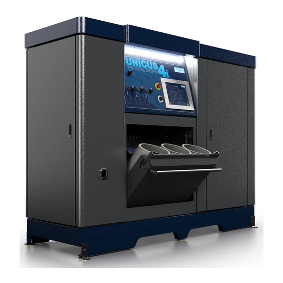
- Page 1 Instruction Manual and Replacement Parts List Stationary Integrated Systems High Pressure Breathing Air System UNICUS 4i - 25...
- Page 2 UNICUS 4i WARNING 1st Edition May 1993 Date Notes Auth 2nd Edition; March 15, 2017 Date Notes Auth...
- Page 3 MNL-0021 FCC Compliance Statement...
- Page 4 UNICUS 4i Table of Contents CHAPTER 1:- - - - - - - - - - - - - - - - - - - - - INTRODUCTION HOW TO USE THIS MANUAL HOW TO USE THE REPLACEMENT PARTS LIST HOW TO USE THE APPENDIX UNIT SPECIFICATIONS COMPONENT LOCATIONS...
- Page 5 MNL-0021 AUTOMATIC CONDENSATE DRAIN SYSTEM; ASY-4002 CONDENSATE COLLECTOR CHAPTER 4: - - - - - - - - - - - - - - - - PURIFICATION SYSTEM INTRODUCTION...
- Page 6 UNICUS 4i 1P5S SECURUS II® PURIFICATION SYSTEM COMPONENT DESCRIPTION MAINTENANCE REPLACEMENT PARTS LIST CHAPTER 5:- - - - - - - - - - - COMPRESSOR DRIVE; UNICUS 4I VERTICAL COMPRESSOR DRIVE MAINTENANCE OF THE V-BELT AND SHEAVES REPLACEMENT PART LIST CHAPTER 6:- - - - - - - - - - - - -ELECTRICAL PANEL, ASY-1191 OVERVIEW ELECTRICAL PANEL...
- Page 7 MNL-0021 REPLACEMENT PARTS LIST CHAPTER 7: - - - - - - - - - - - - - - - - - - - - - - -RFID OPTION DESCRIPTION COMPONENTS FUNCTIONS REPLACEMENT PARTS LIST CHAPTER 8: - - - - - - - - - - - - - - - - ENMET GAS MONITORS DESCRIPTION OPERATION CALIBRATION...
- Page 8 UNICUS 4i 10.3 AUTOCASCADE SYSTEM CHAPTER 11: - - - - - - - - - - - - - - - - - - - - - - - -APPENDIX 11.1 SAFETY 11.2 UNPACKING, HANDLING AND INSTALLATION 11.3 LONG TERM STORAGE 11.4 REPRODUCIBLE FORMS 11.5 REFERENCE DATA 11.6 ADDITIONAL DOCUMENTS...
- Page 9 MNL-0021 List of Figures CHAPTER 1: - - - - - - - - - - - - - - - - - - - - - INTRODUCTION CHAPTER 2: - - - - - - - - - - - - - - OPERATING INSTRUCTIONS CHAPTER 3: - - - - - - - - - - - - IK 18.1 II COMPRESSOR BLOCK...
- Page 10 UNICUS 4i CHAPTER 4:- - - - - - - - - - - - - - - - -PURIFICATION SYSTEM...
- Page 11 MNL-0021 CHAPTER 5: - - - - - - - - - - - COMPRESSOR DRIVE; UNICUS 4I CHAPTER 6: - - - - - - - - - - - - ELECTRICAL PANEL, ASY-1191 CHAPTER 7: - - - - - - - - - - - - - - - - - - - - - - -RFID OPTION CHAPTER 8: - - - - - - - - - - - - - - - - ENMET GAS MONITORS CHAPTER 9: - - - - - - - - - - - - - - - - - CFS III MAINTENANCE...
- Page 12 UNICUS 4i CHAPTER 10: - - - - - - - - - - - - - UNICUS III HP AIR STORAGE CHAPTER 11: - - - - - - - - - - - - - - - - - - - - - - - -APPENDIX...
- Page 13 MNL-0021 CHAPTER 1: INTRODUCTION 1.1 How To Use This Manual NOTICE 1.1.1 Manual Safety Notices DANGER WARNING...
- Page 14 UNICUS 4i CAUTION NOTICE 1.2 How to Use the Replacement Parts List Information Example...
- Page 15 MNL-0021 Figure 1-1 WARNING 1.3 How to Use the Appendix...
- Page 16 UNICUS 4i 1.4 Unit Specifications 1.4.1 UNICUS 4i - 25 1.4.1.1 1.4.1.2 Voltage Frequency Phase Power Type 1.4.1.3...
- Page 17 MNL-0021 1.5 Component Locations Figure 1-2...
- Page 18 UNICUS 4i Figure 1-3...
- Page 19 MNL-0021 Figure 1-4...
- Page 20 UNICUS 4i CHAPTER 2: OPERATING INSTRUCTIONS Figure 2-1 2.1 Emergency Stop Button 2.2 Operator Interface 2.2.1 Badge Screen...
- Page 21 MNL-0021 Figure 2-2 2.2.2 Admin. Main Menu Screen Figure 2-3...
- Page 22 UNICUS 4i 2.2.2.1 Figure 2-4...
- Page 23 MNL-0021 Figure 2-5 2.2.2.2 Figure 2-6...
- Page 24 UNICUS 4i Figure 2-7 2.2.2.3 Figure 2-8...
- Page 25 MNL-0021 2.2.2.3.1 Figure 2-9 2.2.2.3.2 Figure 2-10...
- Page 26 UNICUS 4i 2.2.2.3.3 2.2.2.3.4 2.2.2.4 Figure 2-11 2.2.2.5...
- Page 27 MNL-0021 Figure 2-12 2.2.3 Home Screen Figure 2-13...
- Page 28 UNICUS 4i 2.2.3.1 Figure 2-14 2.2.3.2...
- Page 29 MNL-0021 Figure 2-15 WARNING 2.2.3.3...
- Page 30 UNICUS 4i 2.3 Fill Station Operation. WARNING WARNING Figure 2-16 CAUTION...
- Page 31 MNL-0021 NOTICE Figure 2-17 Filling the Bottle Connecting the Air Bottle Disconnecting the Air Bottle 2.3.1 Remote Fill Connection...
- Page 32 UNICUS 4i 2.3.1.1 2.3.1.2 2.3.1.3...
- Page 33 MNL-0021 CHAPTER 3: IK 18.1 II COMPRESSOR BLOCK 3.1 Description 3.1.1 Component Location Figure 3-1...
- Page 34 UNICUS 4i 3.1.2 Air Flow Diagram Figure 3-2 3.1.3 Lubrication System 3.1.3.1 CAUTION...
- Page 35 MNL-0021 Figure 3-3 Figure 3-4 3.1.3.2 3.1.3.3 3.1.3.4 3.1.3.5 CAUTION...
- Page 36 UNICUS 4i Figure 3-5 Figure 3-6 Figure 3-7...
- Page 37 MNL-0021 3.1.3.6 CAUTION 3.1.4 Intake Filter Figure 3-8 3.1.4.1 3.1.4.2...
- Page 38 UNICUS 4i WARNING 3.1.5 Interstage Separators 3.1.5.1...
- Page 39 MNL-0021 3.1.5.2 Figure 3-9 Figure 3-10...
- Page 40 UNICUS 4i Figure 3-11 3.1.6 Compressor Valves and Valve Heads 3.1.6.1...
- Page 41 MNL-0021 Figure 3-12 Figure 3-13 3.1.6.2 WARNING 3.1.6.3...
- Page 42 UNICUS 4i 3.1.6.4 Figure 3-14 3.1.6.4.1 3.1.6.4.2...
- Page 43 MNL-0021 3.1.6.5 Figure 3-15 3.1.6.5.1 3.1.6.5.2 CAUTION...