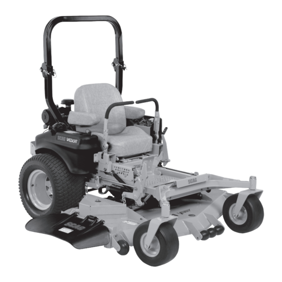
Scag Power Equipment Wildcat STWC52V-26KA-LC Operator's Manual
Scag power equipment push lawn mower operator's manual
Hide thumbs
Also See for Wildcat STWC52V-26KA-LC:
- Operator's manual (122 pages) ,
- Illustrated parts manual (34 pages) ,
- Operator's manual (82 pages)
Table of Contents
Advertisement
Congratulations on owning a Scag mower! This manual contains the operating
instructions and safety information for your Scag mower. Reading this manual
can provide you with assistance in maintenance and adjustment procedures to
keep your mower performing to maximum efficiency. The specific models that
this book covers are listed on the inside cover. Before operating your machine,
please read all the information enclosed.
© 2008
Scag Power Equipment
Division of Metalcraft of Mayville, Inc.
OPERATOR'S
MANUAL
Wildcat
Models:
STWC52V-25KA
STWC52V-26KA-LC
STWC61V-26KA-LC
STWC61V-27CV
PART NO. 03220 Rev. 1
PRINTED 3/2008
PRINTED IN USA
Advertisement
Chapters
Table of Contents

Related Manuals for Scag Power Equipment Wildcat STWC52V-26KA-LC


Summary of Contents for Scag Power Equipment Wildcat STWC52V-26KA-LC
- Page 1 The specific models that this book covers are listed on the inside cover. Before operating your machine, please read all the information enclosed. © 2008 Scag Power Equipment Division of Metalcraft of Mayville, Inc. OPERATOR’S MANUAL...
- Page 2 HAzARD CONTROL AND ACCIDENT PREvENTION ARE DEPENDENT UPON THE AWARENESS, CONCERN, PRUDENCE, AND PROPER TRAINING OF THE PERSONNEL INvOLvED IN THE OPERATION, TRANSPORT, MAINTENANCE, AND STORAGE OF THE EqUIPMENT. This manual covers the operating instructions and illustrated parts list for: STWC52v-25KA STWC52v-26KA-LC STWC61v-26KA-LC STWC61v-27Cv SMWC-52v SMWC-61v Always use the entire serial number listed on the serial number tag when referring to this product.
-
Page 3: Table Of Contents
Table of Contents SECTION 1 - GENERAL INFORMATION 1.1 INTRODUCTION ...1 1.2 DIRECTION REFERENCE ...1 1.3 SERvICING THE ENGINE AND DRIvE TRAIN COMPONENTS ...1 1.4 SYMBOLS ...2 SECTION 2 - SAFETY INFORMATION 2.1 INTRODUCTION ...3 2.2 SIGNAL WORDS ...3 2.3 BEFORE OPERATION CONSIDERATIONS ...3 2.4 OPERATION CONSIDERATIONS ...4 2.5 ROLL-OvER PROTECTION SYSTEM ...6 2.6 MAINTENANCE CONSIDERATIONS &... - Page 4 SECTION 6 - ADJUSTMENTS 6.1 PARKING BRAKE ADJUSTMENT ...22 6.2 TRAvEL ADJUSTMENTS ...22 6.3 THROTTLE CONTROL AND CHOKE ADJUSTMENTS ...24 6.4 BELT ADJUSTMENT ...24 6.5 BELT ALIGNMENT ...24 6.6 CUTTER DECK ADJUSTMENTS ...24 6.7 CUSTOM-CUT BAFFLE ADJUSTMENT ...26 SECTION 7 - MAINTENANCE 7.1 MAINTENANCE CHART - RECOMMENDED SERvICE INTERvALS ...28 7.2 LUBRICATION ...29...
-
Page 5: General Information
All information is based upon product information available at the time of approval for printing. Scag Power Equipment reserves the right to make changes at any time without notice and without incurring any obligation. -
Page 6: Symbols
SYMBOLS SYMBOL DESCRIPTION Choke Parking Brake On/Start Off/Stop Falling Hazard Fast Continuously Variable - Linear Pinch Point 481039S Hour meter/Elapsed Operating Hours STT MODELS Seat must be installed under the seat hold down bracket during installation. Failure to secure the seat under the hold down bracket could result in serious injury or death in a roll over. -
Page 7: Safety Information
Section 2 INTRODUCTION Your mower is only as safe as the operator. Carelessness or operator error may result in serious bodily injury or death. Hazard control and accident prevention are dependent upon the awareness, concern, prudence, and proper training of the personnel involved in the operation, transport, maintenance and storage of the equipment. -
Page 8: Operation Considerations
If the operator(s) or mechanic(s) cannot read English or Spanish, it is the owner's responsibility to explain this material to them. DO NOT wear loose fitting clothing. Loose clothing, jewelry or long hair could get tangled in moving parts. Do not operate the machine wearing shorts; always wear adequate protective clothing including long pants. - Page 9 Section 2 To prevent tipping or loss of control, start and stop smoothly, avoid unnecessary turns and travel at reduced speed. When using any attachment, never direct the discharge of material toward bystanders or allow anyone near the machine while in operation. Before attempting to start the engine, with the operator in the seat, disengage power to the cutter deck, place the steering control levers in the neutral...
-
Page 10: Roll-Over Protection System
ROLL-OvER PROTECTION SYSTEM WARNING Reduce speed when turning, operating on slopes, slick or wet surfaces. Allow extra distance to stop. Stay off of slopes too steep for safe operation. To check a slope, attempt to back up it (with the cutter deck down). - Page 11 Section 2 Remove the hairpin cotter pins and remove the two (2) lock pins. See Figure 2-2. Lower the roll bar to the down position. To raise the roll bar, lift the bar to the upright position. Install the two (2) lock pins through the hole, secure with the two (2) hairpin cotter pins and tighten the tension knobs.
-
Page 12: Maintenance Considerations & Storage
MAINTENANCE CONSIDERATIONS & STORAGE Never make adjustments to the machine with the engine running unless specifically instructed to do so. If the engine is running, keep hands, feet, and clothing away from moving parts. Disengage drives, lower implement, set parking brake, stop engine and remove key or disconnect spark plug wire to prevent accidental starting of the engine when servicing or adjusting the machine. -
Page 13: Safety And Instructional Decals
Section 2 SAFETY AND INSTRUCTIONAL DECALS CAUTION Avoid injury from burns. Shut off engine before removing fuel tank cap. Molded in Fuel Tank START / DRIVE PROCEDURE WARNING AVOID SERIOUS INJURY OR DEATH 483444 483444 INSTALL BELT COvER BEFORE 483407 FORWARD 483406 483633... -
Page 14: Specifications
Brand ...Kawasaki, Kohler Horsepower: Scag Model STWC52V-25KA ...25 hp (Spec. #FH721V-CS30-R) Scag Model STWC52V-26KA-LC, STWC61V-26KA-LC ... 26 hp (Spec. #FD731D-BS05) Scag Model STWC61V-27CV ... 27 hp (Spec. #CV740-3110) Type ...4 Cycle Gasoline, Twin Cylinder, Vertical Shaft Cylinders ... 2 with Cast Iron Sleeves Governor ...Mechanical Type with Variable Speed Control Set At 3600 RPM... -
Page 15: Cutter Deck
Section 3 Seat ... Padded, Thick Cushion with Extra Spring Support Travel Speed: Forward ...0-10 MPH Reverse ...0-5 MPH -NOTE- The machine will travel at 10 mph for transport purposes. For best cutting performance the forward travel speed should be adjusted depending upon the cutting conditions. CUTTER DECK Type ... -
Page 16: Operating Instructions
OPERATING INSTRUCTIONS CAUTION Do not attempt to operate this mower unless you have read this manual. Learn the location and purpose of all controls and instruments before you operate this mower. CONTROLS AND INSTRUMENT IDENTIFICATION Before operating the mower, familiarize yourself with all mower and engine controls. -
Page 17: Safety Interlock System
Section 4 Fuse Holders (Figure 4-1). Two 20-amp fuses protect the mower’s electrical system. To replace fuses, pull fuse out of the socket and install a new fuse. Left Steering Control (Figure 4-1). the mower's left wheel when traveling forward or reverse. -
Page 18: Starting The Engine
STARTING THE ENGINE CAUTION DO NOT USE STARTING FLUIDS. Use of starting fluids in the air intake system may be potentially explosive or cause a “runaway” engine condition that could result in engine damage and/or personal injury. Be sure the fuel shutoff valve, located behind the operator's seat, is completely open. -
Page 19: Engaging The Deck Drive (Cutter Blades)
Section 4 REvERSE TRAvEL CAUTION Disengage power to the mower before backing up. Do not mow in reverse unless absolutely necessary and then only after observation of the entire area behind the mower. CAUTION Before backing up, observe the rear for persons and obstructions. -
Page 20: Hillside Operation
HILLSIDE OPERATION WARNING DO NOT operate on steep slopes. To check a slope, attempt to back up it (with the cutter deck down). If the machine can back up the slope without the wheels slipping, reduce speed and use extreme caution. -
Page 21: Moving Mower With Engine Stopped
Section 4 4.11 MOvING MOWER WITH ENGINE STOPPED To “free-wheel” or move the mower around without the engine running, rotate the dump valve levers counter-clockwise open. See Figure 4-4. Disengage the parking brake and move the mower by hand. When the machine is in the desired position, engage the parking brake and rotate the levers clockwise until they stop (closed). -
Page 22: Adjusting The Steering Levers
Insert the lanyard pin into the cutting height index at the desired cutting height. Push forward on the deck lift foot lever, hold in place and pull back on the deck release lever. See Figure 4-6. Slowly release the foot pedal. -
Page 23: Troubleshooting Cutting Conditions
Section 5 TROUBLESHOOTING CUTTING CONDITIONS CONDITION STRINGERS - OCCASIONAL BLADES OF UNCUT GRASS Width of Deck SGB020 STREAKING - STRIPS OF UNCUT GRASS IN CUTTING PATH Width of Deck SGB018 STREAKING - STRIPS OF UNCUT GRASS BETWEEN CUTTING PATHS Width Width Deck Deck... - Page 24 TROUBLESHOOTING CUTTING CONDITIONS (CONT'D) CONDITION U N E v E N C U T O N F L AT GROUND - WAvY HIGH-LOW APPEARANCE, SCALLOPED CUT, OR ROUGH CONTOUR Width of Deck SGB020 UNEvEN CUT ON UNEvEN GROUND - WAvY APPEARANCE, HIGH-LOW SCALLOPED CUT, OR ROUGH CONTOUR Width of Deck...
- Page 25 Section 5 TROUBLESHOOTING CUTTING CONDITIONS (CONT'D) CONDITION SCALPING - BLADES HITTING DIRT OR CUTTING vERY CLOSE TO THE GROUND Width of Deck SGB022 STEP CUT - RIDGE IN CENTER OF CUTTING PATH Width of Deck SGB024 SLOPE CUT - SLOPING RIDGES ACROSS WIDTH OF CUTTING PATH Width of Deck...
-
Page 26: Adjustments
PARKING BRAKE ADJUSTMENT WARNING Do not operate the mower if the parking brake is not operable. Possible severe injury could result. The parking brake linkage should be adjusted whenever the parking brake lever is placed in the “ENGAGE” position and the parking brake will allow the mower to move. If the following procedures do not allow you to engage the parking brake properly, contact your Scag dealer for further brake adjustments. - Page 27 Section 6 NEUTRAL ADJUSTMENT Be sure the dump valve levers are in the run position and the steering control levers are in the neutral lock position. With an operator in the seat, start the engine and disengage the parking brake. Run the engine at full operating speed and check if the machine creeps forward or backwards.
-
Page 28: Throttle Control And Choke Adjustments
If at full speed the mower pulls left, it is an indication that the right wheel is turning faster than the left wheel. To adjust this condition, proceed as follows: A. Stop the machine and place the steering control levers in the neutral position. Loosen the lock nuts securing the ball joints at each end of the RH steering control rod. - Page 29 Section 6 CUTTER DECK PITCH The pitch of the cutter deck should be equal between the front and rear of the cutter deck for proper cutting performance. To check for proper deck pitch, be sure that the mower is on a flat, level surface and the tires are properly inflated.
-
Page 30: Custom-Cut Baffle Adjustment
Check the cutter deck cutting height by placing the lanyard pin in the 3" position on the cutting height index. Release the deck from the transport position and allow the deck to move to the 3" cutting height position. Check the measurement from the floor to the cutter blade tip. - Page 31 Section 6 Mounting Slot Figure 6-8. Mounting Slot Selected Figure 6-9. Custom-Cut Baffle Adjustment Mounting Hardware Location Slot “A” Hole 1 Height (inches) 3” 3-Position Custom-Cut Baffle Adjustment Custom-Cut Baffle Adjustment Mounting Hardware Location Slot “A” Hole 1 Hole 2 Height (inches) 3-3/4”...
-
Page 32: Maintenance
MAINTENANCE CHART - RECOMMENDED SERvICE INTERvALS HOURS BREAK-IN 100 200 500 (FIRST 10) * Perform these maintenance procedures more frequently under extreme dusty or dirty conditions MAINTENANCE PROCEDURE Check all hardware for tightness Check hydraulic oil level C h e c k a l l b e l t s f o r p r o p e r alignment Change engine oil and filter Check coolant level... -
Page 33: Lubrication
Section 7 MAINTENANCE CHART - RECOMMENDED SERvICE INTERvALS (CONT'D) HOURS BREAK-IN (FIRST 10) LUBRICATION GREASE FITTING LUBRICATION CHART (SEE FIGURE 7-1) LOCATION 1 Caster Wheel Pivot * 2 Caster Wheel Bearings 3 Brake Actuator 4 Cutter Deck Bellcranks 5 Cutter Deck Pusharms 6 Control Pivot 6 Cutter Deck Spindle 7 Brake Handle... - Page 34 Figure 7-1. GREASE FITTING LUBRICATION Lubricant Interval Lithium MP White Grease 2125 (40 Hours/Weekly) Chassis Grease (100 Hours/Bi-monthly) Chassis Grease (200 Hours/Monthly) Chassis Grease (500 Hours/Yearly) Lubrication Fitting Points Section 7...
-
Page 35: Hydraulic System
Section 7 HYDRAULIC SYSTEM A. CHECKING HYDRAULIC OIL LEvEL The hydraulic oil level should be checked after the first 10 hours of operation. Thereafter, check the oil after every 200 hours of machine operation or monthly, whichever occurs first. - IMPORTANT - If the oil level is consistently low, check for leaks and correct immediately. -
Page 36: Engine Oil
C. CHANGING HYDRAULIC OIL FILTER ELEMENT The hydraulic oil filter should be changed after every 500 hours of operation or annually, whichever occurs first. Remove the oil filter element and properly discard it. See Figure 7-3. Fill the new filter with clean oil and install the filter. -
Page 37: Engine Air Cleaner
Section 7 Remove the machine from the truck or trailer and fuel on the ground. If this is not possible, then refuel the machine with a portable container, rather than from a gasoline dispenser nozzle. Keep the nozzle in contact with the rim of fuel tank or container opening at all times until fueling is complete. -
Page 38: Battery
BATTERY WARNING Lead-acid batteries produce flammable and explosive gases. To avoid personal injury when checking, testing or charging batteries, DO NOT use smoking materials near batteries. Keep arcs, sparks and flames away from batteries. Provide proper ventilation and wear safety glasses. WARNING Battery posts, terminals, and related accessories contain lead and lead compounds, chemicals... -
Page 39: Drive Belts
Section 7 DRIvE BELTS All drive belts are spring-loaded and self-tensioning, however after the first 2, 4, 8 and 10 hours of operation, the belts should be checked for proper alignment and wear. Thereafter, check the belts after every 40 hours of operation or weekly, whichever occurs first. -
Page 40: Tires
- NOTe - The front of the machine will have to be raised slightly to remove the blade bolt from the cutter spindle. To install the new cutter blade, put the flat washer onto the blade bolt and slide the bolt into the hole in the cutter blade. -
Page 41: Body, Deck, And Upholstery
Section 7 Replace the radiator cap. Push down on the cap and turn clockwise until it stops. - NOTe - The cooling system should be flushed and the coolant replaced every 500 hours of operation or annually. See your Scag dealer for proper coolant replacement. - Page 42 Section 7 NOTES...
-
Page 43: Illustrated Parts List
Section 8 ILLUSTRATED PARTS LIST SCAG APPROvED ATTACHMENTS AND ACCESSORIES Attachments and accessories manufactured by companies other than Scag Power Equipment are not approved for use on this machine. Scag approved attachments and accessories: • GC-STC-V, GC-STWC-61V (p/n 9057, p/n 9058) 61" Decks •... -
Page 44: 52V Cutter Deck
6 7 8 5 25 * 52" cutter deck has a notch for anti-scalp roller 52v CUTTER DECK Section 8 64 60 62 61 59 58 66 63 STC 2006 CD4852 Rev.1... - Page 45 Section 8 Ref. Part No. Description 461858 Cutter Deck Velocity Plus 43686 Boss, Spring Anchor 04019-04 Nut, 3/8-16 Serr. Flng. 481625-01 Wing Nut, 3/8-16 481632 Anti-Scalp Wheel 04003-26 Bolt, Carriage 3/8-16 x 4” 422478 Bracket, Anti-Scalp Wheel 04017-27 Bolt, Serr. Flng. 3/8-16 x 1” 04043-06 Flatwasher, 5/8”...
-
Page 46: Cutter Deck
6 7 8 5 25 61v CUTTER DECK "A" "A" 2 80 Section 8 64 60 62 61 59 58 66 63 STWC 2006 CD61... - Page 47 Section 8 Ref. Part No. Description 461862 Cutter Deck Velocity Plus 43687 Boss, Spring Anchor 424371 Bracket, LH Spring Anchor 61V 481625-01 Wing Nut, 3/8-16 481632 Anti-Scalp Wheel 04003-26 Bolt, Carriage 3/8-16 x 4” 422478 Bracket, Anti-Scalp Wheel 04017-27 Bolt, Serr. Flng. 3/8-16 x 1” 04043-06 Flatwasher, 5/8”...
-
Page 48: Cutter Deck Controls
CUTTER DECK CONTROLS Section 8 CUTTER DECK STC 2006 CDC... - Page 49 Section 8 Ref. Part No. Description 482624 Rod, Deck Lift Linkage 04020-28 Nut, Jam 1/2-20 LH Thread 481766 Rod End, 1/2-20 Female LH Thread 04050-10 Retaining Ring, 1/2” Ext. “E” 483062 Slide, Deck Height Adjust 43487 Pin, Deck Lift 423463 Bracket, Cutting Height Adjustment 04001-22 Bolt, Hex Hd.
-
Page 50: Sheet Metal Components
SHEET METAL COMPONENTS 18 19 Section 8 26hp Kawasaki 7 8 20 STWC 2008 SMC... - Page 51 Section 8 Ref. Part No. Description 461918 Main Frame Assembly w/Decals 04001-73 Bolt, Hex Hd. 5/16-18 x 3-3/4” 482938 Back Cover 04019-04 Nut, Serr. Flng. 3/8-16 461989 Plate, Seat Mounting 482939 Cushion Cover 43462 Pin Retainer, Spring 481389 Spring Battery (not available through Scag) 423571 Battery Cover 482553...
-
Page 52: Stwc Roll-Over Protection System
Section 8 STWC ROLL-OvER PROTECTION SYSTEM STWC 2007 ROPS... - Page 53 Section 8 STWC ROLL-OvER PROTECTION SYSTEM Ref. Part No. Description 461956 STWC Foldable ROPS 04001-145 Bolt, Hex Hd. 1/2-13 x 3-1/2” 04021-19 Nut, Center Lock 1/2-13 483412 Retractable Seat Belt 04040-13 Flatwasher, 1/2 (.562 x 1.375 x .109") 481625-03 Thumb Screw, 5/16-18 NC x 3/4” 04062-06 Hair Pin, Cotter 483262...
-
Page 54: Drive System Components
DRIvE SYSTEM COMPONENTS Section 8 STWC 2008 DSC... - Page 55 Section 8 Ref. Part No. Description 04021-09 Nut, Elastic Stop 3/8-16 04019-04 Nut, Serr. Flng. 3/8-16 483087 Spring, Pump Idler 43286 Spacer 04001-22 Bolt, Hex Hd. 3/8-16 x 2-3/4” 461603 Idler Arm Assy., Pump Drive 04063-14 Key, 5 x 5 x 25mm 483172 Belt, Transmission 483415...
-
Page 56: Engine And Attaching Parts
Section 8 ENGINE AND ATTACHING PARTS SC 2004 EAPKA... - Page 57 Section 8 ENGINE AND ATTACHING PARTS Ref. Part No. Description 482900 Engine, 27HP Kohler 482827 Engine, 25HP Kawasaki 483126 Engine, 26HP Kawasaki Liquid-Cooled 423770 Bumper, Rear 41031 Weight, Rear (Shield) 61V Only 424107 Shield, Rear 52V Only 04019-04 Nut, Serr. Flng. 3/8-16 482349 Extension, Oil Drain 4”...
-
Page 58: Steering Components
STEERING COMPONENTS 29, 29A Section 8 To Pump STC 2006 SSC REV 1... - Page 59 Section 8 Ref. Part No. Description 482340 Grip, Control Lever 461914 Handle Bar, LH (Incl. item 1) 461923 Handle Bar, RH (Incl. item 1) 04001-09 Bolt, Hex Hd. 5/16-18 x 1” 04030-03 Lockwasher, 5/16” 483269 Knob 04040-15 Flatwasher, 5/16 (.375 x .875 x .083") 04060-01 Roll Pin, Spring 5/32 x 3/4”...
-
Page 60: Brake Components
40 16 17 35 31 11 3 BRAKE COMPONENTS Section 8 15 14 13 12 STC 2002 BSC... - Page 61 Section 8 Ref. Part No. Description 04019-06 Nut, Serr. Flng. 1/2-13 48807 Spring 04001-08 Bolt, Hex Hd. 5/16-18 x 3/4” 04001-163 Bolt, Hex Hd. 1/2-13 x 3-3/4” 04001-52 Bolt, Hex Hd. 1/2-13 x 2-1/2” 04021-19 Nut, 1/2-13 Center Lock 483190 Wheel Motor, Hydro-Gear 04063-25 Key, Woodruff 5/16 x 1”...
-
Page 62: Fuel And Hydraulic System
FUEL AND HYDRAULIC SYSTEM 3 55 45 46 18 19 33 47 48 ENGINE 35 32 54 48 47 49 Section 8 20 19 STWC 2005 FHS... - Page 63 Section 8 FUEL AND HYDRAULIC SYSTEM Ref. Part No. Description 482643 Pump, BDP-10A-316 (LH) 482644 Pump, BDP-10A-419 (RH) 482266-01 Elbow, 90 Degree 9/16" O-Ring x 3/8" Hose 48572-02 Fitting, 1/2” JIC x 5/8" O-Ring 48811 Hose, 3/8" Pushlock (Specify length) 482573 Bushing 482574...
-
Page 64: Electrical System - Kohler & Kawasaki Air-Cooled
ELECTRICAL SYSTEM - KOHLER & KAWASAKI AIR-COOLED Section 8 STWC 2008 ESKH... - Page 65 Section 8 ELECTRICAL SYSTEM - KOHLER & KAWASAKI AIR-COOLED Ref. Part No. Description 483355 Hourmeter 48298 Fuse, 20 Amp 483366 Key, Ignition 462069 Key Assembly w/Fob 48017-04 Nut, Hex 5/8-32 48017-03 Lockwasher, 5/8” Internal 461660 Electric PTO Clutch GT3.5 48798 Switch, Ignition 483162 Switch, PTO...
-
Page 66: Electrical System - 26Hp Kawasaki Liquid-Cooled
ELECTRICAL SYSTEM - 26HP KAWASAKI LIqUID-COOLED Section 8 STWC 2008 ESKALC... - Page 67 Section 8 ELECTRICAL SYSTEM 26HP KAWASAKI LIqUID-COOLED Ref. Part No. Description 483355 Hourmeter 48298 Fuse, 20 amp 483366 Key, Ignition 462069 Key Assembly w/Fob 48017-04 Nut, Hex 5/8-32 48017-03 Lockwasher, 5/8” Internal 461660 Electric PTO Clutch GT3.5 48798 Switch, Ignition 483162 Switch, PTO 48788...
-
Page 68: Hydraulic Pump Assembly
PORT "A" SIDE HYDRAULIC PUMP ASSEMBLY PORT "B" SIDE Section 8... - Page 69 Section 8 Ref. Part No. Description HG 70516 Housing Kit HG 70573 End Cap Kit HG 50641 Straight Headless Pin HG 50969 Hex Flng. Bolt, M8-1.25 x 60mm HG 51232 Housing O-Ring HG 2513027 Charge Pump Kit HG 50273 Gerotor Assembly HG 9004101-1340 O-Ring HG 50095...
-
Page 70: Replacement Decals And Information Plates
REPLACEMENT DECALS AND INFORMATION PLATES FORWARD REvERSE 482100 WARNING INSTALL BELT COvER BEFORE OPERATING MACHINE READ OPERATOR'S MANUAL MANUFACTURED UNDER ONE OR MORE OF THE FOLLOWING PATENTS: 4,487,006 4,885,903 4,920,733 4,967,543 4,991,382 4,998,948 5,042,239 5,117,617 5,133,176 5,826,416 5,832,708 5,865,018 6,192,666 6,766,633 6,892,519 6,996,962... - Page 71 Section 8 REPLACEMENT DECALS AND INFORMATION PLATES Ref. Part No. Description 483407 Decal, Danger-Spinning Blades 483406 Decal, Warning-Rotating Blades 483200 Decal, 52V 483201 Decal, 61V 483158 Decal, ROPS 483044 Decal, Patents 482100 Decal, Traction Control 481971 Decal, Heavy Duty Commercial 48404 Decal, Metalcraft - Made in USA 483402...
-
Page 72: Electrical Schematic - Kohler & Kawasaki Air-Cooled
ELECTRICAL SCHEMATIC - KOHLER & KAWASAKI AIR-COOLED KAWASAKI ADAPTER HARNESS MAGNETO WHITE FUEL SOLENOID RED W/YEL STRIPE YELLOW RECTIFIER GRN W/WHT STRIPE SOLENOID MAIN HARNESS KOHLER ADAPTER HARNESS GRN W/WHT STRIPE WHITE ENGINE PLUG YELLOW SOLENOID "B+" MAIN HARNESS BLACK BLACK BLACK GROUND... -
Page 73: Electrical Schematic - 26Hp Kawasaki Liquid-Cooled
Section 8 ELECTRICAL SCHEMATIC - 26HP KAWASAKI LIqUID-COOLED SWITCH BLACK BLACK BLACK GROUND HOURMETER MAIN HARNESS WATER TEMP GAUGE SWITCH 20 AMP FUSES CLUTCH ENGINE ADAPTER HARNESS ADAPTER HARNESS WHITE YELLOW GRN W/WHT STRIPE WHITE W/BLACK STRIPE RED W/YEL STRIPE RELAY BRAKE INTERLOCK... - Page 74 Section 8 Notes...
-
Page 75: Limited Warranty - Commercial Equipment
Cutter decks are warranted against cracking for a period of three (3) years. (Parts and labor 1st and 2nd year; Parts only 3rd year.) The repair or replacement of the cutter deck will be at the option of Scag Power Equipment. We reserve the right to request components for evaluation. - Page 76 (Piezas y mano de obra) (La garantía de dos años no incluye las conexiones, mangueras, las correas de transmisión). La reparación o el reemplazo de la bomba hidráulica o el motor hidráulico estarán sujetos a discreción de Scag Power Equipment.
- Page 77 Notas Sección...
- Page 78 cerrojo. radiador desechos desechos. retirar aire sólo agua; rocíe Jamás comprimido. aire desechos demasiados tiene radiador -NOTA- agua. manguera comprimido aire desechos desechos Criba 7-11 STWC ella tire desechos criba comprimido. aire usar seguridad siempre personales, daños PRECAUCIÓN: radiador. criba limpie retire operación,...
- Page 79 protección máxima para automotriz cortacésped Encere Scag. autorizado disponible 48521) (N/P Scag pintura dañadas metal superficies asiento. limpiar para limpiador jabón suave eléctricos. componentes presión. limpiadores limpiadores fría agua corte. cortacésped lave uso, cada aire motor; lave mientras equipo parte ninguna PRECAUCIÓN: TAPICERÍA...
- Page 80 caiga evitar para corte más posición amarre posición cortacésped plataforma reemplazar antes encendido corte. cuchillas trabajar para apropiada protección ADVERTENCIA: cuchilla mismo. balancear prefiere especiales cuchilla balancear para distribuidor Consulte prematuro. vibración producirse puede están cuchillas cuchilla. cuchillas Afilado SGB033 cuchilla ancho exceder...
- Page 81 batería. negativo cable luego batería positivo cable conecte puente, cables negativo. tierra debe puente, arranque para vehículo voltios. debe arranque auxiliar puente enfriamiento. temporalmente detenerse reducirse (125°F), 52°C excede temperatura excesiva electrolito derrame produce (encima caliente está batería demasiado arrojan gases, excesivos satisfactorias...
-
Page 82: Remolque
motor. fabricante recomienda pre-filtro aire filtro reemplace inspecciónelo. aire costado. retire aire filtro filtro cubierta fijan seguros motor. daños prevenir veces elemento puede polvo mucho -NOTA- necesario. elemento ocurra semanas, cada cada después aire filtro aire. filtro servicio períodos operación ambiente aire, elemento... - Page 83 gasolina. para aprobado recipiente ignición. otras pipas puros, cigarrillos, vapores inflamable gasolina gasolina. manipular propiedad, daños personales mínimo octanaje limpia, gasolina demasiado. cuello debajo pulgada día cada inicio combustible combustible tanque rellenar. combustible tapa quitar antes enfríe permita quemaduras, PELIGRO: COMBUSTIBLE motor operador...
- Page 84 página. siguiente filtro elemento Cambio describe como aceite filtro hidráulico, aceite depósito -NOTA- ajustado. asegúrese drenaje tapón drenaje Tapón hidráulico aceite STC2001HODP HIDRÁULICO HIDRÁULICO ACEITE DRENAJE TAPÓN apropiadamente. deséchelo recipiente drenar Permita 7-3). Figura (Vea frontal lado drenaje drenaje tapón depósito Quite adelante.
- Page 85 conexión horas/anualmente) chasis Grasa horas/mensualmente) chasis Grasa meses) horas/cada chasis Grasa horas/semanalmente) 2125 litio blanca Grasa lubricación LUBRICACIÓN GRASA CONEXIONES puntos Lubricación (500 (200 (100 Intervalo Figura Sección...
- Page 86 industriales servicio grasa. tapa instalación grasa. tapa instalar Vuelva superior parte grasa nueva aparezca parte número tapón, chasis 2125 litio blanca chasis chasis chasis chasis chasis chasis UBICACIONES LUBRICANTE Nº 7-1) FIGURA Scag distribuidor Consulte párrafo 20W50 motor para aceite párrafo párrafo párrafo...
- Page 87 extremas condiciones bajo párrafo aire párrafo párrafo párrafo párrafo párrafo filtro 7.10 párrafo párrafo cuchillas párrafo 7.11 párrafo párrafo párrafo motor párrafo seguridad párrafo hidráulicas mangueras verificar cuidado mucho Tenga párrafo párrafo hidráulico Observaciones RECOMENDADOS mantenimiento procedimientos filtro elemento *Limpie motor aceite Cambie...
- Page 88 4" personalizado corte deflector Posición TOPE PLANA ELÁSTICA TUERCA ARANDELA Setting 4" 2004 CARRO PERNO 3-1/2" personalizado corte deflector Posición TOPE PLANA ELÁSTICA TUERCA ARANDELA Setting 3-1/2" 2004 CARRO PERNO 3" personalizado corte deflector Posición TOPE PLANA ELÁSTICA TUERCA ARANDELA Setting 3"...
- Page 89 óptimo. desempeño posiciones tres colocar cortando. está césped tipo desempeño precisa para bajarse levantarse deflector césped. tipo corte desempeño aire flujo para diseñado está personalizado personalizado corte transporte. posición bloquear pueda corte asegúrese ajuste, realizar -NOTA- Figura (Vea plataforma. varilla utilizando ajuste realizarse...
- Page 90 bloqueo. tuercas ambas plataforma lados ambos posterior parte desde igual esté plataforma varilla roscada parte gire ajustable, mandíbula alicates 6-5). Figura varillas ambas bloqueo tuercas siguiente: manera plataforma inclinación misma, frontal parte medida izquierdo lado medidas plataforma. posterior parte debe corte plataforma frontal...
- Page 91 Scag. autorizado servicio centro correas, rotura desgaste frecuente Scag. cortacésped para importante correa CORREA correas. desgaste periódicamente revisarse Deben resortes cargadas están correas transmisión encendido. llave apague guarda, cualquier ADVERTENCIA: CORREA Scag. autorizado contacte ajuste, cualquier eficiente apropiada operación distribuidor realizados ESTRANGULACIÓN ACELERACIÓN...
- Page 92 STC2002SCRA AQUÍ AFLOJE DIRECCIÓN CONTROL IZQUIERDA VARILLA considere como Ajuste alcancen bombas antes dirección control palancas necesario. nuevo permanezcan motrices ruedas posición regréselas reversa hacia dirección control palancas para proceso repita contratuercas 6-3). Figura adicional vuelta varilla Gire motriz rueda hasta contrario Gire...
- Page 93 freno varilla Ajuste 390S0153-1 AQUÍ AFLOJE freno Ajuste 6-1. FRENO MANGO autorizado distribuidor apropiado ajuste logra procedimiento -NOTA- freno. pruebe motrices ruedas derecho lado Figura varilla extremos Realice accionador 6-2. Figura (Vea horquilla medida 1/8" accionador horquilla distancia accionador verifique Figura ruedas para...
- Page 94 autorizado distribuidor autorizado distribuidor autorizado distribuidor autorizado distribuidor autorizado distribuidor cuchilla Reemplace nivel inclinación seque césped terreno condiciones ajustarse para velocidad Disminuya corte dirección cambiar corte plataforma altura aumentar terreno, velocidad reducir tener nivel inclinación cambiar dirección cambiar corte, plataforma altura aumentar terreno,...
- Page 95 corrija nivel Verifique autorizado SCAG distribuidor Consulte llantas presión ajuste llantas presión ajuste corte dirección cambiar plataforma altura aumentar velocidad reducir tener puede cuchilla autorizado distribuidor Consulte autorizado distribuidor Consulte nivel inclinación plataforma abajo parte Limpie terreno hacia filo cuchilla cuchilla Reemplace SOLUCIÓN...
- Page 96 pase cada traslape Aumente cuchillas Reemplace seque césped terreno condiciones ajustarse para velocidad Disminuya plataforma abajo parte correa tensión máxima motor cuchillas cuchillas correa tensión plataforma abajo parte cuchillas seque césped terreno condiciones ajustarse para velocidad Disminuya máxima motor SOLUCIÓN CORTE CONDICIONES Sección...
- Page 97 posición mango Instale control. control mango aseguran quite necesario, posiciones. ajustado puede también control dirección palancas Ajuste TENSIÓN PERILLA ROTACIÓN PALANCA Sección operar. ambas posición lleve operador, proceso posición adelante conjunto deseada. dirección, palanca pernos diferentes tenga verificar mango dirección operador Figura Coloque...
-
Page 98: Corte De Altura La De Ajuste
Kg). (113 Máximo remolcado. equipo para para fabricante recomendaciones punto remolcado equipo Sólo remolcar. para diseñado enganche tenga máquina equipo personas otras niños enganche (accesorio REMOLQUE corte altura Ajuste 2006 AMARRE plataforma liberación Palanca 2006 PLATAFORMA LIBERACIÓN PALANCA remolcado peso plataforma peso límite... -
Page 99: Atascado Material Del Retiro
tolva cortacésped frecuentemente. Corte mejor obtener para existente césped (corte corto demasiado césped demasiado seco esté cuando INSTALADOS. CÉSPED RECOGEDOR TOLVA PAJA MEZCLADOR EQUIPO ADVERTENCIA lanzados. objetos daños posibilidad reducir lejos descarga dirija obstáculos, corte Cuando césped. recortes minimizar para calles aceras descarga... - Page 100 quite posición encendido estacionamiento. velocidad hasta motor velocidad corte. cuchillas dirección control palancas máquina estacione plana superficie cortacésped CORTACÉSPEDES ESTACIONAMIENTO infladas. correctamente llantas dirección. causando deslicen, motrices ruedas puede máquina delantera parte peso cuesta. bajando tracción pérdida atrás. máquina causar pueden repentinos cuesta.
- Page 101 accionada. posición 4-3) (Figura panel ubicado amarillo, tirando plataforma transmisión plataforma. accionar motor moderada — eléctrico embrague vida velocidad alta plataforma accionar trate máxima. cerca aceleración CORTE) (CUCHILLAS TRANSMISIÓN freno accione bloqueo asas coloque estacionado, debe neutral. posición vuelvan dirección permita reversa, desplazamiento...
-
Page 102: Inicial Arranque De Procedimientos
uniforme. obtener para dirección suavidad controlar adelante. hacia lentamente velocidad baja practicando -IMPORTANTE- pendientes. antes plano terreno operación cortar. tratar manejo cómodo sienta Practique obstrucciones. lejos abierta, área velocidad conducción practicar debe hidrostáticas, palanca dirección operación familiarizado -IMPORTANTE- TERRENO DESPLAZAMIENTO operar antes entibie... -
Page 103: Seguridad De Bloqueo De Sistema
accionado. freno accionadas corte neutral distinta posición palancas asiento deja apaga bloqueo sistema neutral posición palancas accionado, esté estacionamiento desconectada, esté plataforma menos arranque motor bloqueo sistema equipado SEGURIDAD BLOQUEO inferior parte acceso tener para operación. posición asiento Usado asiento. detrás Ubicado asiento... -
Page 104: Instrumentos E Controles De Identificación
2007 ASIENTO SUJECIÓN SEGURO LIBERADOR HORÓMETRO SEGURIDAD CINTURÓN CORTE PLATAFORMA LIBERACIÓN PALANCA DIRECCIÓN DERECHO CONTROL CORTE ALTURA AJUSTE corte posición VACÍO. posición atrás hacia posición motor. velocidad hacia palanca Tirando motor. aumenta abajo hacia palanca motor. velocidad controlar 4-1). (Figura motor aceleración frío. - Page 105 giros. traslape para cuota día. cuartos micras Ogura pesado apretado auto ajustado, desmontaje fácil cónicos exceso alivio móvil cabezal conexión mantenimiento bajo cónicos, fundido, cuerpo superior, parte turbo Deflector cargada descarga tolva ancha mediante corte plataforma interruptor cuchilla accionamiento resistente Marbain™...
-
Page 106: Especificaciones
3600 fijado variable velocidad vertical cilindros, STWC61V- STWC52V-26KA-LC, STWC52V-25KA) Modelo STWC61V-27CV) gasolina pesado/Comercial radial cámara (61"), radial cámara (52"), 9.50 Motrices...23 5.0-6, macizas Llantas motrices ruedas ambas... -
Page 107: Seguridad De Yinstructivas Calcomanías
483300 Decals Safety &STWC 2007 482709 483023 483425 482291 483411 483397 483406 481568 483407 483402 SEGURIDAD INSTRUCTIVAS CALCOMANÍAS Sección... -
Page 108: Mantenimiento De Consideraciones
herramientas protección desconectarlo conectarlo Desenchufe llamas. chispas bien abierta área baterías techo. llamas cerca combustible almacenamiento durante combustible abierto. fuego cerca máquina almacenarlo. antes enfríe motor producirse puede horas pocas unas dentro retirado debe piel, hidráulico fluido distribuidor contacte sistema para servicio presión. - Page 109 opere entrenamiento personal control. tracción pérdida causar equipo peso cuestas. remolque pendiente. paradas repentinos, giros suavemente, derrumba. borde encima pasa rueda volcarse podría máquina zanjas verticales, pendientes pendiente. cruce Nunca posible. cuando abajo hacia arriba hacia desplácese grados. mayores operada debe máquina circunstancia...
- Page 110 vuelco contra protección plegable Sistema TENSIÓN PERILLA BLOQUEADA VERTICAL POSICIÓN derecho. izquierdo lado barras perilla afloje vuelco, contra necesario. cuando solo vuelco contra contra barra contacto entre encuentre objeto ningún ramas, (como cabeza encima espacio suficiente haya comprobar cortar antes cuidadosamente permita.
- Page 111 causar para como calientes suficientemente estar pueden zonas Estas detenerlo. inmediatamente funcionando, mientras silenciador motor PRECAUCIÓN: máquina. operar repararse debe daño extraño; objeto después daños sufrido para detenerse deben accesorios usándolos. esté cuando cuando accesorios potencia llave. quitar estacionamiento, freno poner bajar cortacésped,...
- Page 112 rápidamente. equipo sepa controles todos función OPERACIÓN CONSIDERACIONES máquina. antes estado buen estén líneas mangueras todas hidráulicas conexiones todas correctamente estén cuchilla pernos frecuentes intervalos completamente opcionales desmenuzadora césped recogedor baja instalada lateral descarga tolva equipo. requisitos sobre informarse para locales Contacte S279.
-
Page 113: Operación De Consideraciones
área. ingresa niño apague atento Esté operador. responsable adulto atento área fuera niños Mantenga estén personas otras niños apropiadas. máquina esta operen adultos cortacésped. este operen niños OPERACIÓN PREVIAS CONSIDERACIONES correcta operación prácticas todos comprenda parte gran dependen demás personales. lesiones ocasionar pueden... - Page 114 operador manual Desconectar – cortante Elemento Conectar – cortante Elemento básico Símbolo cortante Elemento Lento DESCRIPCIÓN alejados objetos transcurridas operación Horómetro/Horas contacto Lineal – variable Continuamente SÍMBOLO DESCRIPCIÓN curiosos Mantenga lanzados Peligro 481039S Punto Rápido SÍMBOLO...
-
Page 115: Símbolos
lanzados objetos Peligro Aceite polea resorte Tensión giratoria Cuchilla Transmisión DESCRIPCIÓN Marca 481109 APPROVED Apagado/Parada Encendido/Arranque 48071S estacionamiento SÍMBOLO DESCRIPCIÓN MANUAL OPERATOR'S ATTACHMENTS RIDING SCAG ONLY HAZARD FALLING WARNING caída Riesgo Freno Ahogador SÍMBOLO Símbolos... -
Page 116: Introducción
anularla. período durante componentes autorizado trabajo Cualquier componente. autorizado servicio local agente Scag distribuidor contactar importante garantía período durante componentes Para general. servicio rutina instrucciones proporcionan cubiertos están cambios, cajas motor, reparación servicio TREN MOTOR hacia desplazamiento dirección operación posición sentado está... - Page 117 ilustrada partes Lista Seguidamente 66-67 64-65 62-63 60-61 58-59 56-57 54-55 52-53 50-51 48-49 46-47 44-45 42-43 40-41 20-22 corte PÁGINA (CONTINUACIÓN) líquido enfriado Kawasaki líquido enfriado Kawasaki hidráulico transmisión STWC vuelco metálicas corte STWC61V STWC52V solamente) líquido (Enfriado refrigeración tapicería motor conexión...
- Page 118 11-12 ...9 ...7 ...5 ...4 ...4 ...4 ...1 transmisión ...1 ...1 PÁGINA dirección césped cortar detenido motor cortacésped atascado cortacésped plataforma dirección terreno inicial seguridad instrumentos operación seguridad mantenimiento vuelco contra operación operación seguridad tren componentes instrucciones CONTENIDO palancas Ajuste 4.15 Remolque 4.14...
- Page 119 RESULTAR PRÁCTICAS serie. completo serie este refiera Cuando SMWC-61V SMWC-52V STWC61V-27CV STWC61V-26KA-LC STWC52V-26KA-LC STWC52V-25KA instrucciones cubre manual equipo. almacenamiento relacionado interés, conocimiento, riesgos control OPERADOR! ¡SU RECUERDE mojado. césped OSHA. APROBADAS grados.
- Page 120 EE.UU. IMPRESO 2007 FEBRERO IMPRESO 03220 Nº. PARTE INC. MAYVILLE, INCLUIDA. TODA MÁQUINA, INTERIOR. CUBIERTA ESTÁN MANUAL ESTE ESPECÍFICOS MODELOS MÁXIMA TRABAJANDO MANTENER PROCEDIMIENTOS AYUDAR PUEDE ESTE LECTURA SCAG. PARA SEGURIDAD OPERACIÓN CONTIENE MANUAL STWC MODELO METALCRAFT EQUIPMENT POWER INFORMACIÓN OPERAR ANTES INDICADOS...