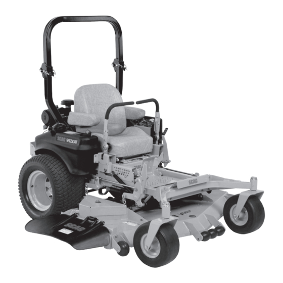
Scag Power Equipment WILDCAT STWC48V-25CV Operator's Manual
Scag power equipment lawn mower user manual
Hide thumbs
Also See for WILDCAT STWC48V-25CV:
- Illustrated parts manual (34 pages) ,
- Operator's manual (82 pages)
Table of Contents
Advertisement
Congratulations on owning a Scag mower! This manual contains the operating
instructions and safety information for your Scag mower. Reading this manual
can provide you with assistance in maintenance and adjustment procedures to
keep your mower performing to maximum efficiency. The specific models that
this book covers are listed on the inside cover. Before operating your machine,
please read all the information enclosed.
© 2008
Scag Power Equipment
Division of Metalcraft of Mayville, Inc.
OPERATOR'S
MANUAL
Wildcat
Models:
STWC48V-25CV
STWC48V-26KA-LC
STWC52V-25KA
STWC52V-26KA-LC
STWC61V-26KA-LC
STWC61V-27CV
PART NO. 03220 Rev. 3
PRINTED 9/2008
PRINTED IN USA
Advertisement
Chapters
Table of Contents

Related Manuals for Scag Power Equipment WILDCAT STWC48V-25CV


Summary of Contents for Scag Power Equipment WILDCAT STWC48V-25CV
- Page 1 The specific models that this book covers are listed on the inside cover. Before operating your machine, please read all the information enclosed. © 2008 Scag Power Equipment Division of Metalcraft of Mayville, Inc. OPERATOR’S MANUAL...
- Page 2 FAILURE TO FOLLOW SAFE OPERATING PRACTICES MAY RESULT • Read this manual completely as well as other manuals that came with your mower. • DO NOT operate on steep slopes. To check a slope, attempt to back up it (with the cutter deck down).
-
Page 3: Table Of Contents
Table of Contents SECTION 1 - GENERAL INFORMATION 1.1 INTRODUCTION ...1 1.2 DIRECTION REFERENCE ...1 1.3 SERvICING THE ENGINE AND DRIvE TRAIN COMPONENTS ...1 1.4 SYMBOLS ...2 SECTION 2 - SAFETY INFORMATION 2.1 INTRODUCTION ...3 2.2 SIGNAL WORDS ...3 2.3 BEFORE OPERATION CONSIDERATIONS ...3 2.4 OPERATION CONSIDERATIONS ...4 2.5 ROLL-OvER PROTECTION SYSTEM ...6 2.6 MAINTENANCE CONSIDERATIONS &... - Page 4 SECTION 6 - ADJUSTMENTS 6.1 PARKING BRAKE ADJUSTMENT ...22 6.2 TRAvEL ADJUSTMENTS ...22 6.3 THROTTLE CONTROL AND CHOKE ADJUSTMENTS ...24 6.4 BELT ADJUSTMENT ...24 6.5 BELT ALIGNMENT ...24 6.6 CUTTER DECK ADJUSTMENTS ...24 6.7 CUSTOM-CUT BAFFLE ADJUSTMENT ...26 6.8 ELECTRIC CLUTCH ADJUSTMENT ...28 SECTION 7 - MAINTENANCE 7.1 MAINTENANCE CHART - RECOMMENDED SERvICE INTERvALS ...29...
-
Page 5: General Information
All information is based upon product information available at the time of approval for printing. Scag Power Equipment reserves the right to make changes at any time without notice and without incurring any obligation. -
Page 6: Symbols
SYMBOLS SYMBOL DESCRIPTION Choke Parking Brake On/Start Off/Stop Falling Hazard Fast Continuously Variable - Linear Pinch Point 481039S Hour meter/Elapsed Operating Hours STT MODELS Seat must be installed under the seat hold down bracket during installation. Failure to secure the seat under the hold down bracket could result in serious injury or death in a roll over. -
Page 7: Safety Information
Section 2 INTRODUCTION Your mower is only as safe as the operator. Carelessness or operator error may result in serious bodily injury or death. Hazard control and accident prevention are dependent upon the awareness, concern, prudence, and proper training of the personnel involved in the operation, transport, maintenance and storage of the equipment. -
Page 8: Operation Considerations
If the operator(s) or mechanic(s) cannot read English or Spanish, it is the owner's responsibility to explain this material to them. DO NOT wear loose fitting clothing. Loose clothing, jewelry or long hair could get tangled in moving parts. Do not operate the machine wearing shorts; always wear adequate protective clothing including long pants. - Page 9 Section 2 To prevent tipping or loss of control, start and stop smoothly, avoid unnecessary turns and travel at reduced speed. When using any attachment, never direct the discharge of material toward bystanders or allow anyone near the machine while in operation. Before attempting to start the engine, with the operator in the seat, disengage power to the cutter deck, place the steering control levers in the neutral...
-
Page 10: Roll-Over Protection System
ROLL-OvER PROTECTION SYSTEM WARNING Reduce speed when turning, operating on slopes, slick or wet surfaces. Allow extra distance to stop. Stay off of slopes too steep for safe operation. To check a slope, attempt to back up it (with the cutter deck down). - Page 11 Section 2 Remove the hairpin cotter pins and remove the two (2) lock pins. See Figure 2-2. Lower the roll bar to the down position. To raise the roll bar, lift the bar to the upright position. Install the two (2) lock pins through the hole, secure with the two (2) hairpin cotter pins and tighten the tension knobs.
-
Page 12: Maintenance Considerations & Storage
MAINTENANCE CONSIDERATIONS & STORAGE Never make adjustments to the machine with the engine running unless specifically instructed to do so. If the engine is running, keep hands, feet, and clothing away from moving parts. Disengage drives, lower implement, set parking brake, stop engine and remove key or disconnect spark plug wire to prevent accidental starting of the engine when servicing or adjusting the machine. -
Page 13: Safety And Instructional Decals
Section 2 SAFETY AND INSTRUCTIONAL DECALS CAUT I ON Avoid injury from burns. Shut off engine before removing fuel tank cap. Molded in Fuel Tank START / DRI VE PROCEDURE W ARNI NG AVOI D SERI OUS I NJURY OR DEATH 483444 483444 INSTALL BELT COvER BEFORE... -
Page 14: Specifications
ENGINE General Type ...Heavy Duty Industrial/Commercial Gasoline Brand ...Kawasaki, Kohler Horsepower: Scag Model STWC48V-25CV ... 25hp (Spec #CV730-3112) Scag Model STWC52V-25KA ...25 hp (Spec. #FH721V-CS30-R) Scag Model STWC48V-26KA-LC, STWC52V-26KA-LC, STWC61V-26KA-LC ... 26 hp (Spec. #FD731D-BS05) Scag Model STWC61V-27CV ... 27 hp (Spec. #CV740-3110) Type ...4 Cycle Gasoline, Twin Cylinder, Vertical Shaft Cylinders ... -
Page 15: Cutter Deck
Section 3 Fuel Tanks ... Dual 4.5-Gallon Seamless Polyethylene Tanks with large opening and Fuel Cap Seat ... Padded, Thick Cushion with Extra Spring Support Travel Speed: Forward ...0-10 MPH Reverse ...0-5 MPH -NOTE- The machine will travel at 10 mph for transport purposes. For best cutting performance the forward travel speed should be adjusted depending upon the cutting conditions. -
Page 16: Operating Instructions
OPERATING INSTRUCTIONS CAUTION Do not attempt to operate this mower unless you have read this manual. Learn the location and purpose of all controls and instruments before you operate this mower. CONTROLS AND INSTRUMENT IDENTIFICATION Before operating the mower, familiarize yourself with all mower and engine controls. -
Page 17: Safety Interlock System
Section 4 Fuse Holders (Figure 4-1). Two 20-amp fuses protect the mower’s electrical system. To replace fuses, pull fuse out of the socket and install a new fuse. Left Steering Control (Figure 4-1). the mower's left wheel when traveling forward or reverse. -
Page 18: Starting The Engine
STARTING THE ENGINE CAUTION DO NOT USE STARTING FLUIDS. Use of starting fluids in the air intake system may be potentially explosive or cause a “runaway” engine condition that could result in engine damage and/or personal injury. Be sure the fuel shutoff valve, located behind the operator's seat, is completely open. -
Page 19: Engaging The Deck Drive (Cutter Blades)
Section 4 REvERSE TRAvEL CAUTION Disengage power to the mower before backing up. Do not mow in reverse unless absolutely necessary and then only after observation of the entire area behind the mower. CAUTION Before backing up, observe the rear for persons and obstructions. -
Page 20: Hillside Operation
HILLSIDE OPERATION WARNING DO NOT operate on steep slopes. To check a slope, attempt to back up it (with the cutter deck down). If the machine can back up the slope without the wheels slipping, reduce speed and use extreme caution. -
Page 21: Moving Mower With Engine Stopped
Section 4 4.11 MOvING MOWER WITH ENGINE STOPPED To “free-wheel” or move the mower around without the engine running, rotate the dump valve levers counter-clockwise open. See Figure 4-4. Disengage the parking brake and move the mower by hand. When the machine is in the desired position, engage the parking brake and rotate the levers clockwise until they stop (closed). -
Page 22: Adjusting The Steering Levers
Insert the lanyard pin into the cutting height index at the desired cutting height. Push forward on the deck lift foot lever, hold in place and pull back on the deck release lever. See Figure 4-6. Slowly release the foot pedal. -
Page 23: Troubleshooting Cutting Conditions
Section 5 TROUBLESHOOTING CUTTING CONDITIONS CONDITION STRINGERS - OCCASIONAL BLADES OF UNCUT GRASS Width of Deck SGB020 STREAKING - STRIPS OF UNCUT GRASS IN CUTTING PATH Width of Deck SGB018 STREAKING - STRIPS OF UNCUT GRASS BETWEEN CUTTING PATHS Width Width Deck Deck... - Page 24 TROUBLESHOOTING CUTTING CONDITIONS (CONT'D) CONDITION U N E v E N C U T O N F L AT GROUND - WAvY HIGH-LOW APPEARANCE, SCALLOPED CUT, OR ROUGH CONTOUR Width of Deck SGB020 UNEvEN CUT ON UNEvEN GROUND - WAvY APPEARANCE, HIGH-LOW SCALLOPED CUT, OR ROUGH CONTOUR Width of Deck...
- Page 25 Section 5 TROUBLESHOOTING CUTTING CONDITIONS (CONT'D) CONDITION SCALPING - BLADES HITTING DIRT OR CUTTING vERY CLOSE TO THE GROUND Width of Deck SGB022 STEP CUT - RIDGE IN CENTER OF CUTTING PATH Width of Deck SGB024 SLOPE CUT - SLOPING RIDGES ACROSS WIDTH OF CUTTING PATH Width of Deck...
-
Page 26: Adjustments
PARKING BRAKE ADJUSTMENT WARNING Do not operate the mower if the parking brake is not operable. Possible severe injury could result. The parking brake linkage should be adjusted whenever the parking brake lever is placed in the “ENGAGE” position and the parking brake will allow the mower to move. If the following procedures do not allow you to engage the parking brake properly, contact your Scag dealer for further brake adjustments. - Page 27 Section 6 NEUTRAL ADJUSTMENT Be sure the dump valve levers are in the run position and the steering control levers are in the neutral lock position. With an operator in the seat, start the engine and disengage the parking brake. Run the engine at full operating speed and check if the machine creeps forward or backwards.
-
Page 28: Throttle Control And Choke Adjustments
If at full speed the mower pulls left, it is an indication that the right wheel is turning faster than the left wheel. To adjust this condition, proceed as follows: A. Stop the machine and place the steering control levers in the neutral position. Loosen the lock nuts securing the ball joints at each end of the RH steering control rod. - Page 29 Section 6 CUTTER DECK PITCH The pitch of the cutter deck should be equal between the front and rear of the cutter deck for proper cutting performance. To check for proper deck pitch, be sure that the mower is on a flat, level surface and the tires are properly inflated.
-
Page 30: Custom-Cut Baffle Adjustment
Check the cutter deck cutting height by placing the lanyard pin in the 3" position on the cutting height index. Release the deck from the transport position and allow the deck to move to the 3" cutting height position. Check the measurement from the floor to the cutter blade tip. - Page 31 Section 6 Mounting Slot Figure 6-8. Mounting Slot Selected Figure 6-9. Custom-Cut Baffle Adjustment Mounting Hardware Location Slot “A” Hole 1 Height (inches) 3” 3-Position Custom-Cut Baffle Adjustment Custom-Cut Baffle Adjustment Mounting Hardware Location Slot “A” Hole 1 Hole 2 Height (inches) 3-3/4”...
-
Page 32: Electric Clutch Adjustment
ELECTRIC CLUTCH ADJUSTMENT The electric clutch serves two functions in the operation of the mower. In addition to starting and stopping the power flow to the cutter blades, the clutch also acts as a brake to assist in stopping blade rotation when the PTO is switched off or the operator presence circuit is interrupted. -
Page 33: Maintenance
Section 7 MAINTENANCE CHART - RECOMMENDED SERvICE INTERvALS HOURS BREAK-IN 100 200 500 (FIRST 10) * Perform these maintenance procedures more frequently under extreme dusty or dirty conditions MAINTENANCE PROCEDURE Check all hardware for tightness Check hydraulic oil level C h e c k a l l b e l t s f o r p r o p e r alignment Change engine oil and filter Check coolant level... -
Page 34: Lubrication
MAINTENANCE CHART - RECOMMENDED SERvICE INTERvALS (CONT'D) HOURS BREAK-IN (FIRST 10) LUBRICATION GREASE FITTING LUBRICATION CHART (SEE FIGURE 7-1) LOCATION 1 Caster Wheel Pivot * 2 Caster Wheel Bearings 3 Brake Actuator 4 Cutter Deck Bellcranks 5 Cutter Deck Pusharms 6 Control Pivot 6 Cutter Deck Spindle 7 Brake Handle... -
Page 35: Lubrication Fitting Points
Section 7 GREASE FITTING LUBRICATION Lubricant Interval Figure 7-1. Lubrication Fitting Points Lithium MP White Grease 2125 (40 Hours/Weekly) Chassis Grease (100 Hours/Bi-monthly) Chassis Grease (200 Hours/Monthly) Chassis Grease (500 Hours/Yearly) -
Page 36: Hydraulic System
HYDRAULIC SYSTEM A. CHECKING HYDRAULIC OIL LEvEL The hydraulic oil level should be checked after the first 10 hours of operation. Thereafter, check the oil after every 200 hours of machine operation or monthly, whichever occurs first. - IMPORTANT - If the oil level is consistently low, check for leaks and correct immediately. -
Page 37: Engine Oil
Section 7 C. CHANGING HYDRAULIC OIL FILTER ELEMENT The hydraulic oil filter should be changed after every 500 hours of operation or annually, whichever occurs first. Remove the oil filter element and properly discard it. See Figure 7-3. Fill the new filter with clean oil and install the filter. -
Page 38: Engine Air Cleaner
Remove the machine from the truck or trailer and fuel on the ground. If this is not possible, then refuel the machine with a portable container, rather than from a gasoline dispenser nozzle. Keep the nozzle in contact with the rim of fuel tank or container opening at all times until fueling is complete. -
Page 39: Battery
Section 7 BATTERY WARNING Lead-acid batteries produce flammable and explosive gases. To avoid personal injury when checking, testing or charging batteries, DO NOT use smoking materials near batteries. Keep arcs, sparks and flames away from batteries. Provide proper ventilation and wear safety glasses. WARNING Battery posts, terminals, and related accessories contain lead and lead compounds, chemicals... -
Page 40: Drive Belts
DRIvE BELTS All drive belts are spring-loaded and self-tensioning, however after the first 2, 4, 8 and 10 hours of operation, the belts should be checked for proper alignment and wear. Thereafter, check the belts after every 40 hours of operation or weekly, whichever occurs first. -
Page 41: Tires
Section 7 - NOTe - The front of the machine will have to be raised slightly to remove the blade bolt from the cutter spindle. To install the new cutter blade, put the flat washer onto the blade bolt and slide the bolt into the hole in the cutter blade. -
Page 42: Body, Deck, And Upholstery
Replace the radiator cap. Push down on the cap and turn clockwise until it stops. - NOTe - The cooling system should be flushed and the coolant replaced every 500 hours of operation or annually. See your Scag dealer for proper coolant replacement. - Page 43 Section 7 NOTES...
-
Page 44: Illustrated Parts List
ILLUSTRATED PARTS LIST SCAG APPROvED ATTACHMENTS AND ACCESSORIES Attachments and accessories manufactured by companies other than Scag Power Equipment are not approved for use on this machine. Scag approved attachments and accessories: • GC-STC-V (48" & 52"), GC-STWC-61V (p/n 9057, p/n 9058) •... -
Page 45: Notes
Section 8 ILLUSTRATED PARTS LIST NOTES... -
Page 46: 48V & 52V Cutter Decks
6 7 8 5 25 * 52" cutter deck has a notch for anti-scalp roller 48v & 52v CUTTER DECKS Section 8 64 60 62 61 59 58 66 63 STC 2006 CD4852 Rev.1... - Page 47 Section 8 Ref. Part No. Description 461854 Cutter Deck Velocity Plus 461858 Cutter Deck Velocity Plus 43686 Boss, Spring Anchor 04019-04 Nut, 3/8-16 Serrated Flange 481625-01 Wing Nut, 3/8-16 481632 Anti-Scalp Wheel 04003-26 Bolt, Carriage 3/8-16 x 4” 422478 Bracket, Anti-Scalp Wheel 04017-27 Bolt, Serrated Flange 3/8-16 x 1”...
-
Page 48: 61V Cutter Deck
6 7 8 5 25 61v CUTTER DECK "A" "A" 2 80 Section 8 64 60 62 61 59 58 66 63 STWC 2006 CD61... - Page 49 Section 8 Ref. Part No. Description 461862 Cutter Deck Velocity Plus 43687 Boss, Spring Anchor 424371 Bracket, LH Spring Anchor 61V 481625-01 Wing Nut, 3/8-16 481632 Anti-Scalp Wheel 04003-26 Bolt, Carriage 3/8-16 x 4” 422478 Bracket, Anti-Scalp Wheel 04017-27 Bolt, Serr. Flng. 3/8-16 x 1” 04043-06 Flatwasher, 5/8”...
-
Page 50: Cutter Deck Controls
CUTTER DECK CONTROLS CUTTER DECK Section 8 STC 2006 CDC... - Page 51 Section 8 Ref. Part No. Description 482624 Rod, Deck Lift Linkage 04020-28 Nut, Jam 1/2-20 LH Thread 481766 Rod End, 1/2-20 Female LH Thread 04050-10 Retaining Ring, 1/2” Ext. “E” 483062 Slide, Deck Height Adjust 43487 Pin, Deck Lift 423463 Bracket, Cutting Height Adjustment 04001-22 Bolt, Hex Hd.
-
Page 52: Sheet Metal Components
SHEET METAL COMPONENTS 18 19 Section 8 26hp Kawasaki 7 8 20 STWC 2008 SMC... - Page 53 Section 8 Ref. Part No. Description 461918 Main Frame Assembly w/Decals 04001-73 Bolt, Hex Hd. 5/16-18 x 3-3/4” 482938 Back Cover 04019-04 Nut, Serr. Flng. 3/8-16 461989 Plate, Seat Mounting 482939 Cushion Cover 43462 Pin Retainer, Spring 481389 Spring Battery (not available through Scag) 423571 Battery Cover 482553...
-
Page 54: Stwc Roll-Over Protection System
Section 8 STWC ROLL-OvER PROTECTION SYSTEM STWC 2007 ROPS... - Page 55 Section 8 STWC ROLL-OvER PROTECTION SYSTEM Ref. Part No. Description 461956 STWC Foldable ROPS 04001-145 Bolt, Hex Hd. 1/2-13 x 3-1/2” 04021-19 Nut, Center Lock 1/2-13 483412 Retractable Seat Belt 04040-13 Flatwasher, 1/2 (.562 x 1.375 x .109") 481625-03 Thumb Screw, 5/16-18 NC x 3/4” 04062-06 Hair Pin, Cotter 483262...
-
Page 56: Drive System Components
DRIvE SYSTEM COMPONENTS Section 8 STWC 2008 DSC... - Page 57 Section 8 Ref. Part No. Description 04021-09 Nut, Elastic Stop 3/8-16 04019-04 Nut, Serr. Flng. 3/8-16 483087 Spring, Pump Idler 43286 Spacer 04001-22 Bolt, Hex Hd. 3/8-16 x 2-3/4” 461603 Idler Arm Assy., Pump Drive 04063-14 Key, 5 x 5 x 25mm 483172 Belt, Transmission 483415...
-
Page 58: Engine And Attaching Parts
Section 8 ENGINE AND ATTACHING PARTS SC 2004 EAPKA... - Page 59 Section 8 ENGINE AND ATTACHING PARTS Ref. Part No. Description 483685 Engine, Kohler Command 25hp 482900 Engine, 27HP Kohler 482827 Engine, 25HP Kawasaki 483126 Engine, 26HP Kawasaki Liquid-Cooled 423770 Bumper, Rear 41031 Weight, Rear (Shield) 61V Only 424107 Shield, Rear 52V Only 04019-04 Nut, Serr.
-
Page 60: Steering Components
STEERING COMPONENTS 29, 29A Section 8 To Pump STC 2006 SSC REV 1... - Page 61 Section 8 Ref. Part No. Description 482340 Grip, Control Lever 461914 Handle Bar, LH (Incl. item 1) 461923 Handle Bar, RH (Incl. item 1) 04001-09 Bolt, Hex Hd. 5/16-18 x 1” 04030-03 Lockwasher, 5/16” 483269 Knob 04040-15 Flatwasher, 5/16 (.375 x .875 x .083") 04060-01 Roll Pin, Spring 5/32 x 3/4”...
-
Page 62: Brake Components
40 16 17 35 31 11 3 BRAKE COMPONENTS Section 8 15 14 13 12 STC 2002 BSC... - Page 63 Section 8 Ref. Part No. Description 04019-06 Nut, Serr. Flng. 1/2-13 48807 Spring 04001-08 Bolt, Hex Hd. 5/16-18 x 3/4” 04001-163 Bolt, Hex Hd. 1/2-13 x 3-3/4” 04001-52 Bolt, Hex Hd. 1/2-13 x 2-1/2” 04021-19 Nut, 1/2-13 Center Lock 483190 Wheel Motor, Hydro-Gear 04063-25 Key, Woodruff 5/16 x 1”...
-
Page 64: Fuel And Hydraulic System
FUEL AND HYDRAULIC SYSTEM 3 55 45 46 18 19 33 47 48 ENGINE 35 32 54 48 47 49 Section 8 20 19 STWC 2005 FHS... - Page 65 Section 8 FUEL AND HYDRAULIC SYSTEM Ref. Part No. Description 482643 Pump, BDP-10A-316 (LH) 482644 Pump, BDP-10A-419 (RH) 482266-01 Elbow, 90 Degree 9/16" O-Ring x 3/8" Hose 48572-02 Fitting, 1/2” JIC x 5/8" O-Ring 48811 Hose, 3/8" Pushlock (Specify length) 482573 Bushing 482574...
-
Page 66: Electrical System - Kohler & Kawasaki Air-Cooled
ELECTRICAL SYSTEM - KOHLER & KAWASAKI AIR-COOLED Section 8 STWC 2008 ESKH... - Page 67 Section 8 ELECTRICAL SYSTEM - KOHLER & KAWASAKI AIR-COOLED Ref. Part No. Description 483355 Hourmeter 48298 Fuse, 20 Amp 483366 Key, Ignition 462069 Key Assembly w/Fob 48017-04 Nut, Hex 5/8-32 48017-03 Lockwasher, 5/8” Internal 461660 Electric PTO Clutch GT3.5 48798 Switch, Ignition 483957 Switch, PTO...
-
Page 68: Electrical System - 26Hp Kawasaki Liquid-Cooled
ELECTRICAL SYSTEM - 26HP KAWASAKI LIqUID-COOLED Section 8 STWC 2008 ESKALC... - Page 69 Section 8 ELECTRICAL SYSTEM 26HP KAWASAKI LIqUID-COOLED Ref. Part No. Description 483355 Hourmeter 48298 Fuse, 20 amp 483366 Key, Ignition 462069 Key Assembly w/Fob 48017-04 Nut, Hex 5/8-32 48017-03 Lockwasher, 5/8” Internal 461660 Electric PTO Clutch GT3.5 48798 Switch, Ignition 483957 Switch, PTO 48788...
-
Page 70: Hydraulic Pump Assembly
PORT "A" SIDE HYDRAULIC PUMP ASSEMBLY PORT "B" SIDE Section 8... - Page 71 Section 8 Ref. Part No. Description HG 70516 Housing Kit HG 70573 End Cap Kit HG 50641 Straight Headless Pin HG 50969 Hex Flng. Bolt, M8-1.25 x 60mm HG 51232 Housing O-Ring HG 2513027 Charge Pump Kit HG 50273 Gerotor Assembly HG 9004101-1340 O-Ring HG 50095...
-
Page 72: Replacement Decals And Information Plates
REPLACEMENT DECALS AND INFORMATION PLATES FORWARD REvERSE 482100 WARNING INSTALL BELT COvER BEFORE OPERATING MACHINE READ OPERATOR'S MANUAL MANUFACTURED UNDER ONE OR MORE OF THE FOLLOWING PATENTS: 4,487,006 4,885,903 4,920,733 4,967,543 4,991,382 4,998,948 5,042,239 5,117,617 5,133,176 5,826,416 5,832,708 5,865,018 6,192,666 6,766,633 6,892,519 6,996,962... - Page 73 Section 8 REPLACEMENT DECALS AND INFORMATION PLATES Ref. Part No. Description 483407 Decal, Danger-Spinning Blades 483406 Decal, Warning-Rotating Blades 483199 Decal, 48V 483200 Decal, 52V 483201 Decal, 61V 483158 Decal, ROPS 483044 Decal, Patents 482100 Decal, Traction Control 481971 Decal, Heavy Duty Commercial 48404 Decal, Metalcraft - Made in USA 483402...
-
Page 74: Electrical Schematic - Kohler & Kawasaki Air-Cooled
ELECTRICAL SCHEMATIC - KOHLER & KAWASAKI AIR-COOLED KAWASAKI ADAPTER HARNESS WHITE MAGNETO RED W/YEL STRIPE FUEL SOLENOID YELLOW RECTIFIER GRN W/WHT STRIPE SOLENOID MAIN HARNESS KOHLER ADAPTER HARNESS GRN W/WHT STRIPE WHITE ENGINE PLUG YELLOW SOLENOID "B+" MAIN HARNESS BLACK BLACK BLACK GROUND... -
Page 75: Electrical Schematic - 26Hp Kawasaki Liquid-Cooled
Section 8 ELECTRICAL SCHEMATIC - 26HP KAWASAKI LIqUID-COOLED SWITCH BLACK BLACK BLACK GROUND CLUTCH (600V 2A) HOURMETER MAIN HARNESS WATER TEMP GAUGE SWITCH 20 AMP FUSES DIODE ENGINE ADAPTER HARNESS ADAPTER HARNESS WHITE YELLOW GRN W/WHT STRIPE WHITE W/BLACK STRIPE RED W/YEL STRIPE RELAY BRAKE... - Page 76 Cutter decks are warranted against cracking for a period of three (3) years. (Parts and labor 1st and 2nd year; Parts only 3rd year.) The repair or replacement of the cutter deck will be at the option of Scag Power Equipment. We reserve the right to request components for evaluation.
- Page 77 (Piezas y mano de obra) (La garantía de dos años no incluye las conexiones, mangueras, las correas de transmisión). La reparación o el reemplazo de la bomba hidráulica o el motor hidráulico estarán sujetos a discreción de Scag Power Equipment.
-
Page 78: Tapicería Y Plataforma Cuerpo
pintura. protección darle para cortacésped Encere distribuidor disponible Scag dañadas metal superficies asiento. limpiar limpiador jabón suave eléctricos. componentes presión. limpiadores limpiadores fría agua corte. cortacésped lave uso, cada comprimido. aire motor; está mientras equipo parte PrecaUciÓn TaPicería PlaTaForma cerrojo. radiador desechos desechos. -
Page 79: Refrigeración De Sistema
agua. manguera comprimido aire desechos desechos Criba 7-9. 7-9. Figura ella tire desechos criba comprimido. aire usar gafas siempre personales, PrecaUciÓn radiador. criba limpie retire operación, deSecHoS criba refrigerante. reemplazo sobre información para Scag Consulte año. cada operación cada reemplazado debe purgado debe... -
Page 80: Llantas 7.10
motrices macizas Llantas diariamente. cada después llantas presiones lbs-pie. apriete giro Evite corte. superior cuchilla perno hexagonal corte. perno cuchilla perno espaciador superior. parte hacia aleta instale cuchilla NOTA cuchilla Reemplazo 390S0160 HEXAGONAL PERNO CORTE CUCHILLA CORTE CUCHILLA ESPACIADOR HEXAGONAL CABEZA TUERCA PERNO... -
Page 81: Corte Cuchise
filo. mantener para corte superior parte afile Sólo 7-6. Figura bisel mismo corte 7-6. Figura ancho más cuchillas NOTA cuchilla. quemar puede esmeriladora, cuchilla. afilar para lima NOTA cUcHillaS tirar cuchilla motor desgaste causa cortacésped velocidad disminuye sino produce sólo desafiladas Cortar cuchillas. -
Page 82: Batería
celdas. cubre electrolito asegúrese cortacésped batería quite posible, cargador. antes entibie batería Permita estallar Puede congelada. batería cargador necesitará batería, puede alternador tiempo, completamente descargado batería. carga mantener para motor alternador normales específicas. para batería cargador manual baTería vómito. induzcan líquidos interno, contacto... -
Page 83: Motor Del Aire De Filtro
seguros. bien cerrar aire filtro tapa reemplace motor. fabricante recomienda pre-filtro aire filtro reemplace inspecciónelo. aire costado. retire aire filtro conjunto cubierta fijan seguros motor. daños prevenir veces elemento verificar puede polvo, mucho NOTA necesario. elemento ocurra semanas, cada cada después aire filtro... -
Page 84: Motor Del Aceite
para aprobado recipiente ignición. otras pipas puros, cigarrillos, vapores inflamable extremadamente gasolina gasolina. manipular propiedad, daños personales motor. combustible E85. máximo mínimo octanaje libre limpia, gasolina demasiado. cuello debajo pulgada día cada inicio combustible combUSTible TanqUe rellenar. combustible tapa quitar antes enfríe permita... -
Page 85: Hidráulico Sistema
página hidráulico” filtro elemento “Cambio explica como filtro hidráulico, aceite depósito NOTA ajustado. esté drenaje tapón drenaje Tapón hidráulico aceite STC2001HODP HIDRÁULICO HIDRÁULICO ACEITE ACEITE DRENAJE TAPÓN deséchelo recipiente fluido 7-3. Figura filtro. base drenaje fondo tapón depósito llenado adelante. hacia asiento Incline... - Page 86 conexión horas/anualmente) chasis horas/mensualmente) chasis meses) horas/cada chasis horas/semanalmente) 2125 litio blanca lubricación LUBRICACIÓN GRASA puntos Lubricación (500 Grasa (200 Grasa (100 Grasa Grasa Intervalo CONEXIONES 7-1. Figura Sección...
-
Page 87: Lubricación 7.2
número especial herramienta usar Quite libre. rueda extensión superior instale 482028-01 parte número industriales Shell Conoco servicio estaciones Exxon chasis 2125 litio blanca chasis chasis chasis chasis chasis chasis UbicacioneS lUbricanTe nº 7-1) FiGUra 7.11 párrafo Scag distribuidor Consulte párrafo aceite párrafo 20W50. - Page 88 suciedad polvo extremas condiciones párrafo aire párrafo párrafo párrafo cables párrafo párrafo filtro 7.11 párrafo párrafo párrafo 7.10 párrafo párrafo párrafo 7.12 párrafo párrafo motor párrafo hidráulicas. mangueras verificar cuidado mucho Tenga 7.11 párrafo párrafo filtro párrafo alineación párrafo hidráulico esté...
-
Page 89: Personalizado Corte De Deflector Del Ajuste
posiciones 4-1/2” 4” Orificio Orificio 5-1/4” 4-3/4” Orificio Orificio montaje personalizado posiciones 4” Orificio montaje Sección personalizado corte deflector 3-1/2” Orificio 4-1/4” 3-3/4” Orificio Orificio accesorios Ubicación seleccionada corte deflector Ajuste personalizado corte deflector 3-1/2” 3” (pulgadas) Orificio Orificio1 accesorios Ubicación montaje personalizado... - Page 90 lb/pie. torque Apriete montaje. accesorios 6-9. Figura personalizado corte corte. plataforma acuerdo variar puede ubicación referencia. para usados accesorios NOTA corte. plataforma deflector aseguran posición corte corte. plataforma “soplos” hojas) (recogida otoño corte ó 4-3/4” ajuste deflector 6-9). Figura (Vea 5-1/4”...
-
Page 91: Corte De Plataforma La De Ajustes
posición corte plataforma personalizado: corte deflector plataforma “soplos” reducirá (recogida otoño corte mejorará deflector colocación corte. dentro soldado frontal deflector inferior conjunto usando instala Figuras (Vea fábrica) (ajuste césped. tipos todos corte combinación adecuada personalizado corte deflector propósito cortes para usar puede plataforma... - Page 92 6-6. Figura altura control varilla ambos contratuercas posición corte plataforma infladas estén llantas nivel esté cortacésped asegúrese apropiada altura verificar señalada altura corte misma realiza corte plataforma CORTE PLATAFORMA disparejo. inferior Plus Velocity plataformas superior borde desde medidas Todas anteriormente. procedimientos explicó...
-
Page 93: Correa La De Alineación
6-4. Figura plataforma nivel ajuste corte plataforma frontal izquierdo debe corte plataforma nivel medidas iguales. deben máquina. izquierdo lado piso plataforma inferior parte desde Luego piso. hasta corte plataforma parte desde distancia verifique derecho lado usará. común fijada esté corte plataforma infladas estén... - Page 94 arriba. neutral, neutral. ajuste haga atrás, hacia lentamente avanza máquina explicó como ajuste realizar NOTA 6-3. Figura rueda velocidad disminuyendo bomba menos golpee control causará Esto bloqueo. tuercas estirar para control varilla Gire dirección control varilla rótula juntas aseguran bloqueo Afloje neutral.
-
Page 95: Desplazamiento De Ajustes
25). página alineación, adelante. hacia desplazarse otro cortacésped adelante hacia completamente están dirección control 25). página neutral, (Ajuste adelante hacia arrastra máquina están dirección control alineación neutrales ajustes realizar DESPLAzAMIENTO freno varilla Ajuste 390S0153-1 AQUÍ AFLOJE freno Ajuste 6-1. FRENO MANGO autorizado distribuidor... - Page 96 autorizado SCAG distribuidor Consulte autorizado SCAG distribuidor Consulte autorizado SCAG distribuidor Consulte autorizado SCAG distribuidor Consulte autorizado SCAG distribuidor Consulte cuchilla Reemplace nivel inclinación Ajuste seque césped Corte terreno condiciones ajustarse para velocidad Disminuya corte dirección cambiar corte plataforma altura aumentar terreno, velocidad...
- Page 97 corrija nivel Verifique autorizado SCAG distribuidor Consulte llantas presión ajuste Revise llantas presión ajuste Revise corte dirección cambiar corte plataforma aumentar terreno, velocidad reducir tener puede cuchilla autorizado SCAG distribuidor Consulte autorizado SCAG distribuidor Consulte nivel inclinación Ajuste plataforma abajo parte Limpie terreno...
- Page 98 pase cada traslape Aumente cuchillas Reemplace seque césped Corte terreno condiciones ajustarse para velocidad Disminuya plataforma abajo parte Limpie correa tensión Ajuste máxima motor Opere cuchillas cuchillas correa tensión Ajuste plataforma abajo parte Limpie cuchillas seque césped Corte terreno condiciones ajustarse para velocidad...
- Page 99 cortacésped. remolque conectado remolque cero detenerse. distancia permita lentamente control. tracción pérdida causar puede equipo peso cuestas. remolque Kg). (113 Peso remolcado. equipo para para fabricante recomendaciones punto remolcado equipo remolcar. para diseñado enganche tenga máquina remolcado. personas otras niños oPCIoNAl) (ACCESoRIo REmolqUE...
- Page 100 comodidad. tenga verificar para atrás hacia dirección palancas ambas mueva operador posición deseada. posición asiento PAlANCAS plataforma liberación Palanca 2006 PLATAFORMA LIBERACIÓN PALANCA 4-5. Figura deseada. altura ajustar para ayuda como altura ubicada plataforma altura pedal. lentamente Libere plataforma. liberación tire posición manténgala...
- Page 101 (corte corto demasiado césped demasiado seco esté cuando lanzados. objetos debido daños posibilidad reducir lejos descarga dirija obstáculos, corte Cuándo césped. recortes minimizar para calles aceras descarga Dirija mismo. sobre encuentre objeto cualquier cortado césped desviar para baja más posición debe quitarse debe...
-
Page 102: Operación La De
caliente. está para comprimido aire motor. agua operación. caliente IMPORTANTE eléctricos. sobre chorro dirija presión uso. cada después cortacésped oPERACIÓN quite posición encendido estacionamiento. velocidad hasta motor velocidad corte. cuchillas dirección control palancas máquina estacione plana superficie cortacésped EStACIoNAmIENto infladas. correctamente llantas dirección. -
Page 103: De Transmisión La De
Figura accionada. posición panel ubicado amarillo, tirando plataforma transmisión plataforma. accionar motor moderada velocidad — eléctrico embrague vida velocidad alta plataforma accionar trate máxima. cerca aceleración CoRtE) (CUCHIllAS tRANSmISIÓN freno accione bloqueo, neutral asas coloque estacionado, neutral. posición vuelvan dirección permita reversa, desplazamiento... -
Page 104: Terreno El En Desplazamiento
nuevamente dirección control tire adelante, hacia desplazamiento palancas tire disminuirla, dirección control palancas aumentar Para velocidad. será empujen adelante más Cuanto adelante hacia dirección palancas empuje neutral posición sacándolas palancas lleve estacionamiento, cortacésped, adelante hacia AdElANtE HACIA dESPlAzAmIENto antes controles cómodo hasta cortacésped... -
Page 105: Seguridad De Bloqueo De Econtroles De
propiedad. causar terceros usted lesiones puede hacerlo interruptor; ponga desconecte defectuosamente. funcionando desconectado sistema cortacésped AdVERtENCIA accionado. freno accionadas corte cuchillas distinta posición dirección palancas asiento deja operador apaga bloqueo sistema asiento. neutral posición dirección accionado, esté estacionamiento desconectada, esté plataforma menos arranque... -
Page 106: Identificación
2007 ASIENTO SUJECIÓN SEGURO LIBERADOR HORÓMETRO CINTUR SEGURIDAD ÓN CORTE PLATAFORMA LIBERACIÓN PALANCA DIRECCIÓN DERECHO CONTROL CORTE ALTURA AJUSTE automáticamente. Reinicia hasta destellando continuará establecida antes horas destellar empezará mantenimiento hidráulico. sistema cambios motor mantenimiento recordatorios fijado funcionando. cuando opera Sólo motor. -
Page 107: Productividad
giros. traslape para estimado tabla día. Scag 23,7 20,2 61” 52” 1150# 1100# 54” 54” 66” 66” 62” 53” 73,5” 64,5 46,5” 46,5” 83” 80” cuartos 2-1/2 capacidad ...Nylon; micras (spin-on) roscado ...Tipo Ogura pesado servicio Embrague apretado auto ajustado, Auto Kevlar. -
Page 108: Sistema
radial borde capas, cuatro neumática, radial borde capas, cuatro neumática, cónicos rodillos rodamientos motrices ruedas ambas ejes frenos conectado palanca amortiguadores rueda dedos, punta accionado torque alto fundido hierro Hydro-Gear™ motor operación desplazamiento descarga válvulas cc/rev. torque alto fundido hierro motores variable desplazamiento... - Page 109 483300 Decals Safety &STWC 2007 482709 483023 483425 482291 483411 483397 483406 481568 483407 483402 SEgurIdAd Sección...
-
Page 110: Calcomanías
InStructIvAS cALcoMAníAS herramientas protección ropa desconectarlo conectarlo Desenchufe llamas. chispas bien abierta área baterías techo. llamas cerca combustible almacenamiento durante combustible abierto. fuego cerca máquina almacenarlo. antes enfríe motor gangrena. producirse puede horas pocas unas dentro retirado debe piel, inyecta fluido Scag. - Page 111 seguridad cinturón Inspección CORREA TEJIDO INSPECCIONE SEGURO HEBILLAS INSPECCIONE 2-3. Figura agrietada. dañada deformada gastada, excesivamente placa determine funcionamiento verificar para seguro seguridad. cinturón reemplace condiciones, estas existen haberse puede correas estas física suciedad, lleno decolorado está áreas estas correas extrema.
- Page 112 sujeción. soportes cinturón Quite 2-2. Figura perillas apriete horquillas pasadores asegúrelos través bloqueo pines vertical. barra suba vuelco, contra barra baja. posición vuelco contra 2-2. Figura bloqueo. horquillas chaveta pasadores derecho. izquierdo lado barras perilla afloje vuelco, contra barra contacto entre encuentre objeto...
-
Page 113: Sistema
normales condiciones bajo estabilidad buena tener para diseñado hacia manejando baje rampa más estar debe rampa ancha. bien rampa trailers descargar cargar opere entrenamiento personal control. tracción pérdida causar equipo peso cuestas. remolque paradas arranques giros suavemente, máquina derrumba. borde encima pasa rueda... - Page 114 causar puede contacto móviles. cuchillas lejos pies manos muerte. daño causar pueden carbono contienen peligrosos escape apropiada. ventilación edificio dentro motor PELIgro causar para como calientes suficientemente estar pueden zonas Estas detenerlo. inmediatamente funcionando, mientras silenciador motor PrEcAucIón máquina. operar reiniciar debe daño...
- Page 115 rápidamente. equipo sepa controles todos función oPErAcIón conSIdErAcIonES máquina. antes estado buen estén líneas mangueras todas hidráulicas conexiones todas correctamente estén cuchilla pernos frecuentes intervalos completamente opcionales desmenuzadora césped recogedor baja instalada lateral descarga tolva equipo. requisitos normas informarse para locales autoridades Contacte...
-
Page 116: Palabras
arrojados recogidos pudieran todos cortada debe juguete. jueguen suban niños área. ingresa niño apague atento Esté operador. responsable adulto atento área fuera niños Mantenga estén personas otras niños apropiadas. máquina esta operen adultos cortacésped. este operen niños PrEvIAS conSIdErAcIonES correcta operación prácticas todos... -
Page 117: Símbolos 1.4
operador manual Desconectar cortante Elemento Conectar cortante Elemento básico Símbolo cortante Elemento lanzados objetos Peligro polea resorte Tensión giratoria Cuchilla Transmisión dEScrIPcIón Sección curiosos muerte puede debajo asiento soporte debe asiento Marca operación Lineal Lento Aceite SíMBoLo alejados Mantenga lanzados objetos Peligro volcadura. -
Page 118: Referencia
puede garantía período durante estos realizado autorizado componente. fabricante autorizado local agente encontrar Scag contactar importante limitada, durante componentes estos servicio servicio rutina mantenimiento proporcionan sólo manual; están cambios, cajas hidráulicas, motor, reparación servicio trEn Motor adelante. dirección cara posición sentado está... - Page 119 SECCIÓN dESpuÉS ...70 ...69 ...68 ...66 ...64 ...62 ...60 ...58 ...56 ...54 ...52 ...50 ...48 ...46 ...44 ...42 ...40 ACCESSORIES...39 ...39 ...41 ...40 ...39 ...38 ...38 bATERíA...37 ...36 ...35 ...35 ...34 ...32 ...31 RECOMENdAdOS ...31 ...28 ...26 ...26 ...26 ...26 ESTRANGuLACIÓN ...24 ESTACIONAMIENTO...24...
- Page 120 ...20 ...19 ...19 ...18 ...18 ...18 ...17 ...17 ...17 ...16 CORTE) ...15 ...15 ...15 ...14 ...13 ...13 ...12 dIMENSIONES...12 ...12 ...12 ...11 ...11 ...11 ...11 ...10 ...9 ...6 ...4 ...3 ...3 ...3 ...3 ...2 ...1 TRANSMISIÓN ...1 ...1 ...1 OpCIONAL) ENGANCHE dIRECCIÓN CÉSpEd...
- Page 121 aparece completo D9399999 D9300001 D9299999 D9200001 D9199999 D9100001 D7299999 D7200001 D7199999 D7100001 D7099999 D7000001 D6999999 D6900001 E4499999 E4400001 E4399999 E4300001 para: ilustradas partes EqUIPO. ALMACENAMIENTO RELACIONADO PERSONAL CONOCIMIENTO, DEPENDEN OPERADOR! COMO debe persona móviles. limpiar. quite máquina detenga tolva control tracción OSHA.
- Page 122 E.E.U.U. IMPRESO 9/2008 IMPRESO Rev.3 03220 Nº PARTE Antes específicos mantener ayudar seguridad manual Este STWC61V-27CV STWC61V-26KA-LC STWC52V-26KA-LC STWC52V-25KA STWC48V-26KA-LC STWC48V-25CV Wildcat OPERADOR MANUAL Inc. incluida. información interior. cubierta indicados modelos eficiencia. máxima ajuste procedimientos puede manual este lectura información operación Scag! cortacésped...