Table of Contents
Advertisement
Quick Links
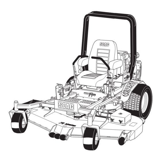
MODEL STT-31BSD
THIS MANUAL CONTAINS THE OPERATING
INSTRUCTIONS AND SAFETY INFORMA-
TION FOR YOUR SCAG MOWER. READING
THIS MANUAL CAN PROVIDE YOU WITH
ASSISTANCE IN MAINTENANCE AND AD-
JUSTMENT PROCEDURES TO KEEP YOUR
MOWER PERFORMING TO MAXIMUM EFFI-
CIENCY. THE SPECIFIC MODELS THAT THIS
BOOK COVERS ARE CONTAINED ON THE
INSIDE COVER. BEFORE OPERATING YOUR
MACHINE, PLEASE READ ALL THE INFOR-
MATION ENCLOSED.
© 2004
SCAG POWER EQUIPMENT
DIVISION OF METALCRAFT OF MAYVILLE, INC.
PART NO. 03153
PRINTED 10/04
PRINTED IN USA
Advertisement
Table of Contents

Related Manuals for Scag Power Equipment STT-31BSD


Summary of Contents for Scag Power Equipment STT-31BSD
- Page 1 MODEL STT-31BSD THIS MANUAL CONTAINS THE OPERATING INSTRUCTIONS AND SAFETY INFORMA- TION FOR YOUR SCAG MOWER. READING THIS MANUAL CAN PROVIDE YOU WITH ASSISTANCE IN MAINTENANCE AND AD- JUSTMENT PROCEDURES TO KEEP YOUR MOWER PERFORMING TO MAXIMUM EFFI- CIENCY. THE SPECIFIC MODELS THAT THIS BOOK COVERS ARE CONTAINED ON THE INSIDE COVER.
- Page 2 This manual covers the operating instructions STT-31BSD with a serial number of A7400001 to A7499999 SMST-61A with a serial number of A7500001 to A7599999...
-
Page 3: Table Of Contents
TABLE OF CONTENTS SUBJECT Section 1 - General Information Introduction ...1 Directional Reference ...1 Servicing the Engine and Drive Train Components ...1 Section 2 - Safety Information Symbols ... 2-3 Introduction ...4 Signal Words ...4 Before Operation Considerations ...4 Operation Considerations ...5 Roll Over Protection System ...6 Maintenance Considerations ...8 Safety and Instructional Decals ...9... -
Page 4: Subject Page
Radiator, Coolers & Engine Brackets...50-51 Brake & Steering Components..52-53 Fuel & Hydraulic System ... 54-55 Electrical System ... 56-57 Hydraulic Pump Assembly - BDP-21L ... 58-59 Wire Harness, STT-31BSD ... 60 Replacement Decals ... 61-62 Warranty Statement ... Inside Back Cover PAGE... -
Page 5: Section 1 - General Information
Figure 1-1 Tractor Serial Number Plate Location USE ONLY SCAG APPROVED ATTACHMENTS AND ACCESSORIES. Attachments and accessories manufactured by companies other than Scag Power Equipment are not approved for use on this machine. GENERAL INFORMATION Scag approved attachments and accessories:... -
Page 6: Symbols
ISO Symbols SYMBOL DESCRIPTION Choke Parking Brake On/Start Off/Stop CE Mark SYMBOL DESCRIPTION Transmission Spinning Blade 48071S Spring Tension on Idler WARNING Falling Hazard FALLING HAZARD USE ONLY SCAG APPROVED RIDING ATTACHMENTS SEE OPERATOR'S MANUAL 481109... -
Page 7: Symbols
SYMBOL DESCRIPTION Fast Continuously Variable - Linear Pinch Point 481039S Hourmeter/Elapsed Operating Hours Thown Object Hazard Keep Bystanders Away SYMBOL DESCRIPTION Slow Cutting Element - Basic Symbol Cutting Element - Engage Cutting Element - Disengage Read Operator's Manual... -
Page 8: Introduction
2.1 INTRODUCTION Your mower is only as safe as the operator. Carelessness or operator error may result in serious bodily injury or death. Hazard control and accident prevention are dependent upon the awareness, concern, prudence, and proper training of the personnel involved in the operation, transport, maintenance and storage of the equipment. -
Page 9: Operation Considerations
Section 2 2.3 BEFORE OPERATION CONSIDERATIONS (CONT'D) 6. If the operator(s) or mechanic(s) cannot read English or Spanish, it is the owner's responsibility to explain this material to them. 7. DO NOT wear loose fitting clothing. Loose clothing, jewelry or long hair could get tangled in moving parts. -
Page 10: Roll Over Protection System
2.4 OPERATION CONSIDERATIONS (CONT'D) 3. To prevent tipping or loss of control, start and stop smoothly, avoid unnecessary turns and travel at reduced speed. 4. When using any attachment, never direct the discharge of material toward bystanders or allow anyone near the machine while in operation. - Page 11 Section 2 This mower has been designed for good traction and stability under normal mowing conditions. However, caution must be used when traveling on slopes, especially when the grass is wet. Do not mow on wet grass. Wet grass reduces traction and steering control. Any or all parts of the Roll Over Protection System MUST NOT be removed.
-
Page 12: Maintenance Considerations
Figure 2-2. STT-BSD With Roll Over Protection System. 2.6 MAINTENANCE CONSIDERATIONS & STORAGE 1. Never make adjustments to the machine with the engine running unless specifically instructed to do so. If the engine is running, keep hands, feet, and clothing away from moving parts. 2. -
Page 13: Safety And Instructional Decals
Section 2 2.7 SAFETY AND INSTRUCTIONAL DECALS WARNING INSTALL BELT COVER BEFORE OPERATING MACHINE READ OPERATOR'S MANUAL 481039 481039 FORWARD 482285 REVERSE 481568 482286 482290 482834 483046 482710 390S0150E- Rev 1... -
Page 14: Section 3 - Specifications
SCAG “SABRE TOOTH TIGER” ZERO-TURN RIDER ENGINE General Type: Brand: Model: Horsepower: Type: Displacement: Cylinders: Governor: Air Intake Group: Exhaust Group: Fuel Injection: Oil Pump Group: Valve Group: Electrical/Charging System: ENGINE DECK Fuel Tank: Drive Wheels/Tires: Parking Brake: Frame: DRIVE SYSTEM Type: Hydro Pumps: Drive Wheel Motors:... -
Page 15: Cutter Deck
Section 3 SPECIFICATIONS (CON'T) SCAG “SABRE TOOTH TIGER” ZERO-TURN RIDER CUTTER DECK Type: Construction: True Cutting Width: Cutting Height Adjustment: Cutter Blades: Cutter Deck Drive: Blade Engagement: Discharge Opening: Caster Wheels: Spindles: Spindle Pulleys: Cutter Deck Belts: Anti-Scalp Rollers: ADDITIONAL SPECIFICATIONS Seat: APPROXIMATE DIMENSIONS Length:... -
Page 16: Section 4 - Operating Instructions
OPERATING INSTRUCTIONS CAUTION: Do not attempt to operate this mower unless you have read this manual. Learn the location and purpose of all controls and instruments before you operate this mower. 4.1 CONTROLS AND INSTRUMENT IDENTIFICATION Before operating the mower, familiarize yourself with all mower and engine controls. -
Page 17: Safety Interlock System
Section 4 6. Voltmeter (Figure 4-1). Indicates the condition of the charging system. When the engine is running, in normal operating conditions, the needle should be in the 12 to 14 volt range. 7. Oil Pressure (Figure 4-1). Indicates engine oil pressure. -
Page 18: Initial Run-In Procedures
4.3 INITIAL RUN-IN PROCEDURES (First Day of Use or Approximately 10 Hours) 1. Check all belts for proper alignment and wear at 2, 4 and 8 hours. 2. Change the engine oil and oil filter after the first 5 hours of operation. (See Section 7.4.) 3. -
Page 19: Engaging The Deck Drive
Section 4 To stop the forward travel, pull the steering control levers back to the neutral position. To steer the mower left while traveling forward, pull the left steering lever back. The further the lever is pulled back, the quicker the mower will turn left. To steer the mower right while traveling forward, pull the right steering control lever back. -
Page 20: Hillside Operation
3. To disengage the deck drive, push the switch in to the disengage position. 4. Always operate the engine at full throttle to properly maintain cutting speed. If the engine starts to lug down, reduce the forward speed and allow the engine to operate at maximum RPM. -
Page 21: Removing Clogged Material
Section 4 4.10 REMOVING CLOGGED MATERIAL ROTATING BLADES NEVER PUT YOUR HANDS INTO THE DISCHARGE CHUTE FOR ANY REASON! Shut off the engine and remove the key and only then use a stick or similar object to remove material if clogging has occurred. -
Page 22: Adjusting Cutting Height
4.13 ADJUSTING CUTTING HEIGHT The mower deck can be adjusted from a height of 1-inch to 6 inches at 1/4-inch intervals. To adjust the cutting height: 1. Push the cutting height adjustment foot pedal all the way forward using your right foot until it locks in place. -
Page 23: Section 5 - Troubleshooting Cutting Conditions
Section 5 TROUBLESHOOTING CUTTING CONDITIONS CONDITION Stringers - Occasional Low engine RPM Blades of Uncut Grass Ground speed too fast Wet grass Dull blades, incorrect sharpening Deck plugged, grass accumulation Width of Deck Belts slipping SGB020 Streaking - Strips of Dull, worn blades Uncut Grass in Cutting Path... - Page 24 TROUBLESHOOTING (CONT'D) CONDITION Uneven Cut on Flat Lift worn from blade Ground - Wavy High-Low Blade upside down Appearance, Scalloped Cut, or Rough Contour Deck plugged, grass accumulation Too much blade angle (deck pitch) Deck mounted improperly Bent spindle area Dull blade Width of Deck SGB020...
- Page 25 Section 5 TROUBLESHOOTING (CONT'D) CONDITION Scalping - Blades Low tire pressures Hitting Dirt or Cutting Very Close to Ground speed too fast the Ground Cutting too low Rough terrain Ground speed too fast Width of Deck Wet grass SGB022 Step Cut - Ridge Blades not mounted evenly in Center of Cutting path...
-
Page 26: Section 6 - Adjustments
ADJUSTMENTS 6.1 PARKING BRAKE ADJUSTMENT WARNING: Do not operate the mower if the parking brake is not operable. Possible severe injury could result. The parking brake linkage should be adjusted whenever the parking brake lever is placed in the “ENGAGE” position and the parking brake will not prevent the mower from moving. - Page 27 Section 6 B. The steering control levers are in the full forward position and the mower pulls to one side or the other when traveling in a forward direction. (Tracking Adjustment, See Page 23). Neutral Adjustment 1. Be sure the dump valve levers are in the run position and the steering control levers are in the neutral lock position.
-
Page 28: Throttle Control And Choke Adjustments
Tracking Adjustment CAUTION: Stop the engine and remove the key from the ignition before making any adjustments. Wait for all moving parts to come to a complete stop before beginning work. CAUTION: The engine and drive unit can get hot during operation causing burn injuries. -
Page 29: Cutter Deck Adjustments
Section 6 6.6 CUTTER DECK ADJUSTMENTS Cutter deck level, pitch and height are set at the factory. However, if these adjustments should ever need to be made, the following procedures will aid in obtaining the proper cutter deck adjustment. -NOTE- Before proceeding with the cutter deck adjustments, be sure that all tires are properly inflated. - Page 30 Cutter Deck Height The cutter deck height adjustment is made to ensure that the cutter deck is cutting at the height indicated on the cutting height index gauge. To check for proper deck height, be sure that the mower is on a flat, level surface and the tires are properly inflated.
- Page 31 Section 6 To adjust the Custom-Cut Baffle height: 1. Place the cutter deck in the transport position. 2. Remove the hardware securing the Custom-Cut Baffle to the cutter deck. (See Figure 6-8). -NOTE- Hardware location used in the illustrations are for reference only.
-
Page 32: Maintenance Chart
7.1 MAINTENANCE CHART - RECOMMENDED SERVICE INTERVALS HOURS Break-In 40 100 200 500 (First 10) (First 5) * Perform these maintenance procedures more frequently under extreme dusty or dirty conditions MAINTENANCE Procedure Check all hardware for tightness Check hydraulic oil level Check all belts for proper alignment Change engine oil and filter Check hydraulic hoses for leaks... -
Page 33: Lubrication Fitting Points
Section 7 MAINTENANCE CHART - RECOMMENDED SERVICE INTERVALS (CONT'D) HOURS Break-In 40 100 200 500 (First 10) 7.2 LUBRICATION GREASE FITTING LUBRICATION CHART (SEE FIGURE 7-1) LOCATION Caster Wheel Pivot Caster Wheel Bearings Brake Actuator Cutter Deck Bellcranks Cutter Deck Pusharms PTO Spindle Cutter Deck Spindle Brake Handle... - Page 34 Figure 7.1 Lubrication Fitting Points Section 7 GREASE FITTING LUBRICATION LUBRICANT / INTERVAL LITHIUM MP WHITE GREASE 2125 ( 40 HOURS / WEEKLY ) CHASSIS GREASE ( 100 HOURS / BI-MONTHLY ) CHASSIS GREASE ( 200 HOURS / MONTHLY ) CHASSIS GREASE ( 500 HOURS / YEARLY ) 390S0145-2...
-
Page 35: Hydraulic System
Section 7 7.3 HYDRAULIC SYSTEM A. Checking Hydraulic Oil Level The hydraulic oil level should be checked after the first 10 hours of operation. Thereafter, check the oil after every 200 hours of machine operation or monthly, whichever occurs first. -IMPORTANT- If the oil level is consistently low, check for leaks and correct immediately. -
Page 36: Engine Oil
HYDRAULIC OIL FILTER Figure 7-3 Hydraulic Oil Filter C. Changing Hydraulic Oil Filter Element The hydraulic oil filter should be changed after every 500 hours of operation or annually, whichever occurs first. 1. Remove the oil filter element (Figure 7-3) and properly discard it. -
Page 37: Engine Fuel System
Section 7 7.5 ENGINE FUEL SYSTEM To avoid injury from burns, allow the mower to cool before removing the fuel tank cap and refueling. STT99FF-1 Figure 7-5 Fuel Filter A. Filling the Fuel Tank Fill the fuel tank at the beginning of each operating day to within one inch below the filler neck. - Page 38 WARNING: Battery posts, terminals, and related accessories contain lead and lead compounds, chemicals known to cause cancer and reproductive harm. Wash hands after handling. WARNING: Electric storage battery fluid contains sulfuric acid which is POISON and can cause SEVERE CHEMICAL BURNS. Avoid contact of fluid with eyes, skin, or clothing.
-
Page 39: Drive Belts
Section 7 7.8 DRIVE BELTS All drive belts are spring loaded and self-tensioning, however after the first 2, 4, 8 and 10 hours of operation, the belts should be checked for proper alignment and wear. Thereafter, check the belts after every 40 hours of operation or weekly, whichever occurs first. -
Page 40: Tires
3. Secure the cutter blades to prevent them from rotating, (use the optional Blade Buddy tool, P/N 9212, to assist in securing the cutter blades), remove the nut from the blade attaching bolt. Remove the cutter blade, bolt and spacer from the spindle shaft. (Figure 7-10) -NOTE- The front of the machine will have to be raised... -
Page 41: Cooling System
Section 7 2. Clean and remove the check plug from the side of the gearbox (See Figure 7-12). Visually check that the lubricant level is up to the bottom edge of the check plug hole. If lubricant is low, add SAE 80/90 lubricant through the check plug hole in the gearbox until it is level with the bottom of the check plug hole. -
Page 42: Body, Deck, Hopper And Upholstery
-NOTE- Check the radiator for excessive debris and clean with compressed air. Never spray a hot engine with water, use only compressed air to remove debris. 3. Re-install the debris screen to the radiator. C. Checking The Fan Belt Tension Periodically check the fan belt tension. -
Page 43: Notes
NOTES... -
Page 44: Smst 61"Adv., 72" Adv. Cutter Decks
61A, 72A CUTTER DECKS 44 61 63 STT-BSG 2004 CD... - Page 45 61A, 72A CUTTER DECKS Ref. Part No. No. Description 461657 Cutter Deck, 61” Advantage (Includes Decals) 461659 Cutter Deck, 72” Advantage (Includes Decals) 04003-04 Bolt, Carriage 5/16-18 x 1" 04019-04 Nut, Hex Serrated Flange 3/8-16 481625-01 Wing nut, 3/8-16 481632 Anti-Scalp Wheel 04003-26 Bolt, Carriage 3/8-16 x 4"...
-
Page 46: Cutter Deck Controls
CUTTER DECK CONTROLS CUTTER DECK STT2002CDC... - Page 47 CUTTER DECK CONTROLS Ref. Part Description 04041-07 Flatwasher, 3/8” 481764 Link, Deck Lift 481765 Rod End, Female - 1/2-20 RH 481766 Rod End, Female - 1/2-20 LH 04020-27 Nut, Jam 1/2-20 RH 04020-28 Nut, Jam 1/2-20 LH 04021-09 Nut, 3/8-16 Elastic Stop 482429 Slide Weldment, Height Adjustment 43391...
-
Page 48: Sheet Metal Components
SHEET METAL COMPONENTS Suspension Seat STT-BSG 2005 SMC... -
Page 49: Sheet Metal Components
SHEET METAL COMPONENTS Ref. Part Description 451481 Fender Weldment, RH 04001-09 Bolt, Hex Head, 5/16-18 x 1, Zinc 43606 Spacer 04041-07 Flatwasher, 3/8-.391 x .938 x .105 423946 Seat Plate 9270 Suspension Seat Assembly 04001-45 Bolt, Hex Head 3/8-16 x 2.0” 04021-09 Nut, Elastic Stop 3/8-16 482283... -
Page 50: Stt Roll Over Protection
STT ROLL OVER PROTECTION SYSTEM SEAT BELT BRACKET SEAT BELT BRACKET STT-BSD 2005 ROPS... -
Page 51: Stt Roll Over Protection
STT ROLL OVER PROTECTION SYSTEM Ref. Part No. No. Description 461817 STT, ROPS 04001-82 Bolt, Hex Head 1/2-13 x 4-1/2” 04021-19 Nut, Center Lock 1/2-13 04001-178 Bolt, Hex Head 7/16-20 x 1” 04040-11 Flatwasher, 7/16-.500 x 1.25 x .083 483150 Seat Belt 04001-45 Bolt, Hex Head 3/8-16 x 2”... -
Page 52: Deck Drive Components
DECK DRIVE COMPONENTS REAR ENGINE ENGINE FLYWHEEL To A To B 2003 STTBSD-DDC... - Page 53 Ref. Part No. No. Description 423464 Belt Guard, Rear 481531 Hinge, Rear Belt Guard 481309 Latch, Hood 04003-07 Carr. Bolt 1/4-20 x .5” 04019-02 Nut, Serr. Flg. 1/4-20 04010-01 Screw, #10-32 x .5, Phillips Head 04031-01 Lock Washer, #10 04020-01 Nut, #10-32 451458 Weldment, Pump Mounting...
-
Page 54: Radiator, Coolers & Engine Brackets
RADIATOR & ENGINE BRACKETS "D" "C" FRAME "C" "D" "A" "B" "B" "E" "E" PUMP PLATE STT-BSD 2002EAP... - Page 55 RADIATOR & ENGINE BRACKETS Ref. Part No. No. Description 482308 Radiator 481742 Hose, Upper Radiator 482366 Hose, Lower Radiator 423379 Shroud, Fan 04010-26 Screw. #10-32 x 1/2” Coolant Tank Assembly w/hose (Not Avail. Through Scag, Contact Briggs & Stratton) 423639 Support Bracket, Hood 481284 Bumper, Rubber...
-
Page 56: Brake & Steering Components
BRAKE AND STEERING COMPONENTS 61 59 TO RH PUMP TO LH PUMP STT2002B&SC... -
Page 57: Brake & Steering Components
BRAKE AND STEERING COMPONENTS Ref. Part No. No. Description 482340 Grip, Handle Bar 461386 Handle Bar (Includes item 1) 04001-32 Bolt, Hex Head 3/8-16 x 1-1/4" 04030-04 Lockwasher, 3/8" 04041-07 Flatwasher. 3/8" (.391 x .938 x .105) 422372 Bar, Control Lever 451483 Control Lever Weldment, LH 451484... -
Page 58: Fuel & Hydraulic System
FUEL AND HYDRAULIC SYSTEM DUMP VALVE 43 (2) 43 (2) 44 45 50 INJECTION PUMP To Back Side of Reservoir (Not Shown) FROM FUEL RAIL 2002 STT-BSD F&HS.eps... -
Page 59: Fuel & Hydraulic System
FUEL AND HYDRAULIC SYSTEM Ref. Part No. No. Description 04110-01 U-Nut 1/4-20 48136-13 Hose Clamp, 0.69 dia. 04001-03 Bolt, Hex Head 1/4-20 x 2.0” 48811 Hose, 3/8” ID Pushlock - (order by inch) 482505 Cooler, Oil 482266-01 Elbow, 90 Degree - 9/16 O-ring x 3/8 Hose 482266-02 Elbow, 90 Degree - 3/4 O-ring x 3/8 Hose 482417 Oil Filter Base... -
Page 60: Electrical System
ELECTRICAL SYSTEM GLOW PLUGS STARTER 2005STTBSD-EES... - Page 61 ELECTRICAL SYSTEM Ref. Part No. No. Description 481176-08 Cable, Positive Battery 481176-07 Cable, Negative Battery 461613 Clutch, Electric PTO 481808 Module, Interlock Battery (not available through Scag) 481687 Switch, PTO 48798 Switch, Key (Includes Nut and Lockwasher) 48017-03 Nut, 5/8-32 Special 48017-04 Lock Washer 5/8”...
- Page 62 HYDRAULIC PUMP ASSEMBLY - BDP-21L HYDRAULIC PUMP ASSEMBLY STT 2K BDP-21...
-
Page 63: Hydraulic Pump Assembly - Bdp-21L
HYDRAULIC PUMP ASSEMBLY - BDP-21L Ref. Part Description HG 2510065 Housing Kit (Includes Housing, Journal Bearing) HG 2510066 End Cap HG 50641 Straight Headless Pin HG 50633 Socket Head Screw HG 50381 End Cap Gasket HG 2510071 Charge Pump Kit (Includes Charge Cover, Gerotor Assy., O-Ring) HG 50406 Gerotor Assembly HG 9004100-1430... -
Page 64: Wire Harness, Stt-31Bsd
WIRE HARNESS, STT - 31BSD PART NUMBER 483057... -
Page 65: Replacement Decals
FORWARD REVERSE 481568 WARNING INSTALL BELT COVER BEFORE OPERATING MACHINE READ OPERATOR'S MANUAL 481039 482360 482528 482286 48656 Hea vy- Duty Comm e rcial 481971 481971 481039 482565 481955 - 61A 481956 - 71A 48404 482580 482493 2004 STT-31BSD Decals... -
Page 66: Replacement Decals
REPLACEMENT DECALS AND INFORMATION PLATES 482367 48825 481937 48314 482165 482581 481921 482581 481925 482834 481663 481664 483154 2005 STT-31BSD Decals 2... - Page 67 * Engines and electric starters are covered by the engine manufacturer’s warranty period. * Major drive system components are warranted for two (2) years by Scag Power Equipment. (Parts and labor 1st year; Parts only 2nd year) (Two year warranty exclude fittings, hoses, drive belts). The repair or replacement of the hydraulic pump or hydraulic motor will be at the option of Scag Power Equipment.