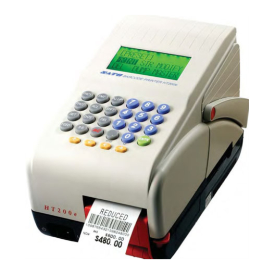
SATO HT200e Operator's Manual
Direct thermal printer
Hide thumbs
Also See for HT200e:
- Operator's manual (152 pages) ,
- Configuration manual (79 pages) ,
- Quick manual (37 pages)
Table of Contents
Advertisement
Quick Links
Advertisement
Table of Contents
Troubleshooting

Related Manuals for SATO HT200e


Summary of Contents for SATO HT200e
- Page 1 HT200e Direct Thermal Printer OPERATOR MANUAL PN 9001103B...
- Page 2 All rights reserved. No part of this document may be reproduced or issued to third parties in any form whatsoever without the express permission of SATO America, Inc. The materials in this document is provided for general information and is subject to change without notice. SATO America, Inc. assumes no responsibilities for any errors that may appear.
-
Page 3: Table Of Contents
Interface Modules Character Font Capabilities Charcater Control Symbologies Other Features Accessories Regulatory Approvals INSTALLATION Unpacking & Parts Identification Printer Installation Site Location Media Selection Media Loading Interface Selection RS232 Serial Interface Specifications RS232 Interface Signals RS232 Cable Requirements Accessories Installation... - Page 4 OPERATION Printer Configuration Entering Alphanumerics & Symbols Initial Setup Mode User Mode Data Maintenance Mode Copy Print Parameters Mode Send/Receive Preset Data Mode Copy Preset Data Mode Copy Font Mode Copy Table Data Mode Copy All Parameters Mode Country Code Mode...
- Page 5 TROUBLESHOOTING LCD Error Signals Troubleshooting Table RS232 Serial Interface Troubleshooting Hex Dump Printing ASCII Dump Mode Check Online Connection Check Scanner Operation Test Module Usage Test Module Dial MAINTENANCE Cleaning Procedures Replacement Procedures Print Head Power Switch Memory Backup Battery Adjustment Procedures Print Head Alignment Print Head Balance...
- Page 6 PN 9001103B...
-
Page 7: Introduction
INTRODUCTION SATO HT200e Operator Manual • About This Manual • General Description • Primary Components • Control Features PN 9001103B Page 1-1... - Page 8 ABOUT THIS MANUAL This manual is laid out consistent with the product discussed and provides all of the information required for general printer installation, configuration, troubleshooting, and maintenance. For specialized programming, refer to the Programming Manual provided with the product.
- Page 9 Unit 1: Introduction GENERAL DESCRIPTION The HT200e is a small, compact printer designed specifically for point-of-usage labeling applications. It can be used as a stand alone printer with predefined formats or connected to a PC using an RS232C communications for variable labeling applications.
- Page 10 Allows a barcode scanner to be connected and used in conjunction with Scanner Port the printer. Permits a SATO Test Module and/or multimeter to be connected to Test Terminal troubleshoot electrical circuitry and to measure electrical values when adjusting potentiometers.
-
Page 11: Keypad Buttons
Delete Deletes data entered one character at a time. All Clear Clears all input data on the screen. ENTR Enter Confirms current action and proceeds to the next step. SATO HT200e Operator Manual FUNCTION PN 9001103B Page 1-5... - Page 12 Unit 1: Introduction SATO HT200e Operator Manual PN 9001103B Page 1-6...
-
Page 13: Technical Data
TECHNICAL DATA SATO HT200e Operator Manual • Physical Characteristics • Power • Processing • Enviromental • Print • Media • Sensing • Interface Modules • Processing • Character Font Capabilities • Character Control • Symbologies • Other Features • Accessories •... - Page 14 Type Speed Resolution Print Module (Dot Size) Maximum Print Width Maximum Print Length SATO HT200e Operator Manual 5.2 Inches (132 mm) 5.94 Inches (151 mm) 9.06 Inches (230 mm) 5.5 Pounds (2.5 Kg) Autoswitching 100-120/200-240 VAC, 50-60 Hz NiMH, 8.4VDC 2.4 AH...
-
Page 15: Media
Outline 2 Outline 3 CHARACTER CONTROL Expansion Rotation Pitch SATO HT200e Operator Manual Die-Cut & Fan-Fold Labels, Tags (Face Up Stack), Continuous 1.1 Inches (28 mm) 0.63 Inches (16 mm) 2.0 Inches (51 mm) 4.0 Inches (103 mm) 0.007 Inches (0.18 mm) 2.95 Inches (75 mm) Wound Face-In... -
Page 16: Symbologies
Wand Scanner CCD Scanner REGULATORY APPROVALS Safety RFI/EMI SATO HT200e Operator Manual UPC-A/E, EAN-8/13, Code 39, I 2/5, Codabar, Code 128B/C Sequential numbering of both numerics and bar codes. Up to 24 Currency Marks BW Graphic files in BMP format... -
Page 17: Installation
INSTALLATION SATO HT200e Operator Manual • Unpacking • Parts Identification • Printer Installation • Interface Selection • Accessories Installation PN 9001103B Page 3-1... -
Page 18: Unpacking & Parts Identification
2 Open the box, remove any loose items and the first layer of packing material. 3 Carefully lift the printer and accessories from the box and place them on a solid flat surface. 4 Remove the plastic covers from the packed items and visually inspect for physical damage. -
Page 19: Printer Installation
The size and type of the labels or tags to be printed should have been taken into consideration before printer purchase. Ideally, the media width will be equal to, or just narrower than, the print head. Using media that does not cover the print head, will allow the platen roller to tread on it and wear it out. - Page 20 Unit 3: Installation Figure 3-3a Figure 3-3d Figure 3-3g Figure 3-3j SATO HT200e Operator Manual Figure 3-3b Figure 3-3e Figure 3-3h Figure 3-3k PN 9001103B Figure 3-3c Figure 3-3f Figure 3-3i Figure 3-3l Page 3-4...
-
Page 21: Interface Selection
Unit 3: Installation INTERFACE SELECTION The HT200e has two integrated interface connectors accessible on the printer’s left front side. One is a RS232C serial used for interfacing with a host computer and the other is for use with an optional scanner to input variable data by reading barcode symbols from a menu sheet. -
Page 22: Accessories Installation
Unit 3: Installation ACCESSORIES INSTALLATION There are several optional accessories that are available to make the HT200e printer more useful in certain applications. • Battery Power Module • PCMCIA Memory Card • Scanner BATTERY POWER MODULE The optional Battery Power Module attaches to bottom of the printer the same as the included AC Power Module. -
Page 23: Pcmcia Memory Card
The scanner option can be used to input variable data by reading barcode symbols from a menu sheet. Open the interface cover (Figure 3-6a). Connect the scanner to the scanner connector (Figure 3-6b). Figure 3-6a SATO HT200e Operator Manual Figure 3-5b Figure 3-6b PN 9001103B Figure 3-5c... - Page 24 Unit 3: Installation SATO HT200e Operator Manual PN 9001103B Page 3-8...
-
Page 25: Printer Configuration
OPERATION SATO HT200e Operator Manual • Printer Configuration • Configuration Modes • Fixed Formats • Customizing Label Formats • Operational Modes • Operational Adjustments PN 9001103B Page 4-1... -
Page 26: Entering Alphanumerics & Symbols
Unit 4: Operation PRINTER CONFIGURATION The printer may be configured for specific jobs via the operator panel located on the top surface of the printer. The operator panel is comprised of a keypad and a LCD panel. Once the printer has been configured, the settings are retained in the battery backup memory. -
Page 27: Initial Setup Mode
Unit 4: Operation INITIAL SETUP MODE Is the first menu in the printer configuration process. Typically, these values will not change following initial printer setup. CHECK LABEL PRINT PRESET NO. PRINT NO PRINT SATO HT200e Operator Manual POWER ON FORMAT NO. -
Page 28: User Mode
4800 BPS 9600 BPS 800 BPS CODE PAGE SET EURO CALC CM=E E=CM REPRINT FUNC CALENDAR DISP SATO HT200e Operator Manual DATA BIT SETTING 7 BITS 8 BITS Use arrow keys to cursor. Press ENTR to advance. PARITY SETTING EVEN... -
Page 29: Data Maintenance Mode
Press CARD CLEAR Press Press ENTR Refer to Memory Card Clear Mode Refer to Select Currency Mode SATO HT200e Operator Manual 6 + POWER PARAMETER COPY PRINTER CARD Press Press ENTR EAN COUNTRY CODE Refer to Copy Print Press Parameters To go back. -
Page 30: Copy Print Parameters Mode
COPY PRINT PARAMETERS MODE This menu provides the flow sequence of copying print parameters from the host and sending them to the printer or copying from the printer and sending them to the host. This menu is accessed through the Data Maintenance Mode. -
Page 31: Send/Receive Preset Data Mode
Unit 4: Operation SEND/RECEIVE PRESET DATA MODE This menu provides the flow sequence of sending or receiving preset data from the host or printer. This menu is accessed through the Data Maintenance Mode. Press ENTR STR / RCL DATA INT RAM... -
Page 32: Copy Preset Data Mode
Unit 4: Operation COPY PRESET DATA MODE This menu provides the flow sequence of copying preset data from the host to the printer or vice versa. This menu is accessed through the Data Maintenance Mode. Press ENTR STR / RCL DATA... -
Page 33: Copy Font Mode
Unit 4: Operation COPY FONT MODE This menu provides the flow sequence of copying font types from the host to the printer and vice versa. This menu is accessed through the Data Maintenance Mode. Press ENTR HOST SEND OK? Press... -
Page 34: Copy Table Data Mode
Unit 4: Operation COPY TABLE DATA MODE This menu provides the flow sequence of copying table data from the host to the printer or vice versa. This menu is accessed through the Data Maintenance Mode. Press ENTR HOST SEND OK? -
Page 35: Copy All Parameters Mode
Unit 4: Operation COPY ALL PARAMETERS MODE This menu provides the flow sequence of copying print parameters from the host to the printer or vice versa. This menu is accessed through the Data Maintenance Mode. SATO HT200e Operator Manual Refer to... -
Page 36: Country Code Mode
Country; specific symbols, features, and calculations are automatically initiated as part of the operational function. Each Country is assigned a two-digit code for this selection process. This menu is accessed through the Data Maintenance Mode. SATO HT200e Operator Manual Refer to Data Maintenance... -
Page 37: Memory Card Clear Mode
Unit 4: Operation MEMORY CARD CLEAR MODE Allows the selected values stored on the memory card to be cleared from its memory. This menu is accessed through the Data Maintnenance Mode. SATO HT200e Operator Manual Refer to Data Maintenance Mode... -
Page 38: Select Currency Mode
Unit 4: Operation SELECT CURRENCY MODE Allows the desired currency to be selected independently of the Country previously selected. Typically, the currency selected will be representative of the Country selected. Press ENTR SATO HT200e Operator Manual Refer to Data Maintenance Mode... -
Page 39: Fixed Formats
Unit 4: Operation FIXED FORMATS This unit identifies and defines the 29 pre-programmed label designs that are part of the HT200e printer package. These fixed formats are suitable for a wide variety of general uses. NOTE: The folowing text references PLU. PLU (Price Lookup) is the... - Page 40 Also has human readable code. Format 14 Two EAN 8 barcodes. Not normally PLU. Includes price and three-digit human readable code. SATO HT200e Operator Manual Format 11 EAN 13 Barcode. Needs a Non PLU flag. Has five-digit item code and five-digit price.
-
Page 41: Price Reductions
Enter the non-discounted (WAS) price. The printer calculates the discounted (NOW) price. Format 19 Enter the non-discounted (WAS) price. The printer calculates the discounted (NOW) price. SATO HT200e Operator Manual Format 17 Enter the EAN 13 Barcode and non-discounted (WAS) price. -
Page 42: Simple Data And Price
SHELF EDGE LABEL Format 22 Contains one line of 20 alphanumeric characters, plus tow of ten digits, a price, and the EAN 13 barcode. SATO HT200e Operator Manual Format 13 Contains two lines of 15 alphanumeric charcters and the price. Format 24 Enter the pre-tax amount and the EAN 13 barcode data. -
Page 43: Unit Pricing
Enter the local currency. The printer calculates the Euro value. Data is needed for the EAN 13 barcode. SATO HT200e Operator Manual Format 27 When promted to enter “Unit Voles”, press [FNC1] to select the number of units. Press Enter. -
Page 44: Customizing Label Formats
Figure 7-1 displays a sample label. Since all programming is numerical, the format name, the label name, and all configuration entries will be made by using the printer’s keypad. The following procedure generalizes the programming sequence when prompted by the LCD: Enter a format number for the label. -
Page 45: Programming Process
Print Configuration Print? Table & Chart Yes / No 7-13 NOTE: A calendar field cannot be copied. For Normal/Table data, a copy cannot be received. SATO HT200e Operator Manual 03: FONT TYPE 0: X1 1: X2 2: X3 Configuration Options 1000000000000000000 Configuration Entry will Display here. -
Page 46: Beginning A Customized Label
[ ..] SHFT to scroll options, Press ENTR Refer to relative table & chart to continue. Figure 4-9a, Beginning a Customized Label SATO HT200e Operator Manual POWER ON FORMAT NO. [ . . ] HT200e PARAMETER Press ENTR FORMAT No [ . -
Page 47: Normal Field Configuration
Press SHFT to scroll options. XXXXXXXXXX000000000 11: CHAR PITCH XXXXXXXXXXX00000000 12: CHAR COUNT XXXXXXXXXXX00000000 14: V - EXPANSE XXXXXXXXXXXXXX00 SATO HT200e Operator Manual 15: H - EXPANSE XXXXXXXXXXXXXXX0 LCD. 16: INPUTCHECK 0: NO CHECK XXXXXXXXXXXXXXXX 17: SET TITLE X00000000000000000000 18: 0 RESERVED... - Page 48 Title Setup Reserved Insertion whether a leading or trailing zeroes are inserted) Preset Font Color SATO HT200e Operator Manual 10: Normal 0: X1 1: X2 2: X3 4: OCR-B 001 to 784 dots: Vertical print position. 000: Entry only, where print is not required.
-
Page 49: Table Field Configuration
Unit 4: Operation TABLE FIELD CONFIGURATION Fields of tabulated data may be stored in the printer’s memory and linked to another field type to be displayed when scanned. XX: FLD TYPE X: *********** 000000000000000000000 Enter numeral/s at each screen to configure. - Page 50 Horizontal Expansion Input Check Title setup Table number setup 0 Insertion Preset Font Color SATO HT200e Operator Manual 11: Table 0: X1 1: X2 2: X3 4: OCR-B 001 to 784 dots: Vertical print position. 000: Entry only, where print is not required.
-
Page 51: Sequential Number Field Configuration
XXXXXXXXXX000000000 11: CHAR PITCH XXXXXXXXXXX00000000 12: CHAR COUNT XXXXXXXXXXX00000000 14: V - EXPANSE XXXXXXXXXXXXXX00 Figure 4-9d, Sequential Number Field Configuration SATO HT200e Operator Manual 15: H - EXPANSE XXXXXXXXXXXXXXX0 16: INPUTCHECK 6: FULL NUMERIC XXXXXXXXXXXXXXXX 17: SEQ 0: SEQUENCE NONE... - Page 52 Reserved Insertion whether a leading or trailing zeroes are inserted) Preset Font Color Table 4-9d, Sequential Number Field Configuration SATO HT200e Operator Manual DESCRIPTION 12: Normal 0: X1 1: X2 2: X3 4: OCR-B 001 to 784 dots: Vertical print position.
-
Page 53: Price Field Configuration
Press SHFT to scroll options. XXXXXXXXXX000000000 11: CHAR PITCH XXXXXXXXXXX00000000 12: CHAR COUNT XXXXXXXXXXX00000000 14: V - EXPANSE XXXXXXXXXXXXXX00 SATO HT200e Operator Manual configure. Numeral 15: H - EXPANSE LCD. XXXXXXXXXXXXXXX0 16: INPUTCHECK 5: NUM ONLY XXXXXXXXXXXXXXXX 17: INP METHOD... - Page 54 Character Count Vertical Expansion Horizontal Expansion Input Check Input Method Insertion 0 Insertion Preset currency mark. Reserved SATO HT200e Operator Manual 20: Normal Normal: 0: X1 1: X2 2: X3 5: Price character POP: 0: POP1 1: POP2 2: POP3 001 to 784 dots: Vertical print position.
-
Page 55: Calendar Field Configuration
XXXXXXXXXX000000000 11: CHAR PITCH XXXXXXXXXXX00000000 12: CHAR COUNT XXXXXXXXXXX00000000 14: V - EXPANSE XXXXXXXXXXXXXX00 Figure 4-9f, Calendar Field Configuration SATO HT200e Operator Manual XX: FIELD TYPE configure. Numeral is displayed on bottom 15: H - EXPANSE row of LCD. XXXXXXXXXXXXXXX0... - Page 56 Input Check Addition Presentation Format Symbol calendarr data Preset Reserved SATO HT200e Operator Manual 30: Date 31: Time 1: X2 2: X3 001 to 784 dots: Vertical print position. 000: Entry only, where print is not required. 001 to 384 dots: Horizontal print position.
-
Page 57: Barcode Field Configuration
12: CHAR COUNT XXXXXXXXXXX00000000 14: BAR RATIO Press SHFT to 0: FIXED scroll options. XXXXXXXXXXXXXX00 Figure 4-9g, Barcode Field Configuration SATO HT200e Operator Manual XX: FIELD TYPE each screen to configure. Numeral will display on 15: BAR EXPANS bottom row of XXXXXXXXXXXXXXX0 LCD. - Page 58 Bar Expansion 16, 17, 18 Bar Height Check digit (when Code 128 is being set, specify “1”). Preset Reserved SATO HT200e Operator Manual 70: Readable> 71: Not readable. 0: NW-7 1: CODE39 2: INT2of5 3: EAN13 4: EAN8 5: UPC-E...
-
Page 59: Copy Configuration
35, 36 37, 38 39, 40 Copy 3 41, 42 43, 44 45, 46 SATO HT200e Operator Manual 31: COPY 2 - 1 XXXXXXXXXXXXXX0000 33: COPY 2 - 2 X0000000000000000000 35: COPY 2 - 3 XXX0000000000000000 37: COPY 2 - 4... -
Page 60: Print Quantity Configuration
DIGIT POSITIONS DESIGNATED ITEM 1, 2 Print Quantity Quantity 4 to 15 Reserved Count Figure 4-9i, Print Quantity Configuration SATO HT200e Operator Manual XX: FIELD TYPE X: *********** 000000000000000000000 Enter numeral to designate field number & field type. Numeral is displayed on bottom row of LCD. -
Page 61: Discount Rate Configuration
Unit 4: Operation DISCOUNT RATE CONFIGURATION Where applicable, this menu allows the discount rate to be configured. Figure 4-10, Discount Rate Configuration SATO HT200e Operator Manual POWER FORMAT NO. [ . . ] HT200e Refer to relative Fixed Formats 16, 17, 18, 19, 25. -
Page 62: Tax Rate Configuration
Unit 4: Operation TAX RATE CONFIGURATION Where applicable, this menu allows the tax rate to be configured. SATO HT200e Operator Manual POWER FORMAT NO. [ . . ] HT200e Refer to relative Fixed Formats. Enter 23 or 24. Press ENTR. -
Page 63: Operational Modes
OPERATIONAL MODES This unit provides instruction on the various modes used in operation. ONLINE MODE This operational mode permits printing activity when the print data is received from the host. SATO HT200e Operator Manual POWER FORMAT NO. [ . . ]... -
Page 64: Table Data Mode
....MODIFY TABLE NO. [ . . . ] DELETE TABLE NO. [ . . . ] TABLE DATA DEL SATO HT200e Operator Manual POWER ON FORMAT NO. [ . . ] HT200e FNC1... -
Page 65: Preset Data Mode
PRESET NO. INPUT ..<DELETE> DUMP FROM INT RAM OPT CARD PRESET NO. INPUT …… - ...… MASTER SATO HT200e Operator Manual RCL + POWER MODIFY DUMP MODIFIER Press to scroll options. Press ENTR Enter preset PRESET NO. INPUT number. -
Page 66: Preset Data Storage
This operational mode permits the storage of preset data. [ . . ] [ PRESET ] PRINT PRESET F-NO. [ . . ] PRESET NO. INPUT ..SATO HT200e Operator Manual POWER FORMAT NO. HT200e Press MODIFY DUMP MASTER Enter data as required. -
Page 67: Suspending A Print Job
Unit 4: Operation SUSPENDING A PRINT JOB This operational mode provides instruction on how to suspend a print job once initiated. SATO HT200e Operator Manual PRINTING Continue? Press Yes / No S/S PRINT REMAIN QTY: 0001 Printing ceases. Press Begin again? -
Page 68: Reprinting A Label
Reprints the last label with the sequential variable incremented or decremented accordingly. SATO HT200e Operator Manual Format has printed. [ITEMSQ] ... . . C Determine Reprint? what next. Refer... -
Page 69: Data Entry Edit
The black blinking cursor indicates where the next typed character will appear. Use the arrow keys on the printer keypad to move the cursor in the direction desired for entry or edit. If an additional character was accidentally typed, move the cursor to the right of the accidental character and press DEL once. -
Page 70: Operational Adjustments
If all else fails, the main circuit board will have to be replaced. This adjustment procedure will require the use of a multimeter and the SATO Test Module. The voltage level may also be checked by connecting the multimeter probes directly to the CH1a (-) and the CH1b (+) pins of the test terminal and following steps 6 through 12 of the procedure below. -
Page 71: Dispenser Sensor Adjustment
Procedures unit of this manual. If all else fails, the main circuit board will have to be replaced. This adjustment procedure will require the use of a multimeter and the SATO Test Module. The voltage level may also be checked by connecting the multimeter probes directly to the CH1a (-) and the CH2b (+) pins of the test terminal and following steps 6 through 12 of the procedure below. -
Page 72: Pitch Adjustment
Ensure the multimeter is set for DC reading. Turn the VR2 potentiometer to the 12 o’clock position. Press and hold the [9] key while switching on the printer to enter the Service Mode. At the TEST PRINT screen, press ENTR to proceed to the test print options. -
Page 73: Dispense Stop Position
The brightness of the LCD panel may be adjusted through a potentiometer integrated into the bottom side of the main circuit board. To access the VR5 potentiometer, remove the battery cover located on the bottom of the printer chassis. Adjust the potentiometer to the desired result and replace the cover. - Page 74 Unit 4: Operation SATO HT200e Operator Manual PN 9001103B Page 4-50...
-
Page 75: Troubleshooting
TROUBLESHOOTING SATO HT200e Operator Manual • LCD Error Signals • Troubleshooting Table • Troubleshooting Procedures • Test Module Usage PN 9001103B Page 5-1... - Page 76 PRESET FULL Preset data at max capacity. NO DUMP ERR Cannot dump presets. BLANK PRESET NO Preset number is not registered. Check preset number and re-enter. SATO HT200e Operator Manual CAUSE CORRECTIVE ACTION No paper. Improperly loaded paper. Sensor adjustment.
- Page 77 Damaged electronics. WILL NOT GO ON-LINE Defective power supply cord. House power supply discontinued. Battery pack power depleted. SATO HT200e Operator Manual Use high quality label stock. Replace print head. Replace platen. Use high quality direct thermal label stock. Adjust darkness level.
-
Page 78: Rs232 Serial Interface Troubleshooting
Print a Configuration Test Label to determine the RS232 settings. • Ensure the printer is recieving from the computer using the Hex Dump Mode. Refer to that procedure for instructions. The printer will print (only once) a hexadecimal dump of everything it has received from the host computer. -
Page 79: Hex Dump Printing
And in the right column, the same data is provided in the ASC II format. Follow the flow chart provided below to perform this activity. POWER FORMAT NO. [ . . ] HT200e [HEX DUMP MODE] Prints Label Power = Off Figure 5-1, Hex Dump Mode SATO HT200e Operator Manual PN 9001103A Page 5-5... -
Page 80: Ascii Dump Mode
The ASCII Dump Mode prints all recieved data in ASCII format. The flow chart below provides guidance. POWER FORMAT NO. [ . . ] HT200e [ASC DUMP MODE] Prints Label Power = Off Figure 5-2, ASCII Dump Mode SATO HT200e Operator Manual PN 9001103B Page 5-6... -
Page 81: Check Online Connection
Unit 5: Troubleshooting CHECK ONLINE CONNECTION SATO HT200e Operator Manual With the printer off, connect host and printer with RS232C interface. Then turn printer on. FORMAT No. [ 00 ] HT200e Enter 70. FORMAT No. [ 70 ] HT200e Send test print from host. -
Page 82: Check Scanner Operation
Unit 5: Troubleshooting CHECK SCANNER OPERATION SATO HT200e Operator Manual Connect scanner to printer. Turn printer on. FORMAT No. [ 00 ] HT200e Enter 20. FORMAT No. [ 20 ] HT200e Press ENTR. Scanning begins. The following screen confirms scanner is operational. -
Page 83: Test Module Usage
Unit 5: Troubleshooting TEST MODULE USAGE The SATO TP Test Module is a purchase option specially designed and sold by SATO America to assist in troubleshooting SATO Printers. The use of this device will facilitate the identification and isolation of problem circuitry and for voltage adjustment. -
Page 84: Test Module Dial
Unit 5: Troubleshooting TEST MODULE DIAL MODULE DIAL PIN ASSIGNMENT 3A / 1A 4A / 1A 5A / 1A 6A / 1A SATO HT200e Operator Manual SPECIFICATION +4.8V to +5.3V +3.1V to +3.5V +1.9V to 2.1V +8.2V to +8.7V PN 9001103B APPLICATION +5.0V Power Supply... -
Page 85: Maintenance
MAINTENANCE SATO HT200e Operator Manual • Cleaning Procedures • Replacement Procedures • Adjustment Procedures • Service Modes PN 9001103B Page 6-1... - Page 86 This process should be performed prior to the removal of residue. To remove residue, apply SATO Solvent or isopropyl alcohol to a clean cotton swab and gently wipe the entire surface of the print head, platen roller, and dispenser roller until clean.
- Page 87 Unit 6: Maintenance REPLACEMENT PROCEDURES The printer contains replaceable components and sub-assemblies that are subject to wear or damage. This section provides step-by-step instructions for the removal and replacement of those primary components and sub-assemblies approved for operator performance. PRINT HEAD REPLACEMENT If the print head becomes damaged or worn, it can be easily removed and replaced without having to make critical adjustments.
- Page 88 POWER SWITCH REPLACEMENT The power switch is located on the front of the printer to the left of the dispenser. The power switch is of a simple on/off variety that completes the circuit when in the “on” position and breaks the circuit when “off”.
-
Page 89: Print Head Alignment
It may be necessary to refer to this chapter following component replacement. Use the relative procedure in that chapter to replace the component, test cycle the printer, and then adjust as necessary in accordance to the relative procedures in this chapter. -
Page 90: Belt Tension
Unit 6: Maintenance BELT TENSION ADJUSTMENT The printer has two timing belts that may require adjustment. The belt configuration transfers the timing sequence from the drive motor to the platen roller. If the timing belts become loose enough, media feeding will become erratic affecting print location from label to label. A properly tensioned belt will be tight enough to prevent slippage, but loose enough to avoid undue lateral pressure on the motor spindle and the platen roller shaft. -
Page 91: Eye-Mark Sensor
If all else fails, the main circuit board will have to be replaced. This adjustment procedure will require the use of a multimeter and the SATO Test Module. The voltage level may also be checked by connecting the multimeter probes directly to the CH1a (-) and the CH1b (+) pins of the test terminal and following steps 6 through 12 of the procedure below. -
Page 92: Dispenser Sensor
Procedures unit of this manual. If all else fails, the main circuit board will have to be replaced. This adjustment procedure will require the use of a multimeter and the SATO Test Module. The voltage level may also be checked by connecting the multimeter probes directly to the CH1a (-) and the CH2b (+) pins of the test terminal and following steps 6 through 12 of the procedure below. -
Page 93: Pitch
Ensure the multimeter is set for DC reading. Turn the VR2 potentiometer to the 12 o’clock position. Press and hold the [9] key while switching on the printer to enter the Service Mode. At the TEST PRINT screen, press ENTR to proceed to the test print options. -
Page 94: Lcd Brightness
The brightness of the LCD panel may be adjusted through a potentiometer integrated into the bottom side of the main circuit board. To access the VR5 potentiometer, remove the battery cover located on the bottom of the printer chassis. Adjust the potentiometer to the desired result and replace the cover. -
Page 95: Service Mode
ENTR TEST PRINTING single label prints. Print Again? Yes / No Press PG UP Press To go back. Press SATO HT200e Operator Manual 9 + POWER TEST PRINT Press Press ENTR To go back. Displays battery voltage. Ram backup battery capacity. -
Page 96: Hex Dump Mode
ASCII format. POWER FORMAT NO. [ . . ] HT200e [HEX DUMP MODE] Prints Label Power = Off Figure 6-6, Hex Dump Mode SATO HT200e Operator Manual PN 9001103B Page 6-12... -
Page 97: Ascii Dump Mode
ASCII DUMP MODE Allows printing of data in the ASCII format. POWER FORMAT NO. [ . . ] HT200e [ASC DUMP MODE] Prints Label Power = Off Figure 6-7, ASCII Dump Mode SATO HT200e Operator Manual PN 9001103A Page 6-13... -
Page 98: Print Head & Life Counter Clear
Permits the print head and/or life counter to be cleared. This is typically performed following component replacement or major service. Successful FORMAT NO. [ . . ] Figure 6-8, Print Head & Life Counter Clear SATO HT200e Operator Manual 1 + DEL + POWER COUNTER CLEAR? LIFE HEAD Press to scroll options. -
Page 99: Test Print Mode
Unit 6: Maintenance TEST PRINT MODE This mode allows the operator or service technician to print test labels for troubleshooting and for verification of configuration settings. SATO HT200e Operator Manual 9 + POWER TEST PRINT Press ENTR LABEL TYPE NORMAL... -
Page 100: Sram Clear Mode
Unit 6: Maintenance SRAM CLEAR MODE Permits SRAM contents to be cleared. SATO HT200e Operator Manual 6 + POWER MEMORY CLEAR? YES / NO Press to scroll options. Press Clear? ENTR Yes / No PASSWORD [ . . . ]...