Table of Contents
Advertisement
Quick Links
Potential for Fire, Smoke and Asphyxiation Hazards
Incorrect installation, adjustment, or misuse of this burner could result in death, severe
personal injury, or substantial property damage.
To the Homeowner or Equipment Owner:
Please read and carefully follow all instructions
provided in this manual regarding your
responsibilities in caring for your heating
equipment.
Contact a professional, qualifi ed service agency for
installation, start-up or service work.
Save this manual for future reference.
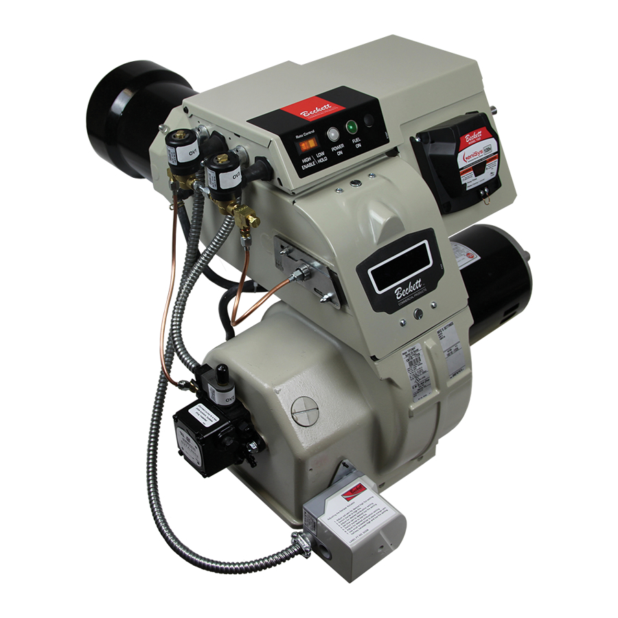
COMMERCIAL PRODUCTS
To the Professional, Qualifi ed Installer or Service Agency:
Please read and carefully follow all instructions provided
in this manual before installing, starting, or servicing this
burner or heating system.
The Installation must be made in accordance with all state
and local codes having jurisdiction.
Advertisement
Table of Contents

Related Manuals for Beckett CF2500


Summary of Contents for Beckett CF2500
- Page 1 Potential for Fire, Smoke and Asphyxiation Hazards Incorrect installation, adjustment, or misuse of this burner could result in death, severe personal injury, or substantial property damage. To the Homeowner or Equipment Owner: Please read and carefully follow all instructions provided in this manual regarding your responsibilities in caring for your heating equipment.
-
Page 2: Table Of Contents
Your Beckett burner will provide years of effi cient oper- ation if it is professionally installed and maintained by a qualifi ed service technician. If at any time the burner does not appear to be operating properly, immediately contact your qualifi... -
Page 3: General Information
Canada #1 stove oil or #2 furnace oil only CRANKCASE OIL, OR ANY OIL CONTAINING GASOLINE. Firing Range CF2500A - 17.0 to 19.9 gph CF2500 - 17.0 to 25.0 gph CF3500A - 17.0 to 35.0 gph Motor 2 HP 3450 rpm 208/230/60 Hz Standard 13.4 amps @ 230 VAC... -
Page 4: Combustion Air Supply
Clearances With the burner installed in the appliance, there must be adequate space in front of and on the sides of the burner to allow access and operation. Verify that the clearance dimensions comply with all local codes and with the appliance manufacturer’s recommendations. -
Page 5: Nozzle Pressure
8.70 9.54 rating label. 9.49 10.40 The CF2500A, CF2500, and CF3500A are dual nozzle 10.30 11.25 burners. To select the nozzles, use half of the maximum 11.06 12.12 fi ring rate and select a nozzle under the 300 psig column. -
Page 6: Verify Air Tube
* Install burner with 2° pitch as shown. The following tube arrangements are available – ○ CF2500 - Tube KP -17.0.0 to 19.9 GPH ○ CF2500A - Tube KP -17.0 to 25.0 GPH ○ CF3500A - Tube KM -17.0 to 35.0 GPH or Maximum fi... -
Page 7: Dust And Moisture
○ The control must detect a dark, no-fl ame condition in order to start the burner or it will hold in the stray light lockout mode. ○ Shield the burner view window from direct exposure to intense light. -
Page 8: Mount Air Tube To Burner
Remove the rear access door from the back of the burner for improved access to the interior. ○ Attach the air tube to the burner with the bolts and acorn nuts provided. The acorn nuts must go on the outside of the burner, with the bolts inserted from the inside. -
Page 9: Set Dimension Z
See Figure 8. Install the pedestal support kit (recommended) by attaching the 3/4” NPT fl ange (item a) to the bottom of the burner using the (4) #10 screws provided. Cut and thread (one end only) a 3/4” pipe nipple (item b) with length 11 inches less than dimension D in Figure 8. -
Page 10: Connect Fuel Lines
fi re and injury hazards. Models CF2500A/CF2500/CF3500 are shipped with the pump by-pass plug installed. Do not remove the by-pass plug from the pump. It is required for step-fi... - Page 11 Figure 10 – Two-pipe Oil Flow 200 psig 300 psig 200 psig 300 psig CF2500/CF3500 Burner Manual Section: Connect Fuel Lines Nozzle Pressure – The fuel unit nozzle port pressure is factory set at 300 psig. Some original equipment manufacturer burner applications may call for a lower pressure to obtain a required fi...
-
Page 12: Wire The Burner
If terminals RC1 and RC2 are jumpered, the burner operates in the Low-High-Off Mode. The burner starts at Low, goes to High after the fl ame stabilization period. Flame is extinguished when the load is satisfi ed or a limit opens, and the burner is sent to Motor-Off Delay. -
Page 13: Cad Cell Resistance Measurement
Thermostat Terminals CF2500/CF3500 Burner Manual Cad Cell Resistance Measurement: Pump If the Beckett 7505 control is equipped with the Prime GeniSys Display Module, part 52067U, the cad cell resistance can be selected and read on the LCD screen. Also, the GeniSys Contractor Tool, part 52082U, can be used for this purpose. - Page 14 Section: Wire the Burner Figure 13 –Typical Wiring (7505P)
-
Page 15: Typical Burner Sequence Of Operation - Rm7897A Control
Typical Burner Sequence of Operation - RM7897A Control When fi ring over 20 GPH the CF2500 and CF3500A will be supplied with a fl ame safeguard control. An airfl ow switch and low-fi re start relay will also be supplied. - Page 16 If any of these items are not clear or are unavailable, call Beckett at 1-800-645-2876 for assistance. Do Not Bypass Safety Controls Tampering with, or bypassing safety controls could lead to equipment malfunction and result in asphyxiation, explosion or fi...
-
Page 17: Z Dimension
○ Slide the secondary adjusting plate (item f) toward the rear of the burner until the number on the indicator plate corresponds to the initial head setting given in Table 6 for the desired fi ring rate and burner (high-fi re). -
Page 18: Initial Air Settings
If your burner was built for a specifi c OEM application, the “Mfr’s Settings” label (see Figure 1) will indicate the application and the initial air settings made at Beckett. Please verify those settings using the following procedure. If your burner was not built for a specifi ed application,... -
Page 19: Set Appliance Limit Controls
○ Move the low-fi re hold switch (not shown) to the low fi re hold position. This will hold the burner in low fi re during initial start-up. Prepare the Fuel Unit for Air Venting To vent air from one-pipe oil systems, attach a clear hose to the pump bleed port (item p in Figures 9 &... -
Page 20: Set High-Fi Re Air
If the CO 5.9%), decrease the air and check the smoke level. Operate the burner from low fi re to high fi re and back to verify operation. Turn the burner off. Wait one or two minutes (for chamber to clear) and then turn on again to verify starting characteristics. -
Page 21: Perform Regular Maintenance
fi re. Do not tamper with the burner or controls or make any adjustments unless you are a trained and qualifi ed service technician. To ensure continued reliable operation, a qualifi ed service technician must service this burner annually. -
Page 22: Replacement Parts
H Pump 8.25” X 4.18” 120/208-230 Single Phase 208-230/460 Three Phase 575 Three Phase 120V Single Phase 208V Single Phase Three Phase Refer to Figure 19 CF2500 Part No. CF3500 Part No. 21789U 21789U 3666 3666 5201703U 5201703U 21529U 21529U... - Page 23 Figure 18 - Burner Replacement Parts CF2500/CF3500 Burner Manual Figure 19 – Adjustable Mounting Plates Flange A Flange B Air Tube Flange A Model 51498 51498 Flange B 51630 51630 51631...
-
Page 24: Limited Warranty Information
The R. W. BECKETT CORPORATION (“Beckett”) warrants to persons who purchase its “Products” from Beckett for resale, or for incorporation into a product for resale (“Customers”), that its equipment is free from defects in material and workmanship. To qualify for warranty benefi ts, products must be installed by a qualifi...