
Related Manuals for MSI MEGA ePower 200AV+


Summary of Contents for MSI MEGA ePower 200AV+
- Page 1 MEGA ePower 200AV+ Powerline Network USER MANUAL (MEGA ePower 200AV+) Instant Networks for Internet Access…and More! Solution for SOHO, S MALL FFICE AND FFICE...
-
Page 2: Table Of Contents
GETTING TO KNOW THE ADAPTER ..................4 .....................4 THERNET NTERFACE ......................4 DAPTER UTTONS ......................4 DAPTER HOW TO INSTALL UTILITY .......................5 HOW TO USE MSI UTILITY SOFTWARE................7 ..........................7 .........................10 RIVACY .........................12 IAGNOSTICS ...........................14 BOUT HOW TO USE THE NMK PUSHBUTTON ................15 ..............15... -
Page 3: Introduction
MEGA ePower 200AV+ USER MANUAL 1 Introduction This MEGA ePower 200AV+ (wallmount PLC passthrough product) transmitting data will up to 200 Mbit/s across the household power line. And every power socket becomes a connection, and no new wire. You do not even have to do without an outlet, as this product provides a female socket to which you can connect your terminal devices or power stripe. -
Page 4: System Requirements
Figure 1-1 PLC Application 1.3 System Requirements Operating System Microsoft Windows 2000 or XP , Vista 32-bit Intel Pentium III or better, clock rate faster than 2.0GHz recommended At least 128MB Screen Resolution Any resolution Free Disk Space At least 20MB Network Interface At least one Fast Ethernet (100 Mbps) network card, and Ethernet Cord... -
Page 5: Safety Notice
2 Safety Notice: This device is intended for connection to the AC power line. For installation instructions, please refer to the installation section of this guide. The following precautions should be taken when using this product. Read all instructions before installing and operating this product. Follow all warnings and instructions marked on the product. -
Page 6: Getting To Know The Adapter
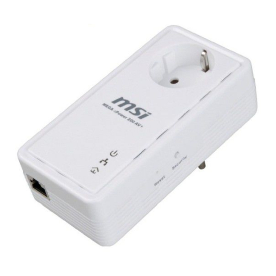
3 Getting to Know the Adapter 3.1 The Ethernet Interface Ethernet : The Ethernet port connects to an Ethernet network cable. The other end of the cable will connect to your computer or other Ethernet-enabled network device. 3.2 The Adapter's Buttons RST: The button can restore the factory defaults and reset the device. -
Page 7: How To Install Utility
Second step, please insert the Utility CD-ROM into the computer’s CD-ROM drive. Find the Utility Setup file as below: X:\ ePower 200AV+\SOFTWARE\MSI ePower 200AV+ Utility_EN\Power Packet5.0. Click the setup.exe and the Next button to continue. - Page 8 Figure 4-2 Select Installation Folder Figure 4-3 Installation Complete Click “Close” to complete installation.
-
Page 9: How To Use Msi Utility Software
5 How to Use MSI Utility Software 5.1 Main Tab The Main screen provides a list of all Powerline devices logically connected to the computer when the utility is running. The top panel shows local HomePlug devices connected to the computer’s NIC (Network Interface Card). - Page 10 Device Name This column shows the default device name, which may be user re-defined. A user can change the name by either using the rename button or by clicking on the name and editing in-place. MAC Address This column shows the Remote device’s MAC address. Password This column by default is blank and “Enter Password”...
- Page 11 Figure 5-3: Add Remote Device Note: The device must be present on the power line (plugged in) in order for the password to be confirmed and added to the network. If the device could not be located, a warning message will be shown. Scan This button is used to perform an immediate search of the HomePlug devices connected to the Powerline network.
-
Page 12: Privacy Tab
5.2 Privacy Tab The Privacy screen provides the user with an option to maintain security for their logical network and also to select the devices that has to be included in the network. The appearance is shown in Figure 5-4. All HomePlug devices are shipped using a default logical network (network name), which is normally “HomePlug”. - Page 13 Set All Devices This button is used to change the logical network of all devices that appear on the Main panel whose Device’s Password had been entered for the same logical network. A dialog window will appear to report the success of this operation. For devices whose device password’s were not entered, this operation will fail and will report a failure message.
-
Page 14: Diagnostics Tab
5.3 Diagnostics Tab The Diagnostics screen shows System information and a history of all remote devices seen over a period of time. The appearance is shown in Figure 5-5. The Upper panel shows technical data concerning software and hardware present on the host computer which were used to communicate over HomePlug on the Powerline network. - Page 15 following remote device information is available from the diagnostics screen: Device Alias Name Device MAC Address Device Password Device Last known rate Device Last Known Network name HomePlug chipset manufacturer name Date device last seen on the network MAC Firmware Version The diagnostics information displayed may be saved to a text file for later use, or can be printed for reference for a technical support call.
-
Page 16: About Tab
5.4 About Tab The About screen shows the software version and provides an html link to the MSI website. Clicking on the web address field will open a web browser and take the user directly to the web site. Figure 5-6: About Dialog Tab... -
Page 17: How To Use The Nmk Pushbutton
6 How to use the NMK Pushbutton This section describes how to add new devices to, or remove old devices from a HomePlug AV logical network(AVLN), both can be accomplished using a NMK pushbutton press. Operation progress and outcome can be monitored by observing the behavior of the Power LED. -
Page 18: Leaving A Network
succeeds or fails. It will illuminate steadily on success. If an error occurs, the Power LED on the ‘adder’ will flash unevenly until the pushbutton on the ‘adder’ is pressed again or the ‘joiner’ is reset by pressing the pushbutton for more than 10 seconds. A and B form an AVLN A and B form an AVLN C wants to join the AVLN... -
Page 19: How To Improve The Transmission Capacity
7 How to Improve the Transmission Capacity It is important to use the PLC product complying with the following "correct rules", because it can significantly improve the transmission capacity of the network. For the PLC device no female socket, it is recommended to plug the device directly into a wall socket, not to power stripe. -
Page 20: Appendix Aspecifications
Appendix A Specifications Chipset Intellon INT6400/INT1400 Protocol HomePlug AV 1.0 Co-exists with existing HomePlug 1.0 System Support Windows 98SE, 2000, ME, XP 32/64 bit and Vista 32/64bit PLC Rate 200Mb Modulation Band 2-30MHz Modulation Schemes Supports1024/256/64/16/8-QAM, QPSK,BPSK and ROBO Encryption 128 AES Outlet current 220VAC 16A Maximum,110VAC 20A Maximum... -
Page 21: Appendix Bacronyms And Abbreviations
Appendix B Acronyms and Abbreviations AVLN AV In-home Logical Network, the AVLAN is the set of STAs that possess the same network Membership key, every AVLN is managed by a single CCo Central Coordinator, the CCo is a superset of a STA which provisioning of terminal equipment identifiers and global link identifiers CSMA/CA... -
Page 22: Appendix Cabout Qos
Appendix C About QoS PLC 200AV allows for 4 levels of Channel Access Priority (CAP (0 – 3)). The 8 levels of VLAN Ethernet tags must be mapped to the 4 levels of CAP priority, where CAP 3 is the highest priority and CAP 0 is the lowest. CAP 3 priority might be used for voice and network management frames, CAP 2 is used for streaming video and music while CAP 1 and CAP 0 are used for data. -
Page 23: Contact Information
Appendix D Contact Information For help with the Installation or operation of the MSI Mega ePower 200AV+ adapter, please contact us. Technical Support : for all MSI Products w/o Notebooks Tel.: 01805-215 521 (0,12 €/Min. german landline!) Outside Germany pleas call: 0049-1805-215 521...