
Related Manuals for Carrier AquaForce 30XB series


Summary of Contents for Carrier AquaForce 30XB series
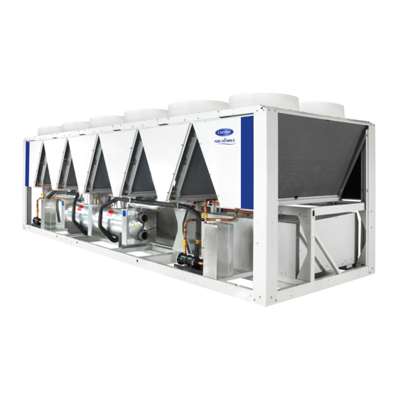
- Page 1 I N S TA L L AT I O N , O P E R AT I O N A N D M A I N T E N A N C E I N S T R U C T I O N S Unit with options 15 &...
-
Page 2: Table Of Contents
CONTENTS 1 - INTRODUCTION .................................... 4 1.1 - Installation safety considerations ..............................4 1.2 - Equipment and components under pressure ..........................5 1.3 - Maintenance safety considerations ............................. 5 1.4 - Repair safety considerations ............................... 6 2 - PRELIMINARY CHECKS ................................8 2.1 - Check equipment received ................................ - Page 3 CONTENTS 9 - HEAT RECLAIM CONDENSER OPTION (OPTION 50) ......................50 9.1 - Physical data,30XB & XBP units with heat reclaim condenser option ..................50 9.2 - Dimensions, clearances ................................50 9.3 - Condenser location ................................... 54 9.4 - Condenser water connections ..............................54 9.5 - Operating limits for stable operation (no mode changeover) ....................
-
Page 4: Introduction
Set up warnings and recommendations for personnel shipping company. in charge to stop the fire. Carrier strongly recommends employing a specialised Fire extinguishers appropriate to the system and the company to unload the machine. refrigerant type must be easily accessible... -
Page 5: Equipment And Components Under Pressure
In the EU, the regulation is called F-Gas, N°517/2014 Carrier recommends the following drafting for a logbook (the table below should not be considered as reference and does not involve 2. Ensure that the refrigerant is never released to the... -
Page 6: Repair Safety Considerations
If the recommendations above are not observed, this can have serious or even fatal consequences and damage the Consult Carrier Service for this type of test. Carrier mentions here installation. only the principle of a test without removing the pressure switch: Verify and record the set-points of pressure switches and Never exceed the specified maximum operating pressures. - Page 7 1 - INTRODUCTION Avoid spilling liquid refrigerant on skin or splashing it into Use only original replacement parts for any repair or the eyes. Use safety goggles and safety gloves. Wash any component replacement. Consult the list of replacement parts spills from the skin with soap and water.
-
Page 8: Preliminary Checks
2 - PRELIMINARY CHECKS 2.1 - Check equipment received 2.2 - Moving and siting the unit • Check that the unit has not been damaged during transport and that no parts are missing. If the unit has been damaged 2.2.1 - Moving or the shipment is incomplete, send a claim to the shipping See chapter 1.1 “Installation safety considerations”. - Page 9 2 - PRELIMINARY CHECKS 2.2.2 - Siting the unit 2.2.3 - Checks before system start-up The machine must be installed in a place that is not accessible to the Before the start-up of the refrigeration system, the complete installation, including the refrigeration system must be verified public or protected against access by non-authorised persons.
-
Page 10: Dimensions, Clearances
3 - DIMENSIONS, CLEARANCES 3.1 - 30XB-250 to 350, 30XBP-250 to 350, 30XB-250 to 300 with option 254/255 3604 HT 2253 HT 1500 POWER AND CONTROL ELECTRICAL 1500 3.2 - 30XB-400 to 450, 30XBP-400 to 500, 30XB-350 to 400 with option 254/255 2253 HT 4798 HT 1500... -
Page 11: 30Xbp-500, 30Xb-500 With Options 254/255, 50 (Heat Recovery) Or 118A (Free Cooling)
3 - DIMENSIONS, CLEARANCES 3.3 - 30XBP-500, 30XB-500 with options 254/255, 50 (heat recovery) or 118A (free cooling) 2253 HT 5992 HT 1500 POWER AND CONTROL ELECTRICAL 1500 3.4 - 30XB-600 to 900, 30XBP-600 to 800, 30XB-600 to 700 with option 254/255 POWER ELECTRICAL BOX 2253 HT 7186 HT... -
Page 12: 30Xb-1000, 30Xbp-850 To 900, 30Xb-750 To 850 With Option 254/255
3 - DIMENSIONS, CLEARANCES 3.5 - 30XB-1000, 30XBP-850 to 900, 30XB-750 to 850 with option 254/255 POWER AND CONTROL ELECTRICAL BOX 2253 HT 8380 HT 1500 1500 3.6 - 30XBP-1000, 30XB-900 option 254/255, 30XB-1000 with options 50 (heat recovery) & 118 (free cooling) 2253 HT POWER AND CONTROL ELECTRICAL BOX 9574 HT... -
Page 13: 30Xb-1100 To 1400, 30Xbp-1100 To 1400
3 - DIMENSIONS, CLEARANCES 3.7 - 30XB-1100 to 1400, 30XBP-1100 to 1400 POWER AND CONTROL ELECTRICAL BOX 2253 HT 1500 1500 30XB-1100 : X = 9574 30XB-1200 : X = 10770 30XB-1300 to 1400, 30XBP-1100 to 1400, 30XB-1100 to 1200 with option 254/255 : X = 11962 3.8 - 30XB-1500, 30XBP-1500 POWER AND CONTROL ELECTRICAL BOX 13156 HT... -
Page 14: 30Xb-1550 Module 1/2
3 - DIMENSIONS, CLEARANCES 3.9 - 30XB-1550 module 1/2 POWER AND CONTROL ELECTRICAL BOX 2253 HT 9574 HT 1500 SPACE REQUIRED BETWEEN MODULE 1 AND MODULE 2 FOR COILS SERVICE 3.10 - 30XB-1550 module 2/2 POWER AND CONTROL ELECTRICAL BOX 2253 HT 4798 HT SPACE REQUIRED BETWEEN... -
Page 15: 30Xb-1700 Module 1/2
3 - DIMENSIONS, CLEARANCES 3.11 - 30XB-1700 module 1/2 POWER AND CONTROL ELECTRICAL BOX 2236 HT 8363 HT 1500 SPACE REQUIRED BETWEEN MODULE 1 AND MODULE 2 FOR COILS SERVICE 3.12 - 30XB-1700 module 2/2 POWER AND CONTROL ELECTRICAL BOX 8363 HT 8363 HT SPACE REQUIRED BETWEEN... -
Page 16: Multiple Chiller Installation
If h < H (2.3 m), minimum S = 3 m warm air from one unit to another. min. min. If h > H or S < 3 m, contact your Carrier distributor to evaluate the 1,5 m 1.5 m mini mini various possible arrangements. -
Page 17: Physical And Electrical Data For 30Xb Units
4 - PHYSICAL AND ELECTRICAL DATA FOR 30XB UNITS 4.1 - Physical data 30XB 30XB-250 to 800 standard units 30XB Sound levels Standard unit Sound power dB(A) Sound pressure at 10 m dB(A) Unit + option 15 Sound power dB(A) Sound pressure at 10 m dB(A) Unit + option 15LS... - Page 18 4 - PHYSICAL AND ELECTRICAL DATA FOR 30XB UNITS 4.1 - Physical data 30XB (continued) 30XB-250 to 800 standard units (continued) 30XB Capacity control Touch Pilot, , Electronic Expansion Valve (EXV) Minimum capacity Air heat exchanger Aluminum micro-channel coils (MCHE) Fans FLYING-BIRD 6, axial fan with rotating impeller Standard unit...
- Page 19 4 - PHYSICAL AND ELECTRICAL DATA FOR 30XB UNITS 4.1 - Physical data 30XB (continued) 30XB-850 to 1700 standard units 30XB 1000 1100 1200 1300 1400 1500 1550 1700 Sound levels Standard unit Sound power dB(A) Sound pressure at 10 m dB(A) Unit + option 15 Sound power...
- Page 20 4 - PHYSICAL AND ELECTRICAL DATA FOR 30XB UNITS 4.1 - Physical data 30XB (continued) 30XB-850 to 1700 standard units (continued) 30XB 1000 1100 1200 1300 1400 1500 1550 1700 Capacity control Touch Pilot, , Electronic Expansion Valve (EXV) Minimum capacity Air heat exchanger Aluminum micro-channel coils (MCHE) Fans...
-
Page 21: Physical Data 30Xbp
4 - PHYSICAL AND ELECTRICAL DATA FOR 30XB UNITS 4.2 - Physical data 30XBP 30XBP-250 to 800 30XBP Sound levels Standard unit Sound power dB(A) Sound pressure at 10 m dB(A) Unit + option 15 Sound power dB(A) Sound pressure at 10 m dB(A) Unit + option 15LS Sound power... - Page 22 4 - PHYSICAL AND ELECTRICAL DATA FOR 30XB UNITS 4.1 - Physical data 30XBP (continued) 30XBP-250 to 800 (continued) 30XBP Capacity control Touch Pilot, , Electronic Expansion Valve (EXV) Minimum capacity Air heat exchanger Aluminum micro-channel coils (MCHE) Fans FLYING-BIRD 6, axial fan with rotating impeller Standard unit Quantity Maximum total air flow...
- Page 23 4 - PHYSICAL AND ELECTRICAL DATA FOR 30XB UNITS 4.1 - Physical data 30XBP (continued) 30XBP-850 to 1500 30XBP 1000 1100 1200 1300 1400 1500 Sound levels Standard unit Sound power dB(A) Sound pressure at 10 m dB(A) Unit + option 15 Sound power dB(A) Sound pressure at 10 m...
- Page 24 4 - PHYSICAL AND ELECTRICAL DATA FOR 30XB UNITS 4.1 - Physical data 30XBP (continued) 30XBP-850 to 1500 (continued) 30XBP 1000 1100 1200 1300 1400 1500 Capacity control Touch Pilot, , Electronic Expansion Valve (EXV) Minimum capacity Air heat exchanger Aluminum micro-channel coils (MCHE) Fans FLYING-BIRD 6, axial fan with rotating impeller...
-
Page 25: Physical Data 30Xb With Option 254 Or 255
4 - PHYSICAL AND ELECTRICAL DATA FOR 30XB UNITS 4.3 - Physical data 30XB with option 254 or 255 30XB-250 to 800 with option 254 or 255 30XB option 254/255 Sound levels Standard unit Sound power dB(A) Sound pressure at 10 m dB(A) Unit + option 15 Sound power... - Page 26 4 - PHYSICAL AND ELECTRICAL DATA FOR 30XB UNITS 4.3 - Physical data 30XB with option 254 or 255 (continued) 30XB-250 to 800 with option 254 or 255 (continued) 30XB option 254/255 Capacity control Touch Pilot, , Electronic Expansion Valve (EXV) Minimum capacity Air heat exchanger Aluminum micro-channel coils (MCHE)
- Page 27 4 - PHYSICAL AND ELECTRICAL DATA FOR 30XB UNITS 4.3 - Physical data 30XB with option 254 or 255 (continued) 30XB-850 to 1700 with option 254 or 255 30XB option 254/255 1000 1100 1200 1300 1400 1550 1700 Sound levels Standard unit Sound power dB(A)
-
Page 28: Short-Circuit Stability Current For All Units
4 - PHYSICAL AND ELECTRICAL DATA FOR 30XB UNITS 4.3 - Physical data 30XB with option 254 or 255 (continued) 30XB-850 to 1700 with option 254 or 255 (continued) 30XB option 254/255 1000 1100 1200 1300 1400 1550 1700 Capacity control Touch Pilot, , Electronic Expansion Valve (EXV) Minimum capacity Air heat exchanger... -
Page 29: Electrical Data
4 - PHYSICAL AND ELECTRICAL DATA FOR 30XB UNITS 4.5 - Electrical data 30XB & 30XBP from 250 to 1000 30XB 30XBP 1000 Power circuit supply Nominal voltage V-ph-Hz 400-3-50 Voltage range 360-440 Control circuit supply 24 V via internal transformer Maximum operating input power - 30XB Standard unit... - Page 30 4 - PHYSICAL AND ELECTRICAL DATA FOR 30XB UNITS 4.5 - Electrical data (continued) 30XB from 1100 to 1700 30XB 1100 1200 1300 1400 1500 1550 1700 Power circuit supply Nominal voltage V-ph-Hz 400-3-50 Voltage range 360-440 Control circuit supply 24 V via internal transformer Maximum operating input power Standard unit...
- Page 31 4 - PHYSICAL AND ELECTRICAL DATA FOR 30XB UNITS 4.5 - Electrical data (continued) 30XB from 1100 to 1700 (continued) 30XB 1100 1200 1300 1400 1500 1550 1700 Maximum current (Un-10%) Standard unit Circuit 1 Circuit 2 Option 081 1020 1113 Unit + option 15LS Circuit 1...
- Page 32 4 - PHYSICAL AND ELECTRICAL DATA FOR 30XB UNITS 4.5 - Electrical data (continued) 30XBP from 1100 to 1500 30XBP 1100 1200 1300 1400 1500 Power circuit supply Nominal voltage V-ph-Hz 400-3-50 Voltage range 360-440 Control circuit supply 24 V via internal transformer Maximum operating input power Standard unit Circuit 1...
- Page 33 4 - PHYSICAL AND ELECTRICAL DATA FOR 30XB UNITS 4.5 - Electrical data (continued) 30XBP from 1100 to 1500 (continued) 30XBP 1100 1200 1300 1400 1500 Maximum current (Un-10%) Standard unit Circuit 1 Circuit 2 Option 081 Unit + option 15LS Circuit 1 Circuit 2 Option 081...
- Page 34 4 - PHYSICAL AND ELECTRICAL DATA FOR 30XB UNITS 4.5 - Electrical data (continued) 30XB from 250 to 1000 with option 254 or 255 30XB with option 254 or 255 1000 Power circuit supply Nominal voltage V-ph-Hz 400-3-50 Voltage range 360-440 Control circuit supply 24 V via internal transformer...
- Page 35 4 - PHYSICAL AND ELECTRICAL DATA FOR 30XB UNITS 4.5 - Electrical data (continued) 30XB from 1100 to 1700 with option 254 or 255 30XB with option 254 or 255 1100 1200 1300 1400 1500 1550 1700 Power circuit supply Nominal voltage V-ph-Hz 400-3-50...
-
Page 36: Compressor Electrical Data
4 - PHYSICAL AND ELECTRICAL DATA FOR 30XB UNITS 4.5 - Electrical data (continued) 30XB from 1100 to 1700 with option 254 or 255 (continued) 30XB with option 254 or 255 1100 1200 1300 1400 1500 1550 1700 Maximum current (Un-10%) Standard unit Circuit 1 Circuit 2... -
Page 37: Compressor Usage Per Circuit (A, B, C, D)
Machines that are not equipped with variable frequency drive(s) are in accordance • The Carrier 30XB & 30XBP units are designed and built to ensure conformance with the codes : with these codes. The recommendations of European standard EN 60204-1... -
Page 38: Electrical Data, Optional Hydraulic Module
III - Maximum operating temperature °C Please refer to the operating conditions given in this manual or in the specific conditions given in the Carrier selection programs. IV - Potentially explosive atmospheres Non ATEX environment Motors of single and dual high-pressure pumps for 30XB units (options 116B and 116C) -
Page 39: Electrical Connection
Carrier warranty. If the phase imbalance exceeds 2% for voltage, or 10% for current, contact The calculations are based on the maximum machine current (see your local electricity supply at once and ensure that the chiller electrical data tables). -
Page 40: Field Control Wiring
5 - ELECTRICAL CONNECTION 5.6 - Field control wiring Refer to the 30XB/30XAS/30XW Touch Pilot control manual and the certified wiring diagram supplied with the unit for the field control IMPORTANT: Field connection of interface circuits may lead wiring of the following features: to safety risks: Any control box modification must maintain Remote on/off switch equipment conformity with local regulations. -
Page 41: Application Data
6 - APPLICATION DATA 6.1 - Operating range ATTENTION: Option 28 (Winter operation) If the outside temperature is below -10 °C and the unit has been switched off for more than 4 hours, it is necessary to 30XB & 30XBP wait 2 hours after the unit has been switched on again to allow the frequency converter to warm up. -
Page 42: Variable Flow Evaporator
6 - APPLICATION DATA 6.4 - Variable flow evaporator 6.6 - Maximum system water volume Variable evaporator flow can be used in standard 30XB chillers. Units with hydraulic module incorporate an expansion tank that The chillers maintain a constant leaving water temperature under limits the water volume. The table below gives the maximum loop all flow conditions. -
Page 43: Evaporator Pressure Drop Curve
6 - APPLICATION DATA 6.8 - Evaporator pressure drop curve Sizes 250 - 600 Legend Water flow rate, l/s Sizes 700 - 1700 Legend 1000 1100 1200 1300 10 1400 11 1500 12 1550 13 1700 Water flow rate, l/s... -
Page 44: Water Connections
Verify then, the need to install sacrificial anodes. In case additives or other fluids than those recommended by Carrier are used, ensure that the fluids are not considered as a gas, and that they belong to class 2, as defined in directive... -
Page 45: Victaulic Water Connections
7 - WATER CONNECTIONS 7.2 - Victaulic water connections Inlet/outlet diameters without hydraulic module 30XB Standard & option 8 Nominal diameter Actual outside diameter 141,3 141,3 141,3 141,3 141,3 141,3 141,3 168,3 168,3 168,3 Options 5, 6 et 100A Diamètre nominal Actual outside diameter 114,3 114,3... -
Page 46: Flow Control
(a purge adjustment is necessary, it must be carried out by qualified connection is available somewhere on the heat personnel trained by Carrier Service. exchanger water box in case the machine is not perfectly level). -
Page 47: Pump Characteristics
7 - WATER CONNECTIONS 30XB with configuration: Leaving water control Legend Master unit Slave unit Control boxes of the master and slave units Water inlet Water outlet Water pumps for each unit (included as standard for units with hydraulic module) Additional sensors for leaving water control, to be connected to channel 1 of the slave boards of each master and slave unit CCN communication bus Connection of two additional sensors... - Page 48 7 - WATER CONNECTIONS 7.7.2 - Net positive suction head (NPSH) required, hydraulic module option Size the hydraulic circuit to ensure a net positive suction head that is higher than or equal to the required NPSH + 50 kPa. Data applicable for: Fresh water 20 °C In case of use of the glycol, the maximum water flow is reduced.
-
Page 49: Free-Cooling Option (Option 118A)
8 - FREE-COOLING OPTION (OPTION 118A) 8.1 - Physical data, 30XB units with free-cooling The change-over between the cooling and free-cooling modes is option (option 118A) automatically controlled (it is possible to block the change-over to free-cooling by reconfiguring the machine - see Controls IOM). The The option is available on the sizes 250 to 1000. -
Page 50: Heat Reclaim Condenser Option (Option 50)
9 - HEAT RECLAIM CONDENSER OPTION (OPTION 50) 9.1 - Physical data,30XB & XBP units with heat reclaim condenser option 30XB &XBP heat reclaim mode 1000 Operating weight* 3370 3404 3425 4102 4245 4601 5551 5782 6065 6382 6430 6805 7272 Condenser diameter 12+12... - Page 51 9 - HEAT RECLAIM CONDENSER OPTION (OPTION 50) 9.2.2 - 30XB & XBP-400 & 450 - heat reclaim option Legend All dimensions are given in mm. Required clearances for maintenance (see note) Recommended space for evaporator tube removal Water inlet for standard unit For options 5, 6, 100A, 100C, 107 refer to the certified drawing.
- Page 52 9 - HEAT RECLAIM CONDENSER OPTION (OPTION 50) 9.2.4 - 30XB-600 to 800 - heat reclaim option Legend All dimensions are given in mm. Required clearances for maintenance (see note) Recommended space for evaporator tube removal Water inlet for standard unit For options 5, 6, 100A, 100C, 107 refer to the certified drawing.
- Page 53 9 - HEAT RECLAIM CONDENSER OPTION (OPTION 50) 9.2.6 - 30XB-1000 - heat reclaim option Legend All dimensions are given in mm. Required clearances for maintenance (see note) Recommended space for evaporator tube removal Water inlet for standard unit For options 5, 6, 100A, 100C, 107 refer to the certified drawing.
-
Page 54: Condenser Location
9 - HEAT RECLAIM CONDENSER OPTION (OPTION 50) 9.3 - Condenser location 9.5.2 - Heat reclaim mode All heat reclaim condensers are located between the air-cooled Condenser water temperature condensers on the upper part of the chassis, support-ed by two cross rails. -
Page 55: Flow Control
9 - HEAT RECLAIM CONDENSER OPTION (OPTION 50) 9.7 - Flow control The water flow switch supplied needs to be installed at the heat reclaim condenser water inlet and protects the conden-ser loop against low water flow conditions. When the heat reclaim mode is +2,5 K +2.5 K required, a signal from the additional board output activates the... -
Page 56: Fans With Available Pressure (Option 10)
10 - FANS WITH AVAILABLE PRESSURE (OPTION 10) If this option has been selected, the fans with available pressure are equipped with discharge connection flanges to facilitate the duct connection. NOTE: Each fan must be individually ducted. -
Page 57: Major System Components And Operation Data
The 06T screw compressor is approved for use with the following lubricants: This unit is designed for: Castrol Icematic SW220 (Carrier specification PP47-32) Prolonged storage of 15 years under nitrogen charge with Lubrizol Emkarate RL220H (Carrier specification PP47-13). a temperature difference of 20 K per day. -
Page 58: High-Pressure Safety Switch
11 - MAJOR SYSTEM COMPONENTS AND OPERATION DATA 11.3 - High-pressure safety switch 11.2.2 - Oil separator In these units, the oil separator is a pressure vessel that is mounted 30XB units are equipped with high-pressure safety switches. under the outside vertical condenser coils. Dis-charge gas at the In accordance with the applicable code the high-pressure switches compressor outlet is directed towards the bottom of the oil separator with manual reset, called PZH (former DBK), may be backed up... -
Page 59: Electronic Expansion Valve (Exv)
11 - MAJOR SYSTEM COMPONENTS AND OPERATION DATA According to the Regulation No. 640/2009 and amendment 4/2014 implementing Directive 2009/125/EC with regard to ecodesign requirements for electric motors. 30XB 30XB Standard 30XB Option 15LS 30XBP Motor type Asynchronous Asynchronous EC motor Number of poles Nominal input frequency 50/60... - Page 60 11 - MAJOR SYSTEM COMPONENTS AND OPERATION DATA 30XB fan arrangement 30XB & XBP-250 to 350 30XB-900 (option 254/255) 30XB-350 (option 254-255) 30XBP-1000 & 30XB-1550 module 1 30XB & XBP-400 & 450, 30XB-500 30XB-1100 30XB-500 (option254/255, 50, 118) 30XBP-500 30XB-1200 30XB &...
-
Page 61: Main Options
12 - MAIN OPTIONS Use for 30XB/XBP Options Description Advantages range Coil with anti-corrosion Factory application of Blygold Polual treatment on the Improved corrosion resistance, recommended for 30XB/30XBP 250-1700 post treatment copper/aluminum coils industrial, rural and marine environments Corrosion protection, Fins made of pre-treated aluminum (polyurethane and Improved corrosion resistance, recommended for 30XB/30XBP 250-1700... - Page 62 298 while all of them must be equipped with option 149 NOTE 3: if the Carrier® Pla ntCTRL™ is on site, option 298 shall be integrated in the Carrier® PlantCTRL™...
-
Page 63: Standard Maintenance
HVAC unit 13.1 - Level 1 maintenance null and void, and the manufacturer, Carrier SCS will no longer be held responsible. See note “Any deviation or non-observation ...” in chapter 13.3 - “Level 3 (or higher) maintenance”. -
Page 64: Tightening Torques For The Main Bolts And Screws
13 - STANDARD MAINTENANCE 13.6 - Condenser coil 13.4.2 - Connection precautions for the compressor power terminals We recommend, that coils are inspected regularly to check the These precautions must be applied during an intervention that degree of fouling. This depends on the environment where the requires the removal of the power conductors connected to the unit is installed, and will be worse in urban and industrial compressor supply terminals. -
Page 65: Evaporator Maintenance
The switch that has been selected for detecting reverse rotation for MCHE coils (maximum permitted pressure 6200 is Carrier part number HK01CB001. This switch opens the contacts kPa (62 bar). when the pressure falls below 7 kPa. The switch is a manual reset... -
Page 66: Precaution For Compressor Power Supply Bus Bar Connection
13 - STANDARD MAINTENANCE 13.9 - Precaution for compressor power supply bus 13.10 - Check of power factor correction capacitors bar connection The verification consists in measuring input current of each This note applies to units using power supply bus bars with riveted capacitor bank. -
Page 67: Start-Up Checklist For 30Xb Liquid Chillers (Use For Job File)
14 - START-UP CHECKLIST FOR 30XB LIQUID CHILLERS (USE FOR JOB FILE) Preliminary information Job name: ....................................... Location: ........................................ Installing contractor:..................................... Distributor: ......................................Unit Model: .................... Compressors Circuit A Circuit B Model number ................Model number ................Serial number ................Serial number ................Motor number ................ - Page 68 WARNING: Operation of the chiller with an improper supply voltage or excessive phase imbalance constitutes abuse and will invalidate the Carrier warranty. If the phase imbalance exceeds 2% for voltage, or 10% for current, contact your local electricity supply at once and ensure that the chiller is not switched on until corrective measures have been taken.
- Page 70 Order No: 10224, 11.2017 - Supersedes order No: 10224, 09.2017. Manufacturer: Carrier SCS, Montluel, France. Manufacturer reserves the right to change any product specifications without notice. Printed in the European Union.