
Related Manuals for Samsung MAYTAG WF316L


Summary of Contents for Samsung MAYTAG WF316L
- Page 1 ABS Laundry Samsung Front Load Washer Model WF316L Maytag Technical Institute 2006 ABS-L2006-001...
- Page 2 Notes:...
- Page 3 SERVICE WASHING MACHINE Refer to the service manual in the itself (http://itself.sec.samsung.co.kr/) for the more information. WASHING MACHINE Model : WF316L Model code : WF316LAW/XAA Manual THE FEATURE OF PRODUCT 1. SilverCare 2. SuperSize Capacity 3. Direct Drive Motor 4. Child Lock...
- Page 4 -This Service Manual is a property of Samsung Electronics Co., Ltd. Any unauthorized use of Manual can be punished under applicable International and/or domestic law. Samsung Electronics Co.,Ltd. 416, Maetan-3Dong, Yeongtong-Gu, Suwon City, Gyeonggi-Do, Korea, 443-742 Printed in Korea P/N : DC68-02636A...
-
Page 5: Table Of Contents
CONTENTS 1. Precautions 1-1. Safety Precautions ...1-1 1-2. Precautions upon Installation ...1-2 2. PRODUCT SPECIFICATIONS 2-1. THE FEATURE OF PRODUCT ...2-1 2-2. SPECIFICATIONS OF PRODUCT ...2-2 2-3. THE COMPARATIVE SPECIFICATIONS OF PRODUCT ...2-3 2-4. OPTION SPECIFICATIONS ...2-4 3. OPERATING INSTRUCTIONS AND INTALLATION 3-1. - Page 6 CONTENTS 8. ELECTRICAL PARTS LIST ...8-1 9. BLOCK DIAGRAM .. 10. WIRING DIAGRAM ...10-1 11. PCB DIAGRAM ... 12. SCHEMATIC-DIAGRAMS ...12-1 13. CIRCUIT DESCRIPTIONS ...13-1 14. REFERENCE INFORMATION 14-1. MODEL NAME ...14-1 14-2. TERMINOLOGY ...14-2 14-3. FABRIC CARE CHART ...14-3 14-4.
-
Page 7: Precautions
1. Precautions 1-1. Safety Precautions 1. Do not allow the customer to repair the product. ☞ It may cause personal injury or product damage when the unit is serviced by unqualified personnel. 2. Disconnect power to the appliance before servicing. ☞... -
Page 8: Precautions Upon Installation
1-2. Precautions upon Installation ■ How to Remove Shipping Bolts ■ Precautions before Installation The unit is quite heavy. So, make sure to have 2 or more personnel move it. Install the unit at a place with a wall outlet easily accessible. 1. - Page 9 1-2. Precautions upon Installation ■ Grounding ► M ake sure to ground the unit to prevent electric leakage or shock. With a grounded receptacle ► It does not need an additional grounding. ■Water Drainage ► Hook the drain hose over the Wash Basin or Laundry Tub or plug the end of the drai hose into the Standpipe - Hook the drain hose over the Wash Basin or Laundry Tub or plug the end of the drain hose into the Standpipe...
- Page 10 ► Lift up the unit a little bit and adjust the shortest. ► Turn the leveling bolt counter clockwise as shown in the picture above (The leveling leg gets longer.) ► If you install your washer on softfloor, you should place the rubber cup under adjustable eg.
-
Page 11: Product Specifications
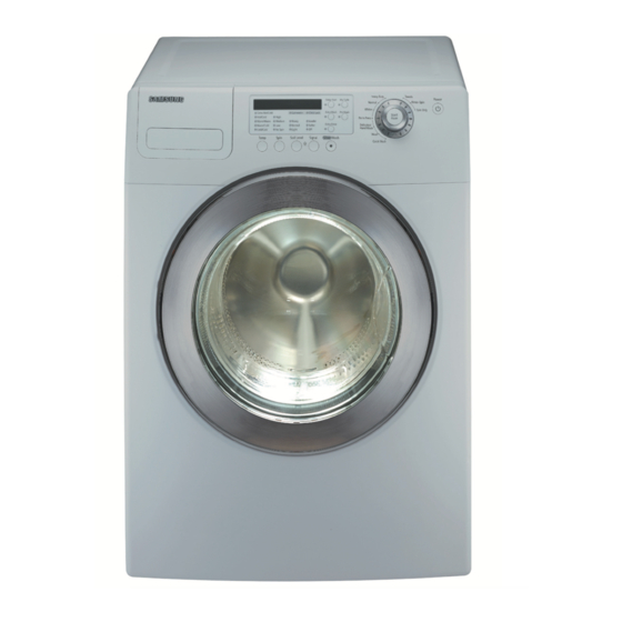
WASHING AND HEATING POWER CONSUMPTION SPIN DRAIN WF326 * SPIN REVOLUTION WF316 * WF306 * FRONT LOADING WASHER Inches (cm) 38 (96.5) C. Depth With Door Open 90° 27 (68.6) D. Depth 50 kPa ~ 800 kPa 89.9 kg 3.29 Cu.ft... - Page 12 2-2. OVERVIEW OF THE WASHING MACHINE Hot water supply hose Detergent drawer Control panel Door Cold water supply hose Drain Hose Adjustable leg...
-
Page 13: The Comparative Specifications Of Product
2-3. THE COMPARATIVE SPECIFICATIONS OF PRODUCT Samsung Item (WF316LAW) Capacity (Cu.ft) 3.29 (DOE) Volume of Spinner (ℓ) 93.4 Motor Direct Drive User Interface Cycle Time Wash Performance 1.01 Water Consumption/Cycle 48 Liter Energy Consumption (W/O Heater Wh/Cycle) 1,100 Noise 57 dB... -
Page 14: Option Specifications
2-4. OPTION SPECIFICATIONS Item Item Name CODE.NO Remark DC60-4014 6A SPANNER DC61-10688A HOLE COVER DC97-07126A for HOT HOSE DRAIN DC97-07127A for COLD MANUAL-BOOK DC68-02291A... - Page 15 Memo...
-
Page 16: Overview Of The Control Panel
Medium - Use for jeans,wrinkle-free or wash-and-wear items and synthetics. Low - Use for delicate items needing a slow spin speed because of fabric and construction. No Spin - Drains your Washer without spinning.Use for extremely delicate items that cannot tolerate any spin. 4. Soil Level selection button Press the button to select the Soil Level/washing time. - Page 17 Press to pause and restart programs. 10. Power button Press once to turn your Washer on, press again to turn your Washer off. If your Washer is left on for more than 10 minutes without any buttons being touched, the power automatically turns off.
-
Page 18: Programme Chart
3-2. PROGRAMME CHART 326LAW, 326LAS Functions Temp Spin H/C W/ C/C EH Heavy √ √ √ √ √ Duty Normal √ √ √ √ √ √ √ √ √ √ Whites √ √ √ Perm Press Delicates/ √ √ √ Hand Wash √... - Page 19 3-2. PROGRAMME CHART 316LAW, 316BAW, 316BAC Functions Temp W/C C/ Heavy Duty √ √ √ √ Normal √ √ √ √ Whites √ √ √ √ √ √ √ Perm Press √ √ √ Delica-tes/ Hand Wash √ Wool √ √...
-
Page 20: Main Function
You can add or take laundry items even after the wash has started, as long as the Garment+ light is on. Pushing the Start/ Pause button unlocks the door, unless the water is too hot or if there is too much water in your Washer. If you are able to unlock the door and wish to continue the wash cycle, close the door and press the Start/Pause button. -
Page 21: For Silvercare Washing
LU1 :between 2000 to 2999 times LU0 :over 2999 times You should replace the silver kit when it display “LU0”. Contact 1-800-SAMSUNG. Note : For some model which has no heater if you choose SilverCare, Temp will be fixed to Cold/Cold. - Page 22 3-4. TECHNICAL POINT 1) Motor on/off time at each course Course Heavy Duty Normal Whites Perm Press Delicate/Hand wash Wool Quick Wash Towels Sanitize Bedding Rinse + Spin 2) Final dehydrating r.p.m at each course Course Heavy Duty Normal Whites Perm Press Delicate/Hand wash Wool...
-
Page 23: Technical Point
3-4. TECHNICAL POINT 3) The water supply control at each process cycle Model Process cycle Cold water 5L/min Pre Washing Cold water 10L/min + (Hot water 10L/min) Washing Cold water 10L/min Rinse Cold water 10L/min + Cold water 5L/min Final rinse 4) The water level data at each course Model Course... - Page 24 Memo...
-
Page 25: Alignment And Adjustments
It is to inform the user of power failure.) Suds is detected during the washing session. (“SUdS” is not SUdS an error. If the washer is in suds period, “SUdS” will light up instead of remaining time.) Description Go to “... -
Page 26: Test Mode
Test Mode : Each Test Mode for the Frontier Washer is as follows in the coming pages. The test modes indicated by the red arrows are the modes unable to get an access once the washing cycle has started due to safety reasons. - Page 27 4-2-1. Quick Test Mode Water Valv e Test: Water Valve Test: 1. To enter the Water Valve Test, press theTemp Key while model information is being display ed during the Quic k 1. To enter the Water Valve Test, press the Temp Key while model information is Test Mode.
- Page 28 4-2-2. EEPROM Reset Mode Definition of EEPROM Reset Mode: - EEPROM initialization. - All course/option settings are to be reset to default values after EEPROM initialization. - When Service arises and it needs PCB replacement, EEPROM should be reset. How to Enter: - The unit needs to be on.
- Page 29 4-2-4. Special Test Mode Special Test Mode: 1. The washer must be on to go into the Special Test Mode. 2. The motor speed will be displayed when started (It displays 0 when the motor does not spin). 3. The present state of the machine will not be changed.
- Page 30 4-2-6. Cycle Count Check Mode Definition of Cycle Count Check Mode: - Cycle Count Check Mode is to tally up the number of washings. How to Enter: - To enter the Cycle Count Check Mode, press the Signal Key during Special Test Mode. (same for all Frontier models.) Cycle Count Check Mode: Activate the Special Test Mode in advance.
- Page 31 4-2-8. Fast Time Down Test Mode Definition of Fast Time Down Test Mode: - Fast Time Down Test Mode is to forward the program to the next cycle stage. How to Enter: - To enter the Fast Time Down Test Mode, press the Temp key during Special Test Mode. (same for all Frontier models.) Fast Time Down Test Mode: Activate the Special Test Mode in advance.
- Page 32 4-2-9. Board Input Test Mode Definition of Board Input Test Mode: - Board Input Test Mode is to displays a specified input after a key press. How to Enter: - To enter the Board Input Test Mode, press the Extra Wash key during Special Test Mode. (same for all Frontier models.) Board Input Test Mode: 1.
- Page 33 4-2-10. Diagnostic Code Check Mode Definition of Diagnostic Code Check Mode: - Diagnostic Code Check Mode is to bring up the stored diagnostic codes (reference codes for service technicians). How to Enter: - To enter the Diagnostic Code Check Mode with code “d” flashing, press the Silver Wash (Rinse Water +) during Special Test Mode.
- Page 34 Memo 4-10...
-
Page 35: Assembly And Disassembly
5. ASSEMBLY AND DISASSEMBLY 5-1. TOOLS FOR DISASSEMBLY AND ASSEMBLY TOOL Box driver 10mm 13mm 19mm Double-ended 10, 13,19mm spanner Vice pliers Other(Driver, Nipper, Long nose) JIG for the Tub Heater (1) Motor (1), Balance (5), 2 holes of each left and right of the shock absorber 1 Pulley hole Replaceable for the box driver. -
Page 36: Disassembly
5-2. DISASSEMBLY Warning! To avoid risk of electrical shock, personal injury or death, disconnect the power to the washing machine. Part Name Descriptive Picture Top Cover Water Level Sensor Ag Kit How To Do 1. Unplug the unit. 2. Remove screws(2ea) at the back. 3. -
Page 37: Assembly
5-2. DISASSEMBLY Descriptive Picture Part Name Ag PCB EMI Filter Water Valve Dispenser How To Do 1. Unplug the unit. 2. Remove Top Cover. 3. Flip open the PCB cover. 4. Disconnect the wire harness. 5. Remove screws (2ea) on the frame. 1. - Page 38 5-2. DISASSEMBLY Part Name Descriptive Picture Console Door Front Panel Boot How To Do 1. Unplug the unit. 2. Remove Top Cover. 3. Remove Dispenser Drawer. 4. Remove screws(3ea) on the top. 5. Plug out all the connectors. 6. Unscrew(6ea) PCB and separate it from Console.
- Page 39 5-2. DISASSEMBLY Part Name Descriptive Picture Heater Motor Drain Pump How To Do 1. Unplug the unit. 2. Knock the unit down to Front Panel (included). 3. Remove the wire connectors. 4. Remove the nut (10mm) in the center and take out Heater.
- Page 40 5-2. DISASSEMBLY Descriptive Picture Part Name Outer Tub and Spinner(1) How To Do 1. After the above knock-down to Drain Pump, do the following. 2. Remove screws holding the wire harness. 3. Remove the bolts (2ea,13mm) securing Rear Struts to Cabinet Bottom. 4.
- Page 41 Memo...
-
Page 42: Trouble Shooting
6. TROUBLE SHOOTING 6-1. TROUBLE DIAGNOSIS As the micom wash machine is configured of the complicate structure, there might be the service call. Below information is prepared for exact trouble diagnosis and suitable repair guide. Caution for the Repair and Replacement Please follow below instruction for the trouble diagnosis and parts replacement. -
Page 43: Will Not Spin
• Close door and push the Start/Pause key to run the washer. • Check if washer is in a pause, soak or suds process. Wait briefly and it may start. (If the washer is in suds period, Suds will light up instead of remaining time.) • Check for restricted drain system. -
Page 44: No Water Fill
6-1. TROUBLE DIAGNOSIS No Water Fill • Perform Quick Test Mode. Check all of Water Valves visually. (Pre Wash Valve, Cold Water Valve, Bleach Water Valve, Softener dispenses using Cold & Bleach Water Valve, and Hot Water Valve.) • Check if water taps are turned on fully. •... - Page 45 Also check water heater capacity and recovery rate. • If the water heater is located far from the washer, screw out the hot water tap and let its water pass until you get hot water. • Too Hot/Too Cold: Reduced amount of water is supplied while PCB controls the influx to regulate the actual temperature of the water in the tub.
-
Page 46: Buttons Do Not Respond
Rubber Feet Leaving Marks on Floor • Use a pencil eraser to remove mark. • Walk washer into location, do not drag. Additive Cups Full of Water • Small amount of water in bottom of additive cups is normal. •... -
Page 47: Problem Checking And Method Of Pcb
6-2. PROBLEM CHECKING AND METHOD OF PCB -If you plug in the power cord and turn Power S/W on, memorized data is displayed. If any data is not displayed, check the followings. 倫 倫 倫 倫 CNw CNw 塁 塁 塁 塁 倫... - Page 48 Memo...
-
Page 49: Exploded View And Parts List
7. EXPLODED VIEW AND PARTS LIST 7-1. THE CONTROL PARTS 15 42 CODE NO. DESCRIPTION DC64-01106A KNOB-ENCODER DC97-10795A ASSY-PANEL CONTROL DC64-01050A PANEL-CONTROL DC64-01105A BUTTON-PUSH(P) DC64-01126A INLAY-PANEL DC64-01112A WINDOW-ENCODER DC66-00413A LEVER-POWER MFS-F2WLHA-T0 ASSY PCB PARTS(M) MFS-FTWTHA-00 ASSY PCB PARTS(M) MES-AG3MOD-S2 ASSY PCB PARTS(S) MFS-MEMS-00 ASSY PCB PARTS(S) MFS-F2WLHA-S0... - Page 50 7-2. THE DOOR PARTS CODE NO. DESCRIPTION 6002-000444 SCREW-TAPPING 6002-000444 SCREW-TAPPING 6002-000444 SCREW-TAPPING 6002-001374 SCREW-TAPPING 6002-001374 SCREW-TAPPING 6002-001374 SCREW-TAPPING DC64-00504A DOOR-GLASS 6002-001376 SCREW-TAPPING 6002-001376 SCREW-TAPPING 6002-001376 SCREW-TAPPING 6002-001376 SCREW-TAPPING 6002-001376 SCREW-TAPPING 6002-001376 SCREW-TAPPING DC63-00673A COVER-DOOR DC64-01120A DOOR-SAFETY 6002-001279 SCREW-TAPPING DC61-01520A HOLDER-GLASS DC66-00326A LEVER-DOOR...
- Page 51 7-3. THE TUB PARTS CODE NO. 6002-001373 SCREW-TAPPING 6002-001374 SCREW-TAPPING 6011-001554 BOLT-ETC 6011-001559 BOLT-HEX DC31-00049A MOTOR-DRUM DC47-00006G HEATER DC60-50148B NUT-HEX DC60-60044A WASHER-PLAIN DC60-60044A WASHER-PLAIN DC60-60044A WASHER-PLAIN DC60-60049A WASHER-SPRING DC61-01257A SPRING-HANGER DC67-00139A WEIGHT-BALANCER(F) DC97-02412F ASSY-BOLT DC97-10337A ASSY-DRUM 6011-001491 BOLT-FLANGE DC66-00386A DRUM-FRONT...
-
Page 52: Assy-Cover Top
7-4. THE FRAME PARTS 36 60 15-6 15-5 15-3 15-1 15-4 15-2 15-9 ( ASSY-PUMP DRAIN ) 19-3 19-1 19-2 19-4 ( ASSY-ABSORBER ) CODE NO. DESCRIPTION 6002-001374 SCREW-TAPPING 6002-001374 SCREW-TAPPING 6002-001374 SCREW-TAPPING 6002-001376 SCREW-TAPPING 6002-001376 SCREW-TAPPING 6002-001376 SCREW-TAPPING 6002-001376 SCREW-TAPPING 6009-001458 SCREW-SPECIAL... - Page 53 Memo...
-
Page 54: Electrical Parts List
8. ELECTRICAL PARTS LIST -You can search for updated part codes through ITSELF web site. URL : http://itself.sec.samsung.co.kr/ Level CODE NO. DESCRIPTION 6001-001773 SCREW-MACHINE 6002-000444 SCREW-TAPPING 6002-001374 SCREW-TAPPING 6002-001376 SCREW-TAPPING 6003-001563 SCREW-TAPTITE 6009-001476 SCREW-HEX DC63-00522A COVER-BACK DC97-04973A ASSY-WIRE DIAPHRAGM DC97-07448A... - Page 55 8. ELECTRICAL PARTS LIST Level CODE NO. DESCRIPTION MFS-MEMS-00 ASSY PCB PARTS(S) DC63-00693A COVER-DOOR SWITCH 6002-001373 SCREW-TAPPING 6002-001374 SCREW-TAPPING 6011-001554 BOLT-ETC 6031-001523 WASHER-WAVE DC31-00049A MOTOR-DRUM DC47-00006G HEATER DC60-50148B NUT-HEX DC60-60044A WASHER-PLAIN DC60-60049A WASHER-SPRING DC67-00139A WEIGHT-BALANCER(F) DC97-02412F ASSY-BOLT DC97-03716C ASSY-SENSOR PRESSURE ...3...
- Page 56 ASSY POWER CORD DC96-00774A ASSY-PUMP DRAIN ...3 6002-001376 SCREW-TAPPING ...3 DC62-00202A VALVE-CHECK ...3 DC61-01424A BRACKET-PUMP ...3 DC99-00704A ASSY-CUSHION PUMP ...4 6031-001531 WASHER-PLAIN ...4 DC63-00619A CUSHION-PUMP DC96-01043A ASSY-M.WIRE HARNESS DC97-06995A ASSY-FRAME DC97-07128D ASSY-HOSE DRAIN(I) ...3 DC61-00219C CLIP-HOSE ...3 DC62-10022G HOSE-PUMP DC97-08740C ASSY-CAP O.F...
- Page 57 8. ELECTRICAL PARTS LIST Level CODE NO. DESCRIPTION ...5 0401-000005 DIODE-SWITCHING ...5 0601-001028 ...5 0601-001751 ...5 1003-000337 IC-DARLINGTON DRIVER ...5 2003-000642 R-METAL OXIDE(S) ...5 2202-002037 C-CERAMIC,MLC-AXIAL ...5 3404-001022 SWITCH-TACT ...5 3711-000651 HEADER-BOARD TO CABLE ...5 3711-003133 HEADER-BOARD TO CABLE ...5 DC07-00038A LED DISPLAY ...5...
- Page 58 8. ELECTRICAL PARTS LIST Level CODE NO. DESCRIPTION ...5 0402-000351 DIODE-RECTIFIER ...5 0402-001194 DIODE-RECTIFIER ...5 0402-001404 DIODE-BRIDGE ...5 0403-000537 DIODE-ZENER ...5 0501-000316 TR-SMALL SIGNAL ...5 0504-001080 TR-DIGITAL ...5 0604-000118 PHOTO-COUPLER ...5 0801-000168 IC-CMOS LOGIC ...5 1103-001183 IC-EEPROM ...5 1202-000001 IC-VOLTAGE COMP..5 1404-000230 THERMISTOR-PTC...
- Page 59 8. ELECTRICAL PARTS LIST Level CODE NO. DESCRIPTION ...5 2802-001202 RESONATOR-CERAMIC ...5 3002-001080 BUZZER-PIEZO ...5 3501-001154 RELAY-MINIATURE ...5 3501-001269 RELAY-POWER ...5 3501-001272 RELAY-POWER ...5 3601-001168 FUSE ...5 3711-000833 HEADER-BOARD TO CABLE BOX,2P,1R,8MM,STRA ...5 3711-004783 HEADER-BOARD TO CABLE BOX,8P,2R,4.2mm,ST ...5 3711-004929 HEADER-BOARD TO CABLE BOX,3P,1R,10MM,STR ...5 3711-005680...
- Page 60 8. ELECTRICAL PARTS LIST Level CODE NO. DESCRIPTION ...3 2001-000429 R-CARBON ...3 2001-000734 R-CARBON ...3 2003-000616 R-METAL OXIDE(S) ...3 2006-001083 R-CEMENT ...3 2201-000153 C-CERAMIC,DISC ...3 2201-000879 C-CERAMIC,DISC ...3 2202-002037 C-CERAMIC,MLC-AXIAL ...3 2401-000455 C-AL ...3 2401-000598 C-AL ...3 2001-000429 R-CARBON ...3 2001-000734 R-CARBON ...3...
- Page 61 8. ELECTRICAL PARTS LIST Level CODE NO. DESCRIPTION DC97-07130A ASSY-TUB BACK ...3 6011-001553 BOLT-ETC ...3 6601-001207 BEARING-BALL ...3 6601-001208 BEARING-BALL ...3 DC97-08649A ASSY-SEMI TUB BACK ...4 DC61-01174A TUB-BACK ...5 0103-002522 RESIN-FRPP ...4 DC61-40348B BRACKET-NUT ...4 DC68-02060A LABEL-TUB ...4 DC97-06991A ASSY-HOUSING BEARING ...5 6601-001338 BEARING-BALL...
- Page 62 8. ELECTRICAL PARTS LIST Level CODE NO. DESCRIPTION DC72-00013D SPONGE-HARNESS ...3 6002-001294 SCREW-TAPPING ...3 DC31-00054A PUMP-DRAIN ...3 DC61-01254A CASE-PUMP ...3 DC72-00034E SPONGE-EPDM ...3 6041-001035 RIVET-RH ...3 DC61-01180A FRAME ...4 DC61-01405A PLATE-STEEL ...3 DC61-01182B BRACKET-SPRING(L) ...3 DC61-01183B BRACKET-SPRING(R) ...3 DC97-06994A ASSY-PLATE BOTTOM ...4 DC61-01181A PLATE-BOTTOM...
- Page 63 Memo 8-10...
-
Page 64: Block Diagram
9. BLOCK DIAGRAM... - Page 65 Memo...
-
Page 66: Wiring Diagram
10. WIRING DIAGRAM 10-1... - Page 67 Memo 10-2...
-
Page 68: Pcb Diagram
11. PCB DIAGRAM 11-1 MAIN PCB LAYOUT Item Part Number Description Displays or indicates opera- Display tions or functions Starts/stops an operation to Jog_Dial select a course Power_key Turns the power on/off Selects and processes each function Detects if the door is open or closed In case of Power_On/Off, RELAY1... - Page 69 11-2 Connector & Relay Terminals Description (MAIN PCB) RELAY1 A)Connects to AC2 B)Connects to AC2-1 COMMON RELAY2 A)Connects to the HEATER B)Connects to the HEATER A)Connects to the DOOR LOCK Signal B)Connects to the DOOR LOCK Signal ②Connects to AC1 ③Connects to GROUND ①Connects to the MOTOR STATOR ③Connects to the MOTOR STATOR...
- Page 70 11-3 Connector & Relay Terminals Description (AG-KIT PBA) ①Connects to AC1 ③Connects to AC2 ①Connects to GORUND ②Connects to IH ③Connects to PWM ④Connects to SIGNAL-B ⑤Connects to SIGNAL-A ⑧Connects to AG-B ⑨Connects to AG-A 11-3...
- Page 71 Memo 11-4...
-
Page 72: Schematic-Diagrams
12. SCHEMATIC DIAGRAMS 12-1. Main PCB * This Document can not be used without Samsung’s authorization. 12-1... - Page 73 12-2. SUB PCB * This Document can not be used without Samsung’s authorization. 12-2...
- Page 74 12-3. MEMS PCB * This Document can not be used without Samsung’s authorization. 12-3...
- Page 75 12-4. AG PCB * This Document can not be used without Samsung’s authorization. 12-4...
-
Page 76: Circuit Descriptions
13. CIRCUIT DESCRIPTIONS 13-1. OVERALL SYSTEM 13-1... - Page 77 13-2. AC Input & Power Circuit ▶ Function Generates a required DC power of 12V or 5V in case of supplied or disconnected AC power. ▶ Description - When AC 220V is applied to CN3, D17 D20 transforms it to DC 300V. - DC 300V is generated for the LVT1 secondary source by IC3 and PC1 turning on/off.
- Page 78 13-3. Driving System Circuit ▶ Function Controls each driving system (VALVE, DOOR S/W, DRAIN-MOTOR) by turning RELAY or TRIAC on/off. ▶ Description - MICOM outputs a high signal of 5V from pin # 1 - 7 of IC7 and IC9. - Then, pin # 10 to 16 of IC7 and IC9 are electrically grounded (0V).
- Page 79 13-4. Sensor Detection Circuit ▶ Function Detects signals from the sensor and controls the current system. ▶ Description - The water level sensor is connected to pin 4 of CN7. - The frequency of the level sensor changes according to the water amount in the tub. - Then, the frequency is input to MICOM pin 48 for detecting the water amount.
- Page 80 13-5. Silver Nano System ▶ Function Applies the electric current to the silver plate during the water supply and uses the silver water to perform the bacteria-free or sterilization processes. ▶ Description - Selects the silver nano feature to operate the system. - Supplies water to the two silver plates AG_B and AG_A.
- Page 81 Memo 13-6...
-
Page 82: Reference Information
14. REFERENCE INFORMATION 14-1. MODEL NAME 14-1... -
Page 83: Terminology
14-2. TERMINOLOGY ASSY-MAIN PCB (Imbalance Sensor) → To prevent the laundry from gathering on one side of the tube causing noise and vibration, the washing machine uses an imbalance detection device that evenly disentangles the laundry before the hydrating cycle starts. DOOR-LOCK S/W →... -
Page 84: Fabric Care Chart
40° F/4° C which is too cold for effective cleaning. The water temperature in this situation will need to be adjusted by selecting a warm setting, adding some hot water to the MAX FILL line or using your Washer’s heating option, if available. -
Page 85: Electrical Warnings
14-4. ELECTRICAL WARNINGS To reduce the risk of fire, electrical shock, and other injuries, keep these safety precautions in mind: Operate the appliance only from the type of power source indicated on the marking label. If you are not sure of the type of power supplied to your home, consult your appliance dealer or local power company. -
Page 86: Q & A
Power button may have been accidentally bumped or pushed. Reset the cycle and start the washer. Make sure the unit is plugged into a live electrical outlet. Check house fuse or circuit breaker. - Page 87 Memo 14-6...
- Page 88 Be Aware, Be Alert Always work safely. On the Job, On the Road, In the Home Every Time, All the Time...