Advertisement
Quick Links
Advertisement

Related Manuals for MD SPORTS 1544125


Summary of Contents for MD SPORTS 1544125
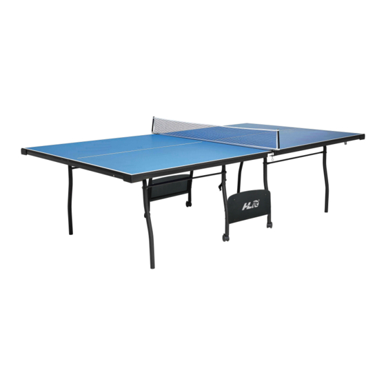
- Page 1 TABLE TENNIS TABLE Assembly Instructions SUT-9F04HW...
- Page 2 1. It is important to read the manual before assembling and using the games table. Safe and effective use can only be achieved if the table is assembled, maintained and used properly. It is your responsibility to ensure that all users of the equipment are informed of all warnings and precautions.
- Page 3 95918-UK PARTS LIST / TEILELISTE Table Surface - 2 Table Surface - 1 Wrench Allen Key Curved Outer Leg Linkage Tube Curved Inner Leg Linkage Tube with Stop Bracket with Cap with Cap Side Panel End Panel Gravity Lock Bracket (1.25m) (1.35m) Safety...
- Page 4 FIG. 1 FIG. 1A X 27 FIG.1 1. Place Table Surface - 1 (#1) and Table Surface - 2 (#2) with the painted surface facing down on a soft flat surface. 2. Connect Table Surfaces together using three Brackets (#9) using twelve Screws (#29). See FIG. 1 and 1A 3.
- Page 5 FIG. 2 FIG. 2A X 64 FIG.2 4. Place one Curved Outer Leg with Cap (#5) on the player end of the table half and one Curved Inner Leg with Cap (#6) on the center end of the table half. 5.
- Page 6 FIG. 3A FIG. 3 X 16 FIG. 3B FIG.3 7. Attach one end of the Linkage Tube (#8) to the inside of the Curved Outer Leg (#5) using one Bolt (#24), two Washers (#26), one Spacer (#27) and one Nut (#28). See FIG. 3A. 8.
- Page 7 FIG.4A FIG. 4 X 44 FIG.4 12. Place Plastic Corners (#17) flush with table corners, using three Screws (#23) per Corner. See FIG. 4A. 13. Place the End Panel (#11) between the corners and flush with the table edge at the Player end of table using six Screws (#23) per End Panel.
- Page 8 FIG. 5 FIG.5 15. Make sure the Outer Leg Caps (P1) and Inner Leg Caps (P2) are installed into the ends of the leg. Then place the Wheel (#18) into the Legs. See FIG. 5. 16. Attach the Logo Panel with Frame (#21) to the Curved Inner Leg (#6) using two Bolts (#25), four Washers (#26) and two Nut (#28) per Frame.
- Page 9 Warning FIG. 6 FIG. 6B FIG. 6A FIG. 6D FIG. 6C B. FOLD LEGS AND C. LIFT TABLE AND D. DO NOT LEAN E. SET TABLE DOWN TABLE HALVES AND TURN IN THE AIR TABLE ON ITS LEGS! EVENLY ON ALL A.
- Page 10 FIG. 7 Nota: La tolerancia de la distancia central está aproximadamente de 10~13mm. FIG.7 17. Before turning the table over, you must push the Curved Inner Leg (#6) in towards the center of the table in order to fix the leg in the right position. NOTE: Two adults are required to turn this table over. 18.
- Page 11 FIG. 8 FIG. 8A FIG.8 21. Attach one Gravity Lock (#10) to the Curved Inner Leg (#6) using one Bolt (#24), two Washers (#26), one “T” Washer (#22) and one Nut (#28) per Gravity Lock. See FIG. 8A.
- Page 12 FIG. 9 FIG.9 22. Attach the Net Post (#16) at the middle of the table and slide the net over the post. Stretch the Net (#15) across the center of the table and slip the net over the post on the opposite side. See FIG. 9A.
- Page 13 FIG. 10A FIG. 10 FIG. 10B FIG. 10D FIG. 10C Safety Straps FIG.10 23. Engage the Wheels Lock. 24. Folding the table - First fold the side of the table without the Net Post. Hold the end securely and lift the table.