
Related Manuals for Danfoss PVED-CLS


Summary of Contents for Danfoss PVED-CLS
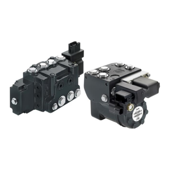
- Page 1 ENGINEERING TOMORROW PVED-CLS Controller For Electrohydraulic Steering User Manual Software version 2.01...
- Page 2 ENGINEERING TOMORROW Important User Information Danfoss is not responsible or liable for indirect or consequential damages resulting from the use or application of this equipment. The examples and diagrams in this manual are included for illustration purposes. Due to the many variables and requirements associated with any particular installation, Danfoss cannot assume responsibility or liability for the actual used bases on the examples and diagrams.
- Page 3 OSPE Steering valve, SASA sensor, Technical Information PVED-CLS Communication Protocol PVED-CLS KWP2000 Protocol PVED-CLS Safety Manual PVED-CLS Technical Information EHi Technical Information Operating/Safety Manual for J4F with 351JCM Definitions and Abbreviates µC Micro-Controller © Danfoss | August 2018 AQ00000211 | 3...
- Page 4 EHPS Electro-Hydraulic Power Steering Fault Detection Algorithm FIFO-principle First-in-first-out-principle Failure Mode Identifier Guidance Machine Status Global Positioning System and Danfoss “short call-name” for Auto- guidance Internal Monitoring Disengage Internal Resolution [0.1%] ISOBUS Communication Protocol (ISO 11783) KWP2000 Keyword Protocol 2000...
- Page 5 Unsigned - 16 bit Unsigned - 8 bit Voltage - Direct Current Wheel Angle Sensor x 10u Meter times 10 micro-meter x100msec times 100 milliseconds x10mSec times 10 milliseconds Extended Message Identifier © Danfoss | August 2018 AQ00000211 | 5...
- Page 6 ENGINEERING TOMORROW 6 | © Danfoss | August 2018 AQ00000211...
-
Page 7: Table Of Contents
EHPS System ................................... 16 PVED-CLS FUNCTIONAL OVERVIEW ......................18 PVED-CLS system overview ............................. 18 PVED-CLS steering mode selection state machine ....................19 Steering wheel state machine ............................. 20 AUX steering state machine ............................... 21 Auto-guidance steering state machine ..........................21 State transition requirements description ........................ - Page 8 Anti-jerk ..................................... 89 10.6 Calculation of flow set-point using anti-jerk functionality ..............90 10.6.1 Soft-stop ..................................... 93 10.7 AUX STEERING ............................... 95 Block diagram ..................................96 11.1 Open loop mini-wheel ............................96 11.1.1 8 | © Danfoss | August 2018 AQ00000211...
- Page 9 Parameter Cross Check ............................... 139 17.1 Error codes ....................................142 17.2 FMI list ..................................... 148 17.3 Parameter list ..................................148 17.4 Hydraulic config ..............................149 17.4.1 SEHS FDA ................................150 17.4.2 Valve Calibration ..............................151 17.4.3 © Danfoss | August 2018 AQ00000211 | 9...
- Page 10 Determining the open loop dead-bands ..............177 Calibration procedure ......................178 Closed loop dead-band calibration ................179 Open loop dead-band calibration.................180 Determining TL and TR for a specific vehicle type ..........180 Post conditions .............................181 17.6.5.3 10 | © Danfoss | August 2018 AQ00000211...
-
Page 11: General Information
Increasing demand shows a trend for a higher safety-level up to AgPl “d” for off-road driving. In order to give this functionality Danfoss has developed the PVED-CLS. The PVED-CLS is based on Danfoss PVE technology, as used in electro hydraulic proportional valves for decades. PVE modules are used with PVG spool valves and dedicated spool valves for steering applications, OSPE and EHPS as well as the EHi-E and EHi-H systems. -
Page 12: Can Interface
Missing curvature commands are exceptions and does not put PVED-CLS to safe state. A reset may be either a power cycle sequence or a soft reset CAN message. For more details, please see the Danfoss document- PVED-CLS communication Protocol. -
Page 13: System Overview
AD3 (not used) valve EH valve LVDT 5V sensor supply + bridge Sensor ground - Main Micro-crontroller CAN_Main Main spool position PLUS+1 Service Main spool position tool PVED-CLS WAS* Figure 2 EHi-E System © Danfoss | August 2018 AQ00000211 | 13... - Page 14 Figure 3 EHi-H System In a OSPE (Figure 1) and EHi-E (Figure 2) with PVED-CLS, a Danfoss SASA-sensor and a two channel vehicle speed sensor, a MMI interface (for changing programs, steering devices, steering modes etc.) on the CAN bus are prerequisite in order to complete the OSPE and EHi-E systems.
- Page 15 Valid Values: 0 (OSPE, EHi-E); 1 (EHPS); 2 (EHi-H) OSP displacement, number of cubic centimeters per revolution OSP displacement P3084 Note: When the PVED-CLS is mounted on an EHPS this parameter must be set equal to 0! Cylinder stroke volume. Acceptable values: 100-10000.
-
Page 16: Ehps System
When the PVED-CLS is mounted on an EHPS the cut-off valve is not present, therefore P3072 needs to be 0 and the valve type needs to be set to EHPS by setting P3081 to 1. Furthermore, as the flow direction in an EHPS compared to OSPE/EHi- E and EHi-H is inverted, the PVED-CLS need to be provided with this information, which can be done by setting P3080 to 255. - Page 17 (hence pure hydraulic Resolution: 0.01 turns) OSP displacement, number of cubic centimeters per revolution OSP displacement P3084 Note: When the PVED-CLS is mounted on an EHPS this parameter 1200 must be set equal to 0! Cylinder stroke volume. Acceptable values: 100-10000.
-
Page 18: Pved-Cls Functional Overview
- Anti-jerk, chapter 10.6 scaling, chapter 11.8 - Closed loop joystick – vehicle speed dependent wheel angle limitation, chapter 11.10 - Closed Loop Joystick –vehicle speed dependent closed loop control, chapter 11.11 18 | © Danfoss | August 2018 AQ00000211... -
Page 19: Pved-Cls Steering Mode Selection State Machine
Figure 5 shows the high level steering mode selection state machine. The state transition requirements are described in detail in chapter 3.6. The operational states of PVED-CLS can be observed in ‘Operation status message’, (refer PVED-CLS Communication Protocol document for more details). -
Page 20: Steering Wheel State Machine
P3254 (SASA or IMD), the further transition of states is determined for steering with SASA or steering with IMD. In Steering wheel program 1 – 5, the EH-Valve is active and the PVED-CLS behavior can be configured individually. Find additional information on how to setup the programs in chapter 10. -
Page 21: Aux Steering State Machine
Figure shows the AUX steering device state machine. When the AUX device is configured to be a steering wheel, PVED-CLS offers 5 individually configurable steering programs. If the AUX device is configured to be a joystick, only 1 program is available. Find more information regarding AUX devices and the configuration in chapter 11. - Page 22 Machine can execute commands: System is not ready invalid command Machine system lockout: Inactive From selected auto- Guidance limit status: not limited guidance controller: Guidance exit reason: Remote command out of range/invalid INVALID_COMMAND on time AND GPS_EN Figure 8 22 | © Danfoss | August 2018 AQ00000211...
- Page 23 Steering input position status: Correct position Machine can execute commands: System is ready Machine system lockout: Inactive Guidance limit status: Provided by GPS control algorithm Guidance exit reason: Normal Operation Figure 10 © Danfoss | August 2018 AQ00000211 | 23...
-
Page 24: State Transition Requirements Description
The PVED-CLS detects the AUX open loop device to be in use when, The AUX steering device is present in the system – P3239 set to 255 The AUX steering device is enabled – see flags in the MMI messages in PVED-CLS communication protocol, 1. - Page 25 The PVED-CLS detects the AUX closed loop joystick to be enabled when, The AUX steering device is present in the system – P3239 set to 255 The AUX steering device is enabled – see flags in the MMI messages in PVED-CLS communication protocol, The AUX steering device is a closed loop joystick –...
-
Page 26: Auto-Guidance Related Conditions
- Max. CL steady state error threshold) for at least the time specified threshold value for P3731 (AUX joystick - Min time for CL steady state error threshold) The closed loop joystick is inactive – see flags in the AUX messages in PVED-CLS communication protocol 3.6.3... -
Page 27: Vehicle Speed Dependent Conditions
|Vehicle Speed| ≤ threshold value for P3251 (Max vehicle speed for program changes) 3.6.5 Other conditions • OFF_ROAD (In Off-road steering mode) The system is in the Normal Operation state and in the Off-road steering mode. See additional info in chapter 7.7 © Danfoss | August 2018 AQ00000211 | 27... -
Page 28: Parameter Configuration
Table 3 Attention Unlock codes, for the different user levels, are managed by Danfoss technical support team and can only be aquired by directly contacting the Danfoss technical support team! Danfoss has developed a service tool (PLUS+1 SERVICE TOOL), and recommend the tool for: •... - Page 29 Test Automatic spool calibration and verify safety setup of vehicle For learning more of how the PLUS+1 SERVICE TOOL works, please go to the Danfoss Power Solution home page. For using other tools than PLUS+1 SERVICE TOOL to manually changing parameters and updating sector- and signature CRC’s in the EEPROM, please refer to the Danfoss document: PVED-CLS KWP2000 Protocol.
-
Page 30: Installation
ENGINEERING TOMORROW Installation CONNECTOR INTERFACE The PVED-CLS is only available with one connector variant: 12 pin Deutsch DT04-12PA-B016 connector Figure 11 Important Deutsch assembly and installation guidelines must be followed for connector and harness. Accordingly, Danfoss recommends the use of lubricant (e.g. Nyogel 760G) on low-voltage electrical Connector contacts to further enhance the robustness against wear (e.g. -
Page 31: Pved-Cls Led Diagnostic
ENGINEERING TOMORROW PVED-CLS LED DIAGNOSTIC The PVED-CLS is equipped with a LED (see Figure 12). The LED behavior will inform about the state of the PVED- CLS: State LED behavior Main µC in the bootloader mode Blinking between or Main µC detects the Safety µC in the bootloader mode... -
Page 32: Mapping A Steering Device/Sensor
Section 8.1 and section 8.1.1. The wheel angle sensor sub-system can be CAN based or Analogue based. If it is analogue based, WAS may be connected to the analogue input pins of the PVED-CLS; AD1 and AD2 for analogue dual channel sensor sub-system and AD1 for single channel sensor sub-system. - Page 33 Table 5 When mapping a steering device or sensor, the CAN source addresses (Table 6) and PGN’s (Table 7) needs to be set up and checked for correctness. Find additional information about setting up the CAN communication in PVED-CLS communication protocol.
- Page 34 PGN for Aux Elobau Joystick- PGN for AUX Elobau P3329 PGN' values for BJM1,BJM2,EJM1 and EJM2 are 64982,64984,64983 65535 64982 joystick and 64985 respectively. Table 7 Default Values for Safety controller 34 | © Danfoss | August 2018 AQ00000211...
-
Page 35: Hydraulic And Peripherals Config
• For more details and wiring schematics, please referrer to the PVED-CLS Safety Manual. • If the PVED-CLS is mounted on a EHPS valve, P3072: Cut-off valve present must be set to 0 (Not present), as the EHPS valve does not have a cut-off valve. If P3072: Cut-off valve present is set to any other value than 0 (Not present), the PVED-CLS enter safe state. - Page 36 ON-OFF control mode, i.e. P3073: Cut-off valve control mode is set to 0 This control algorithm will set the duty cycle of the PWM signal to 100%, when the PVED-CLS is activating the cut-off solenoid valve, this means that the power supply of the cut-off solenoid valve will be equal to the PVED-CLS power supply.
- Page 37 ����3097 = 12 ���� = 0,5 For this example, P3097: Cut-off valve PWM pre-load value must be set to 50 (50%), to avoid the PVED-CLS from triggering safe state due to overcurrent in the solenoid. © Danfoss | August 2018...
-
Page 38: Cut-Off Valve Monitoring
ENGINEERING TOMORROW Important There is no validation in the PVED-CLS that P3074: Cut-off valve CL pull current > P3076: Cut-off valve CL hold current. Important Danfoss recommends not to change the default values for P3074, P3076 and P3097. Contact your local technical support at Danfoss Power Solutions if there is a need to change these parameters. -
Page 39: 7.1.2.2 Cut-Off Valve Monitoring For Ehi-H
PVED-CLS does not goes into fail safe mode in cold conditions. • If PVED-CLS is commanded to go to off-road mode before pump pressure is available, PVED-CLS will not be able to perform this self-test and hence fail after the specified timeout set by P3078. -
Page 40: Road Switch
If the fall time is observed longer than specified by P3101: Safety-checks IMD – Maximum fall time, the COV solenoid will be concluded as stuck open and the PVED-CLS will enter safe state. There is no limit on how long the rise time can This check ensures that the cut-off valve can achieve the blocked state, when the cut-off solenoid valve is de-energized. - Page 41 Important Not all combinations of these 3 parameters are valid. If an invalid condition is detected by PVED-CLS, it will enter safe state and notify about an invalid EEPROM configuration of the Peripherals sector. See truth table in Table 11.
-
Page 42: Eh Steering Disengage Method
When PVED-CLS is in Safe on-road state, this function slowly increases the duty-cycle on the cut-off output. If the current raises above the parameter threshold, specified by P3243, the PVED-CLS goes to safe, because it has detected that the Cut-off coil was not disconnected on the transition to Safe on-road thus reports a relay switch failure. -
Page 43: Valve Capacity
Important The PVED-CLS is dedicated for IMD: It has built in check valves between pilot ends of the EH spool to the PE pilot supply. In this way, its ensured there will be no hydraulic pressure on either end of the spool when the cut off spool is in safe state, because the pilot supply is connected to tank. - Page 44 B: valid for spools for nominal cylinder flow CQ = 40 l/min C: valid for spools for nominal cylinder flow CQ = 60 l/min D: valid for spools for nominal cylinder flow CQ = 80 l/min 44 | © Danfoss | August 2018 AQ00000211...
-
Page 45: Lvdt Compensation And Spool Threshold At Boot-Up
P3090. If the spool is outside this threshold during boot-up and the PVED-CLS is mounted on an OSPE/EHi, the PVED-CLS will go into safe state. If the PVED-CLS is mounted on an EHPS, further checks are done to see if the spool has moved outside the dead-band, a confidence counter level has to be reached before PVED-CLS will go into safe state. -
Page 46: Analogue Input Drift Compensation
P3248 set to 1 will shut down the sensor supply but not the monitoring of it. So if it is disabled (i.e. P3248 set to 1), an external 5V supply has to be connected to PVED-CLS sensor supply pin (pin 11) else PVED-CLS will go to safe state. -
Page 47: Steering Device And Program Changes
The complete PVED-CLS Steering mode selection state machine is shown in chapter 3.2. Similar to the steering device lock, the PVED-CLS will lock a steering program (AUX or STW), when a vehicle speed threshold of P3251 is exceeded (i.e. the PVED-CLS will ignore any steering program change messages, if the vehicle is traveling faster than the value in P3251). -
Page 48: Vehicle Geometry
P3253 indicates at which vehicle speed, the PVED-CLS should go into safe state, if this vehicle speed is exceeded during EH-steering. Important If the PVED-CLS is in Safe ON-Road mode, the PVED-CLS will not go into safe state (SVB and cut-off valve are already de-energized)! Range... - Page 49 Θ can be calculated, which is equal to P3426 when �������� steering in a circle to the left and P3428 when steering in a circle to the right. ���� = tan � � −1 ���� © Danfoss | August 2018 AQ00000211 | 49...
- Page 50 Maximum steer angle to right side Maximum steer angle, P3428 Note: Writing values >89 will force to use automatic adjusted OEM, Dealer 65535 right maximum steer angle, Right-value on WAS calibration Table 20 50 | © Danfoss | August 2018 AQ00000211...
-
Page 51: 7.10 Setup A Steering Device
For being able to start up the PVED-CLS in operational mode/off-road steering mode, the below mentioned sensors can be connected to the PVED-CLS before start-up and the WAS and spool dead-bands must be calibrated. If WAS and SASA © Danfoss | August 2018... -
Page 52: Wheel Angle Sensor
ENGINEERING TOMORROW sensors are absent, then the FDA can be disabled, to avoid PVED-CLS from going into safe state (refer chapter 14, for details on FDA). Furthermore, if the system is an OSPE/EHi-E or EHi-H system, the Cut-off valve must also be connected as a boot-up check is done on the Cut-off Valve presence. -
Page 53: Sasaiid Sensor
ENGINEERING TOMORROW SASAIID SENSOR Similar to the speed sensor, the PVED-CLS’s relies on a safe steering wheel feedback from the SASAIID sensor (not used in EHi-H system, refer section 7.1.4). The SASAIID sensor is designed to send a redundant CAN-message containing both steering wheel position and steering wheel velocity. -
Page 54: Calibration
ENGINEERING TOMORROW Calibration A PVED-CLS shall always be calibrated to the valve it is controlling (OSPE, EHPS, EHi-E or EHi-H). This allows cancellation of mechanical, electrical and environmental dependent tolerances. Spool calibration also compensates for the mechanical dead-bands designed into the EH spool. Spool calibration is only required at first installation or after PVED- CLS replacement. -
Page 55: Wheel Angle Sensor Calibration
WHEEL ANGLE SENSOR CALIBRATION As per default, a PVED-CLS will boot-up in WAS calibration service mode if P3244 i.e. WAS interface is set to either analogue or CAN. From here either WAS auto-calibration routine from the Danfoss PLUS+1 SERVICE TOOL can be used or a manual WAS calibration can be performed (see 17.6). -
Page 56: Automatic Adjustment Of Maximum Steer Angles And Cylinder Stroke Volume
• If P3426 is set to a value > 89 and if P3428 is set to a value > 89, that forces the PVED-CLS to calculate and use automatic adjusted values for Maximum steer angle, Left (i.e. P3193 or P3223 will be updated after WAS calibration, depending on WAS-type, by lookup in Table 26), and forces the PVED-CLS to calculate and use automatic adjusted values for Maximum steer angle, Right (i.e. - Page 57 < |Captured right most position – Captured neutral position|, the consistency check will fail and the WAS calibration will be aborted where; “captured right/left most position” and “captured neutral position” is the values in mVolts captured during WAS calibration, regardless if analogue or CAN based WAS is used. © Danfoss | August 2018 AQ00000211 | 57...
- Page 58 + some tolerance. Automatic adjusted cylinder stroke volume (steering left) P3819 P3817 P3815 |Captured left most position – Captured neutral position| P3821 0.33 0.67 1.00 Figure 19 58 | © Danfoss | August 2018 AQ00000211...
- Page 59 + some tolerance. Automatic adjusted cylinder stroke volume (steering right) P3827 P3825 P3823 |Captured right most position – Captured neutral position| P3829 0.33 0.67 1.00 Figure 20 Name Description of parameter Range © Danfoss | August 2018 AQ00000211 | 59...
- Page 60 |Captured left most position – Captured neutral position| P3834 0.33 0.67 1.00 Figure 21 Range Name Description of parameter WAS calibration - P3836 Mapped maximum wheel angle (steering right) at 33% voltage base OEM, Dealer Mapped max WA 60 | © Danfoss | August 2018 AQ00000211...
-
Page 61: Analogue Joystick Calibration
1.00 Figure 22 ANALOGUE JOYSTICK CALIBRATION As per default, PVED-CLS will boot-up in Analogue joystick calibration service mode after one of the below conditions is reached • If WAS interface i.e.P3244 is set to CAN AND AUX Present i.e. P3239 is set to TRUE and AUX Type i.e. P3240 is set to analogue joystick, and a successful WAS calibration has been completed. -
Page 62: Spool Calibration
SPOOL CALIBRATION As per default, a PVED-CLS will boot-up in spool calibration service mode after a successful WAS calibration, if WAS interface (i.e. P3244) is set to either analogue or CAN, has been completed. From here either the spool auto-calibration routine from the Danfoss PLUS+1 SERVICE TOOL can be used or a manual spool calibration can be performed, using the direct output control function. -
Page 63: Spool Calibration Overview
Closed loop dead-band P3168 x10u Meter Spool closed loop dead-band edge, Right OEM, Dealer edge, right Open loop dead-band P3170 x10u Meter Spool open loop dead-band offset OEM, Dealer edge offset Table 28 © Danfoss | August 2018 AQ00000211 | 63... - Page 64 Important If WAS is not configured, i.e. parameter P3244, is set to NONE, the calibration cannot be performed and PVED-CLS will signal this in the operation status message. For more details on operational status message, please see the Danfoss document- PVED-CLS communication Protocol.
-
Page 65: Auto-Calibration
B. If P3244 is set to 2, P3777 is set to 0 and P3778 set to 255. PVED-CLS will go into Spool calibration service mode if P3244 (WAS interface) is set to 1 or 0, the conditions 1A, 1B and 2A are not fulfilled, P3771 is set to 0 and P3772 is set to 255. -
Page 66: Initial Setup
Spool calibration - +/- measure the time for when moving the spool from left to right and right to P3804 dDeg OEM, Dealer turn range sweep left. Resolution: 1 dDeg 1 = 0,1°. 66 | © Danfoss | August 2018 AQ00000211... -
Page 67: Auto-Calibration Parameter Plausibility Check
“Captured neutral analogue sensor values” - “Captured rightmost analogue sensor values” ≥ P3793) Important The WAS or Joystick auto-calibration routine will return an error message if detected analogue sensor calibration values result in a too small working range. P3797, P3799: © Danfoss | August 2018 AQ00000211 | 67... - Page 68 P3801: Before automatic spool calibration can be started, the steering wheel has to be armed first. This is to tell the PVED-CLS, that grabbing the steering wheel can be detected, and thus can be used to disengage ongoing spool calibration.
- Page 69 P3808 and the spool set-point will be increased by 1 [10um], if the last attempt was slower than specified by P3806. This is repeated until a successful spool dead-band calibration has been achieved. © Danfoss | August 2018 AQ00000211 | 69...
-
Page 70: Execute Auto-Calibration From Plus+1 Service Tool
(Capture L, Capture N and Capture R) respectively. It doesn’t matter in which sequence this is done. Danfoss recommends to capture straight position while driving the vehicle slowly, aiming at a spot far away. - Page 71 ENGINEERING TOMORROW Figure 29 © Danfoss | August 2018 AQ00000211 | 71...
- Page 72 Whenever one of the capture-buttons has been pushed, a green bar will light up beneath it. Figure 30 When all three measurements have been captured, press “Accept and Save”. PVED-CLS will now store the values in the EEPROM for the following addresses: 72 | ©...
- Page 73 Wheel angle sensor voltage output for neutral position over CAN OEM, Dealer 5000 2500 (CAN) Table 32 Important If WAS interface is selected as NONE then WAS auto-calibration cannot be performed. © Danfoss | August 2018 AQ00000211 | 73...
-
Page 74: Execute Analogue Joystick Auto-Calibration From The Plus+1 Service Tool
Joystick fully left, fully right and back to neutral and press the capture buttons (Capture L, Capture N and Capture R) respectively. It does not matter in which sequence this is done. Danfoss recommends to capture neutral position while driving the vehicle slowly, aiming at a spot far away. - Page 75 ENGINEERING TOMORROW Figure 33 Whenever one of the capture-buttons has been pushed, a green bar will light up beneath it. © Danfoss | August 2018 AQ00000211 | 75...
- Page 76 ENGINEERING TOMORROW Figure 34 When all three measurements have been captured, press “Accept and Save”. PVED-CLS will now store the values in the EEPROM for the following addresses: 76 | © Danfoss | August 2018 AQ00000211...
- Page 77 Measured Supply voltage during calibration of the redundant analogue redundant analogue P3219 mVolts OEM, Dealer 4650 5350 5000 sensor sensor during calibration Table 33 Important If WAS interface is selected as Analogue then joystick calibration cannot be performed. Figure 35 © Danfoss | August 2018 AQ00000211 | 77...
-
Page 78: Execute Spool Auto-Calibration From The Plus+1 Service Tool
P3804), in order to start the spool auto-calibration routine. Now the spool calibration can be started with the values stored in the EEPROM (P3797 – P3811), simply by pressing the “Start spool calibration” button. 78 | © Danfoss | August 2018 AQ00000211... - Page 79 The above only means that the default values from the EEPROM are used. If these 4 parameters are changed (by typing a different value or using the increase/decrease-buttons “ ”), the new values will be used for the auto-calibration function. © Danfoss | August 2018 AQ00000211 | 79...
- Page 80 ENGINEERING TOMORROW Figure 38 When a successful spool calibration has been achieved, press “Accept and Save” button. PVED-CLS will now store the values in the EEPROM for the following addresses: Range Name Description of parameter Max spool position, left P3162...
- Page 81 To use this method the desired parameter changes to P3162, P3164 and P3170 in the valve calibration sector is configured in the hydraulic configuration sector. The PVED-CLS spool auto-calibration routine will copy P3091, P3093 and P3095 to P3162, P3164 and P3170, respectively and calculate the Valve Calibration Data sector CRC.
-
Page 82: Fine-Tuning Of Parameters For Spool Calibration
(delta between P3806 and P3808) and measure wheel angle distance (P3804) should be decreased percentage-wise, equally. Important If WAS interface is selected as NONE then Spool auto-calibration cannot be performed. Figure 39 82 | © Danfoss | August 2018 AQ00000211... -
Page 83: Steering Wheel Programs
Steering wheel programs When the PVED-CLS is in Off-road steering mode, one of the 5 different programs can be chosen which can be set with some individual parameters for the steering ratio, and some parameters which are common for all 5 programs such as soft- stop, anti-jerk etc. -
Page 84: Stw In Use And Activation Threshold
10.3 STW IN USE AND ACTIVATION THRESHOLD A steering wheel signal filter has been applied to the PVED-CLS’s steering wheel control algorithm, as a part of risk mitigation, to avoid unintended spool actuation, etc. when driving on bumpy-ground. Practically, any steering wheel signals, i.e. steering wheel signal where the steering angle velocity is below the value in P3521, will be disregarded. -
Page 85: Compensate Steering Sensitivity According To Wheel Angle Range
10.4.1 Compensate steering sensitivity according to wheel angle range PVED-CLS offers a feature to keep the steering sensitivity fixed if the physical max wheel angle range is changed due to adding/changing tires. © Danfoss | August 2018 AQ00000211 | 85... - Page 86 Program3 - Number of steering wheel turns lock to lock at the vehicle STW 3 - No of turns @ P3540 speed of "STW 3 - Vehicle speed @ Point B" Point B Resolution = 0.01; 1turn = 100 86 | © Danfoss | August 2018 AQ00000211...
-
Page 87: Anti-Drift (Efu)
The anti-drift correction volume is calculated by looking at the difference, in degrees, measured at the steering wheel and the actual position of the wheels. How large a percentage of the full flow, the PVED-CLS’s anti-drift algorithm will add, is defined by the following four points, Point A to Point D, where Point B and Point C are configurable. - Page 88 The range is from 1° to 160° for P3568, in steps of 1°. For P3569 the range goes from 0% to 100% in steps of 1%. The values recommended by Danfoss are P3568 set to 20 and P3569 set to 15 i.e. anti-drift will be enabled all the time and 15% of the full flow will be added or deducted, depending on direction, to the calculated ideal ccm per revolution- output, when the difference between the measured steering wheel position and the actual position of the wheels is 20°...
-
Page 89: Anti-Jerk
Jerk is a common unpleasant feeling/phenomenon, which can be experienced on large, articulated vehicles. To minimize these jerks, the PVED-CLS has a built-in anti-jerk algorithm which can be enabled and parameterized. Briefly, the Anti-jerk algorithm has two sets of parameters to choose from, one set for when moving away from neutral position and one set for moving towards neutral position. -
Page 90: Calculation Of Flow Set-Point Using Anti-Jerk Functionality
As an “on-the-top”-feature, further dampen of STW speed fluctuations can be done. So if the general STW Anti-jerk setup (P3571 to P3576) does not give the enough dampen/satisfying result, the anti-jerk on-the-top function can be enabled. 90 | © Danfoss | August 2018 AQ00000211... - Page 91 The ‘Crossover/mixing factor’ is defined by the piece-wise linear characteristics based on following points in Figure 5. The absolute value of average flow set-point is calculated from ‘Modified Flow Set-point’(see 10.6.1) and ‘Filtered Flow Set-point’ (see 10.6.1) in IR. © Danfoss | August 2018 AQ00000211 | 91...
- Page 92 STW in use - Velocity P3583 dRpm Steering wheel velocity threshold threshold STW in use - Angle Steering wheel position change threshold, from last detected position at 0 P3584 threshold Table 39 92 | © Danfoss | August 2018 AQ00000211...
-
Page 93: Soft-Stop
The range is from 0 to 1000 [IR] for P3562, P3564 and P3566 (i.e. relative wheel angle and soft-stop flow limit, respectively). The values recommended by Danfoss are P3562 set to 400, and P3564 and P3566 set to 0. Important For absolute wheel angles lower than the one specified at Point A maximum flow is available. - Page 94 STW soft-stop wheel Defines the wheel angle region end, from the max possible wheel angle P3566 1000 angle region end towards 0, in which the soft stop region shall end Table 40 94 | © Danfoss | August 2018 AQ00000211...
-
Page 95: Aux Steering
ENGINEERING TOMORROW AUX steering When the PVED-CLS is in off-road steering mode (see Figure ) the following steering devices can be chosen: open loop mini wheel steering, open loop joystick steering or closed loop joystick steering. Important Only one type of AUX steering device can be present in the steering system at the same time. AUX steering device is selected by the parameter AUX type (P3240). -
Page 96: Block Diagram
If the parameter P3240 is set to Analogue Joystick or open loop joystick or Elobau Joystick i.e. to function in open loop fashion. Then the PVED-CLS will perform a transition to AUX-program if the conditions specified in section 3.6.2 for ‘AUX open loop device’ are met and parameters for selected joystick type are configured correctly (Please see sections 11.8 and 11.9 for parameter configuration of analogue and open loop joystick and... -
Page 97: Aux Config - Mini-Steering Wheel
P3583 and P3584. The PVED-CLS detects that the steering wheel is in use when both the threshold P3583 and P3584 are being exceeded. In order to allow the steering device change to AUX mini wheel, the steering wheel shall not be in use i.e. -
Page 98: Open Loop Filter
OPEN LOOP FILTER As a risk mitigation method, Danfoss wants to avoid unintended spool actuation, etc. when driving on bumpy-ground, therefore an open loop joystick and open loop mini-steering wheel signal filter has been applied to the PVED-CLS’s steering wheel control algorithm. -
Page 99: Open Loop Mini-Wheel - Vehicle Speed Dependent Fast-Steering
OPEN LOOP MINI-WHEEL – VEHICLE SPEED DEPENDENT FAST-STEERING The PVED-CLS has five different open loop mini-steering wheel programs, where the desired number of turns lock-to- lock on the mini-steering wheel at a given vehicle speed (i.e. “Fast-steering”) can be setup. -
Page 100: Compensate Steering Sensitivity According To Wheel Angle Range
11.4.1 Compensate steering sensitivity according to wheel angle range PVED-CLS offers a feature to keep the steering sensitivity fixed if the physical max wheel angle range is changed due to adding/changing tires. The native steering program sensitivities for the steering programs are defined for the native physical wheel angle range at programming time. -
Page 101: Open Loop Mini-Wheel Anti-Drift (Efu)
The anti-drift function is implemented for eliminating internal leakage errors and for having the steering wheel in the same position when driving straight ahead. The functions control algorithm will determine the correct output flow (ccm per revolution) by adding an anti-drift correction portion to the calculated ideal ccm per revolution-output. © Danfoss | August 2018 AQ00000211 | 101... - Page 102 The range is from 1° to 160° for P3706, in steps of 1°. For P3705 the range goes from 0% to 100% in steps of 1%. The values recommended by Danfoss are P3706 set to 20 and P3705 set to 15 i.e. anti-drift will be enabled all the time and 15% of the full flow will be added or deducted depending on direction, to the calculated ideal ccm per revolution- output, when the difference between the measured steering wheel position and the actual position of the wheels is 20°...
-
Page 103: Open Loop Anti-Jerk
Jerk is a common unpleasant feeling/phenomenon, which can be experienced on large, articulated vehicles. To minimize these jerks, the PVED-CLS has a built-in anti-jerk algorithm, which can be enabled and parameterized. The anti-jerk function applies to all AUX Open Loop steering devices. -
Page 104: Calculation Of Flow Set-Point Using Anti-Jerk Functionality
An anti-jerk function is normally only used on articulated vehicles, where jerk is very common. Important Jerk is a sideways hard movement around the articulated point. This Anti-Jerk functionality will minimize the unpleasant sideways movement around the articulated point. 104 | © Danfoss | August 2018 AQ00000211... - Page 105 The ‘Crossover/mixing factor’ is defined by the piece-wise linear characteristics based on following points in Figure 54. The absolute value of average flow set-point is calculated from ‘Modified Flow Set-point’(see 11.6.1) and ‘Filtered Flow Set-point’ (see 11.6.1) in IR. © Danfoss | August 2018 AQ00000211 | 105...
- Page 106 P3716 AUX Anti-jerk Cross-over stop 1000 over stop point AUX anti-jerk low pass AUX Anti-jerk low pass filter cut-off frequency P3718 filter cut-off frequency Resolution: 1 dHz = 0.1 Hz Table 45 106 | © Danfoss | August 2018 AQ00000211...
-
Page 107: Open Loop Soft Stop
The range is from 0 to 1000 [IR] for P3710 and P3712 (i.e. relative wheel angle). The Danfoss recommended values are P3708 set to 200, and P3710 and P3712 set to 0. Soft stop functionality is disabled with default values. -
Page 108: Open Loop Joystick - Transfer Function
11.8 OPEN LOOP JOYSTICK – TRANSFER FUNCTION While using open loop joystick with PVED-CLS it is possible to define a transfer function, which scales the open loop joystick position to a requested flow. The transfer function configuration can be done by configuring the below parameters •... - Page 109 1000 IR. • P3736 i.e. ‘AUX joystick - Dead-band region’ shall be less than or equal to P3738. PVED-CLS will enter safe state if these rules are not followed. Range Name Description of parameter...
-
Page 110: Open Loop Joystick - Vehicle Speed Dependent Flow Scaling
OPEN LOOP JOYSTICK – VEHICLE SPEED DEPENDENT FLOW SCALING As a risk mitigation method, when using the open loop joystick functionality in AUX steering mode, the PVED-CLS’s AUX control algorithm can also limit and scale the maximum allowed output flow in proportion to the vehicle speed (i.e. -
Page 111: 11.10 Closed Loop Joystick - Vehicle Speed Dependent Wheel Angle Limitation
11.10 CLOSED LOOP JOYSTICK – VEHICLE SPEED DEPENDENT WHEEL ANGLE LIMITATION As a risk mitigation method, when using a Closed Loop Joystick function, the PVED-CLS’s Closed Loop Joystick control algorithm can limit the maximum allowed angle, that the wheels can be moved to, in proportion to the vehicle speed (i.e. - Page 112 Failure to comply with the above rules may render this function inoperable or lead to undesirable steering behavior! After a desired max wheel angle has been found by the PVED-CLS, in terms of the vehicle speed, the PVED-CLS will scale and interpolate to that max wheel angle, see example in Figure .
- Page 113 In Figure , an example is shown, using the default parameters for parameters P3720 to P3724 (see Figure and Table 49). Figure is considering a vehicle speed of 15 km/h, where the corresponding max wheel angle is 10°. The PVED-CLS will scale, using interpolation, from AUX max wheel angle (left) to 0,0 and from 0,0 to AUX max wheel angle (right).
-
Page 114: 11.11 Closed Loop Joystick - Vehicle Speed Dependent Closed Loop Control
11.11 CLOSED LOOP JOYSTICK – VEHICLE SPEED DEPENDENT CLOSED LOOP CONTROL As each application is different, Danfoss has implemented a speed dependent closed loop control gain, configurable for Closed Loop Joystick. When using a Closed Loop Joystick function, the PVED-CLS’s Closed Loop Joystick-control algorithm can vary the closed loop gain, dependent on the vehicle speed. - Page 115 AUX Joystick – Vehicle speed at “AUX – CL gain @ Point B” AUX joystick – Vehicle speed @ Point C P3729 AUX Joystick – Vehicle speed at “AUX – CL gain @ Point C” Table 50 © Danfoss | August 2018 AQ00000211 | 115...
-
Page 116: 11.12 Aux Type - Elobau Joystick
Controller) and Safety) Figure 62 Once PVED-CLS receives the BJM and invBJM, byte 1 and 2 of invBJM will be bitwise inverted in safety controller. 11.12.1 Validation of Elobau Joystick Position Status 116 | © Danfoss | August 2018 AQ00000211... -
Page 117: 11.12.2 Validation And Scaling Of Elobau Joystick Position
All Remaining combinations Safe State Table 51 PVED-CLS also checks if the Joystick position status and X-axis position are consistent with each other, if not PVED- CLS triggers safe state. 11.12.2 Validation and Scaling of Elobau Joystick Position Error check on the received x-axis position signal is performed in both main and safety controller i.e. if received x-axis position is greater than 1000 then PVED-CLS will trigger safe state. -
Page 118: 11.12.4 Elobau Joystick - Parameter Configuration
Table 52 Important The PVED-CLS will only handle byte 1 and 2 of BJM and EJM messages received from ELOBAU joystick, all other bytes are treated as “don’t cares” by the PVED-CLS and no checks will be performed on these. -
Page 119: Auto-Guidance Steering
When the PVED-CLS is in off-road steering mode (see Figure ) the Auto-guidance steering can be chosen. Furthermore, the PVED-CLS can be configured in such a way, that two auto-guidance controllers (GPS and GPS2) can be interfaced. Two safety functions for auto-guidance controllers (GPS and GPS2) can be configured, which can be enabled and run simultaneously. - Page 120 Figure 65 Warning As parameter address is identical for GPS algorithm type v1 and v2, parameters values must accordingly be adjusted to meet application requirement, when the GPS algorithm type is changed 120 | © Danfoss | August 2018 AQ00000211...
-
Page 121: Gps Config
P3583 and P3584. The PVED-CLS detects that the steering wheel is used when both the threshold P3583 and P3584 are being exceeded. In order to switch to auto-guidance program from STW or AUX program, following conditions shall be satisfied •... - Page 122 CL steady state P3731 X10mSec state error threshold (i.e. value for P3730) should not be exceeded, for error threshold being able to change steering device from AUX to auto-guidance Table 54 122 | © Danfoss | August 2018 AQ00000211...
-
Page 123: Vehicle Speed Dependent Wheel Angle Limitation
VEHICLE SPEED DEPENDENT WHEEL ANGLE LIMITATION As a risk mitigation method, when using an auto-guidance function, the PVED-CLS’s auto-guidance control algorithm can limit the maximum allowed angle, that the wheels can be moved to, in proportion to the vehicle speed (i.e. the faster the vehicle goes, the narrower the maximum allowed angle, that the wheel can be moved to, will be). -
Page 124: Vehicle Speed Dependent Closed Loop Control
As each application is different, Danfoss has implemented a speed dependent closed loop control gain, configurable for each Auto-guidance controller (hence individual parameters for both GPS and GPS2). When using an auto-guidance function, the PVED-CLS’s Auto-guidance control algorithm can vary the closed loop gain, dependent on the vehicle speed. 124 | © Danfoss | August 2018... - Page 125 Point U “Closed loop gain” is valid for Point U “Vehicle speed” and vehicle speeds above Point U “Vehicle speed” Important Danfoss recommends using fixed gain. Use speed dependent gain only if necessary. GPS - Vehicle speed dependent closed loop control Point U...
- Page 126 “GPS2 – CL gain @ Point T” GPS2 – Vehicle speed Auto-guidance mode for second Auto-guidance mode – Vehicle speed at P3495 km/h @ Point U “GPS2 – CL gain @ Point U” Table 56 126 | © Danfoss | August 2018 AQ00000211...
- Page 127 ENGINEERING TOMORROW © Danfoss | August 2018 AQ00000211 | 127...
-
Page 128: Vehicle Speed Dependent Flow Command Limitation
GPS algorithm type = GPS v1 Using the auto-guidance function, the PVED-CLS’s auto-guidance control algorithm can also limit the maximum allowed output flow in proportion to the vehicle speed (i.e. the faster the vehicle goes the lower the maximum allowed flow will be). - Page 129 Vehicle speed at which the flow should be limited to @ Point F GPS - Max flow @ Auto-guidance mode P3459 1000 Point F Maximum allowed flow at the vehicle speed @ Point F Table 57 © Danfoss | August 2018 AQ00000211 | 129...
-
Page 130: Vehicle Speed Dependent Wheel Angle Speed Limitation
GPS algorithm type = GPS v2 Using the auto-guidance function, the PVED-CLS’s auto-guidance control algorithm can also limit the maximum allowed wheel angle speed in proportion to the vehicle speed (i.e. the faster the vehicle goes the lower the maximum wheel angle speed will be). - Page 131 Vehicle speed at which the wheel angle speed should be limited @ Point F speed @ Point F GPS - Max wheel angle Auto-guidance mode P3459 dDeg/s 1000 speed @ Point F Maximum allowed wheel angle speed @ Point F Table 58 © Danfoss | August 2018 AQ00000211 | 131...
-
Page 132: Safe On-Road Mode
If powering off the PVED-CLS is not feasible, Danfoss has implemented an option to use the PVED-CLS to broadcast wheel angle position on the CAN bus. This functionality will do a soft shut down of the PVED-CLS, to fulfill that the PVED-CLS is active for broadcasting signals on the CAN bus, when driving on road, but no controlling of the EH is available (hence SVB and Cut-off valve are off). -
Page 133: Fda
10ms). If the system is in a good condition, the confidence counter is decremented by 10ms*P3125. If the confidence counter is greater than equal to P3126, the fault condition flag is set and PVED-CLS enters safe state (unless disabled by parameter P3132). The fault condition flag is found in status message 5, byte 2, bits 2 – 1. - Page 134 Event triggered CAN loggers are useful here, in field testing. They can be used to obtain only data when FDA is failing or close to failing, so additional training can be done on those situations. At present the training tool is not released, therefore contact your local technical support at Danfoss Power Solutions. 134 | © Danfoss | August 2018...
- Page 135 Should only be changed if EHPS/OSPE system is P3134 km/h speed threshold for underpowered, hence the system does not have enough pressure to move EHPS the wheels (normally when vehicle is not moving) Table 60 © Danfoss | August 2018 AQ00000211 | 135...
-
Page 136: Diagnostics And Troubleshooting
Parameter configuration is only possible in “bootloader-mode”! If the fault is related to the sensors or CAN bus cable tree, these faults should be resolved and the PVED-CLS should be powered up again. If the fault requires parameters to be changed, the PVED-CLS must brought into “bootloader- mode”... -
Page 137: Troubleshooting - Typical Faults
Operational 1. Hoses between valve and steering actuator are swapped 2. Parameter; Invert Flow Direction; (P3080), is set to 255 and PVED-CLS is mounted on a OSPE/EHi or P3080 is set to 0 and PVED-CLS is mounted on a EHPS... -
Page 138: Errata Information
PLUS+1 Service tool • Other topics related to the steering system If further information to any errata is required, please contact your nearest Danfoss Product Application Engineer Attention • The system integrator and/or responsible for the target system is advised to periodically observe the errata information as new information will be added as needed. -
Page 139: Appendix
Redundant analogue sensor neutral position (P3215) & Redundant analogue sensor neutral position (P3215) < Redundant 3209 Primary analogue sensor Analog Sensor analogue sensor max right position (P3213), Or neutral position Calibration Data © Danfoss | August 2018 AQ00000211 | 139... - Page 140 AUX mini-steering 1 - AUX Config 0 < AUX mini-steering 1 - Vehicle speed @ Point K (P3656) < 520244 Vehicle speed @ Point K AUX mini-steering 1 - Vehicle speed @ Point L (P3657) 140 | © Danfoss | August 2018 AQ00000211...
- Page 141 (analogue WAS) (P3225) ≤ 89 3223 Automatically adjusted Analog Sensor maximum steer angle to left Calibration Data side (analogue WAS) 3225 Automatically adjusted Analog Sensor maximum steer angle to right Calibration Data side (analogue WAS) © Danfoss | August 2018 AQ00000211 | 141...
-
Page 142: Error Codes
DTC’s Diagnostic functions: This section lists all failures detected by diagnostic functions Internal Hardware: This section lists all failures found on the internal PCB in PVED-CLS Software: This section lists all failures detected inside the software Monitoring: This section lists all failures detected by crosscheck input signal and calculation results on SPI... - Page 143 - Most severe Severe Ambient Temperature is below -40 °C. level 0 - Data valid, but above normal Ambient Temperature + self-heating of PVED-CLS (~15 °C) is above 120 I/O Signals 520195 Temperature Sensor too high operational range - Most severe Severe °C.
- Page 144 LVDT demod A Severe Internal failure Hardware range incorrect Internal LVDT demo B signal out of 2 - Data erratic, intermittent or 520589 LVDT demod B Severe Internal failure Hardware range incorrect 144 | © Danfoss | August 2018 AQ00000211...
- Page 145 Internal failure component Software 299002 Variable truncation Variable truncation 11 - Unknown root-cause Severe Internal failure 12 - Bad intelligent device or Software 299001 I2C communication I2C communication failure Severe Internal failure component © Danfoss | August 2018 AQ00000211 | 145...
- Page 146 520583 LVDT calculation Severe Internal failure calculation out of range incorrect Software does not match peer PVED-CLS main controller contains a different software version than the PVED- Software 1563 Software Mismatch 31 - Condition exists Severe controller CLS safety controller...
- Page 147 ENGINEERING TOMORROW © Danfoss | August 2018 AQ00000211 | 147...
-
Page 148: Fmi List
17.3 FMI LIST In PVED-CLS the standard FMI from J1939-73 Appendix A page 130 are used as much as possible. However, in some cases some of the reserved area FMI’s are redefined to suit the need. The List of FMI’s used in PVED-CLS is found below:... -
Page 149: Hydraulic Config
Resolution: 0.01 turns OSP displacement, number of cubic centimeters per revolution OSP displacement P3084 Note: When the PVED-CLS is mounted on an EHPS this parameter 1200 must be set equal to 0! Cylinder stroke volume. Acceptable values: 100-10000. -
Page 150: Sehs Fda
Should only be changed if EHPS/OSPE/EHi system is P3134 km/h speed threshold for underpowered, hence the system does not have enough pressure to move EHPS the wheels (normally when vehicle is not moving) Table 65 150 | © Danfoss | August 2018 AQ00000211... -
Page 151: Valve Calibration
WAS, found during WAS auto-calibration right side (CAN WAS) Table 67 Important For CAN WAS calibration data sector, the following rules apply: P3185 < P3187 < P3189 OR P3185 > P3187 > P3189 © Danfoss | August 2018 AQ00000211 | 151... -
Page 152: Analog Sensor Calibration Data
P3205 < P3207 < P3209 OR P3205 > P3207 > P3209 AND if P3245 is set to 255 (redundant WAS is present) P3211 < P3213 < P3215 OR P3211 > P3213 > P3215 152 | © Danfoss | August 2018 AQ00000211... -
Page 153: Peripherals Config
Resolution: 1 x10m/h = 10 meter pr. hour Safe state vehicle speed P3253 km/h The vehicle speed at which the PVED-CLS shall enter the safe state threshold EH-Steering disengage EH-Steering disengage method P3254 method Valid values: 0 (SASA); 1 (IMD: Internally Monitored Disengage) -
Page 154: Sehs Protocol Data
PGN offset to Status message 2 message 2 PGN offset to status P3314 PGN offset to Status message 3 message 3 PGN offset to status P3315 PGN offset to Status message 4 message 4 154 | © Danfoss | August 2018 AQ00000211... - Page 155 Valid Values: GMS message layout as 0 (Layout according to ISO11783-7:2009); P3326 per ISO11783 255 (Layout according to ISO11783-7:2015) See PVED-CLS communication protocol for clarification Transmission rate - P3327 x10mSec Default transmission rate of the Status Message 7 Status message 7...
-
Page 156: Internal Monitoring
Meter spool set-point and used for Spool monitoring algorithm spool position Spool monitoring - Min 'spool out of control' P3378 x10mSec Minimum timeout value used by spool monitoring algorithm tolerance time 156 | © Danfoss | August 2018 AQ00000211... - Page 157 Channel cross-check monitoring - Max IMD Maximum allowable time for which IMD STW Status between MAIN and P3395 x10mSec STW status divergence SAFETY micro-controllers are allowed to be different time Table 71 © Danfoss | August 2018 AQ00000211 | 157...
-
Page 158: Vehicle Geometry
P3428 Note: Writing values >89 will force to use automatic adjusted OEM, Dealer 65535 right maximum steer angle, Right-value on WAS calibration Table 72 17.4.10 GPS Config Name Description of parameter Range 158 | © Danfoss | August 2018 AQ00000211... - Page 159 Second auto-guidance controller mode – Vehicle speed at “GPS2 – CL gain @ Point T” GPS2 – Vehicle speed @ Point U P3495 km/h Second auto-guidance controller mode – Vehicle speed at “GPS2 – CL gain @ Point U” © Danfoss | August 2018 AQ00000211 | 159...
-
Page 160: 17.4.11 Stw Config
Program5 - Number of steering wheel turns lock to lock at the vehicle STW 5 - No of turns @ Point A P3554 speed of 0 km/h Resolution = 0.01; 1turn = 100 160 | © Danfoss | August 2018 AQ00000211... - Page 161 Dynamic SVC integral gain to use while EH-Spool is close to neutral. 65535 Table 74 Important For the STW sector some rules apply to the parameter settings of the vehicle speed dependent functions. See list of rules in section 10. © Danfoss | August 2018 AQ00000211 | 161...
-
Page 162: 17.4.12 Aux Config
AUX mini-steering 5 - Program5 - Number of steering wheel turns lock to lock at the vehicle P3684 No of turns @ Point K speed of "AUX program 5 - Vehicle speed @ Point K" 162 | © Danfoss | August 2018 AQ00000211... - Page 163 @ Point C AUX joystick - Max CL AUX Joystick - Maximum closed loop steady state error allowed for steady state error P3730 changing steering device from AUX to auto-guidance threshold © Danfoss | August 2018 AQ00000211 | 163...
-
Page 164: 17.4.13 Production/Calibration Flag
Analogue joystick Bit inverted value for "Calibration counter - P3778 Bit inverted value for Analogue sensor based Joystick calibration counter Analogue joystick" Table 76 17.4.14 Auto Calibration Config Name Description of parameter Range 164 | © Danfoss | August 2018 AQ00000211... - Page 165 OEM, Dealer 6000 2000 for max WA (steering left) WAS calibration - Mapped max P3836 Mapped maximum wheel angle (steering right) at 33% voltage base OEM, Dealer WA (steering right) at 33% VB © Danfoss | August 2018 AQ00000211 | 165...
- Page 166 WAS calibration - Min allowable Minimum allowed signal to be captured for neutral position during CAN CAN WAS signal to be captured P3845 mVolts OEM, Dealer 5000 WAS auto-calibration in neutral Table 77 166 | © Danfoss | August 2018 AQ00000211...
-
Page 167: 17.4.15 Oem Data
ENGINEERING TOMORROW 17.4.15 OEM Data PVED-CLS reserves 100 bytes of EEPROM memory locations from address P4212 to P4311 for OEMs, system integrators can use these memory addresses to store their own data like serial ID or identification data. This EEPROM memory section is not CRC protected and no validation will be done by PVED-CLS. -
Page 168: Sector Crc Calculation
Attention As a step in safe parameterization of the PVED-CLS software, to ensure the correctness of the data in one or more modified sectors it shall be signed. Signing off correctness is understood as it has been verified that all values in a sector are correct. -
Page 169: Example
In this example, the Signature CRC turns out to be is 0xE0BD. The low byte (BDh) shall be stored at P44 and the high byte (E0h) at P45 Important Contact your local technical support at Danfoss Power Solutions for the correct PSAC values. © Danfoss | August 2018 AQ00000211 | 169... -
Page 170: Manual Calibration Of Was, Joystick And Spool
These counters will be updated automatically by the PLUS+1 Service Tool when using auto-calibration. If manual calibration is being used or a service tool is designed for themselves, Danfoss encourages to use these counter to keep track of the number of calibrations. - Page 171 Calibration counter - Analogue joystick P3777 Analogue sensor based Joystick calibration counter Bit inverted value for "Calibration counter - Analogue Bit inverted value for Analogue sensor based P3778 joystick" Joystick calibration counter Table 83 © Danfoss | August 2018 AQ00000211 | 171...
-
Page 172: Calibrating Can-Based Wheel Angle Sensor
The following is a more detailed description of each main step: Read sensor values • Put PVED-CLS into “WAS calibration service mode” • Turn wheels into far left angle position Read primary wheel angle via CAN message and temporarily store the value Read secondary wheel angle via CAN message and temporarily store the value •... - Page 173 Table 85 • Calculate the sector CRC as CRC-16-CCITT (P3771…P3778) and store (word) at the CRC/Checksum address (P3789). For example of how to calculate sector CRC, please see paragraph 17.5.2 © Danfoss | August 2018 AQ00000211 | 173...
-
Page 174: Calibrating Analogue Joystick
Write parameters to PVED-CLS’ EEPROM Procedure: Read sensor values and sensor supply voltage • Put PVED-CLS into “Joystick Calibration service mode” • Start ADC readout on CAN bus For MAIN- and SAFETY-controller, start status message 1 @ 100ms For MAIN- and SAFETY-controller, start status message 3 @ 100ms •... - Page 175 Calibration counter - Analogue joystick P3777 Analogue sensor based Joystick calibration counter Bit inverted value for "Calibration counter - Bit inverted value for Analogue sensor based Joystick P3778 Analogue joystick" calibration counter Table 87 © Danfoss | August 2018 AQ00000211 | 175...
-
Page 176: Manual Spool Calibration
P3166 and P3168 define the closed-loop dead-band spool positions known to the software. Parameter P3170 is a spool position offset, which is added/subtracted (P1 and P2) to the spool position set-points in open loop only. 176 | © Danfoss | August 2018 AQ00000211... -
Page 177: Spool Calibration Procedure
The criteria for having derived good open-loop dead-bands are: • The valve shall not steer out any flow and therefore the steered wheel shall not exhibit movement jitter when no steering activity takes place © Danfoss | August 2018 AQ00000211 | 177... -
Page 178: Calibration Procedure
The calibration operator continuously evaluates TR and TL and stepwise increases or decreases the spool set- points S1 and S2. Repeat from step 3 until TR and TL meets the success criteria described in section 17.6.5.2 and shown as T3 and T4). Figure 69 178 | © Danfoss | August 2018 AQ00000211... -
Page 179: Closed Loop Dead-Band Calibration
The PVED-CLS shall be put in “Service mode – direct output control”. Two initial test spool position set-points (test_db_R and test_db_L) shall be used. The calibration procedure will first initialize the steered wheels to the wheel angle given by Calib_WA_R. -
Page 180: Open Loop Dead-Band Calibration
Fine-tune test_db_L and test_db_R until TR and TL are identical The values TR and TL should now be used as target set-points for subsequent valve calibration for this specific type of vehicle. 180 | © Danfoss | August 2018 AQ00000211... -
Page 181: Post Conditions
Calculate the sector CRC as CRC-16-CCITT (P3771…P3778) and store (word) at the CRC/Checksum address (P3789). For example of how to calculate sector CRC, please see paragraph 17.5.2 • Write data sector “Production/Calibration Flag” to the MAIN-controller © Danfoss | August 2018 AQ00000211 | 181... - Page 182 ENGINEERING TOMORROW 182 | © Danfoss | August 2018 AQ00000211...