Advertisement
Quick Links
Motherboard Components
Core Chipset BMC
Default Enable
BIOS
PMBUS
Recovery
Address
Select
BIOS_RCVR
PSMB_SEL1
1 2 3
1 2 3
Default Enable
Default Enable
S3
Default Enable
Password
Clear CMOS
Power On
Clear
Select
CLR_CMOS1
BIOS_PWD
S3_MASK
1 2 3
1 2 3
1 2 3
34
1
32
33
2
35
3
4
5
6
7
36
8
9
10
11
12
13
14
15 16 17 18 19
20 21
No
Description
1
Rear VGA Port
2
Serial Port Connector
3
12V Standby Power Connector (for system power)
4
10/100/1000 Server Management LAN Port
5
IPMB Connector
6
Power Button with LED
7
ID Button with LED
8
Reset Button (top)/ NMI Button (bottom)
9
System status LED
10
LAN Port #1 Active/Link LED
11
10 GbE LAN Port #1
12
10 GbE LAN Port #2
13
LAN Port #2 Active/Link LED
14
USB 3.0 Port x 2
15
HDD Back Plane Board Connector
16
SlimLine 4i connector #0 (support NVMe)
17
SlimLine 4i connector #1 (support NVMe)
18
SlimLine 4i connector #1 (SATA 6Gb/s signal/for SATA #0 - #3)
19
SlimLine 4i connector #2 (SATA 6Gb/s signal/for SATA #4 - #7)
R to L Airflow
Top:
GPU0 (PCIE_1_PCIE_1)
Bottom: GPU1 (PCIE_1_PCIE_2)
Top:
GPU3 (PCIE_2_PCIE_2)
Bottom: GPU2 (PCIE_2_PCIE_1)
R to L Airflow
2
1
1
2
1
2
2
1
Hardware Quick Installation Guide
NCSI Switch
ON
Mezzanine Slot
OFF
Onboard LAN
30
DIMM_P0_H0
31
DIMM_P0_G0
DIMM_P0_F0
DIMM_P0_E0
CPU
DIMM_P0_A0
DIMM_P0_B0
DIMM_P0_C0
DIMM_P0_D0
22
No
Description
20
2 x 9 Pin CPU Power Connector
21
NMVe SMBus Connector
22
PCIe x16 slot #2
23
PCIe x16 slot #4
24
M.2 Connector #0 (PCIe Gen3 x4)
25
M.2 Connector #1 (PCIe Gen3 x4)
26
Front Pnel Header (primary)
27
2 x 9 Pin CPU Power Connector (for secondary CPU)
28
Front Panel Header (secondary/for power distribution board)
29
PCIe x16 slot #3
30
PCIe x16 slot #1
31
System Battery
32
2 x 9 Pin System Power Connector (system main power)
33
Case Open Intrusion Header
34
Proprietary PCIe x16 slot
35
TPM connector
36
Proprietary PCIe x8 slot x 2
(Mezzanine Slots For NCSI Switch Function)
GPU Card
L to R Airflow
Top:
GPU5 (PCIE_3_PCIE_2)
Bottom: GPU4 (PCIE_3_PCIE_1)
Top:
GPU6 (PCIE_4_PCIE_1)
Bottom: : GPU7 (PCIE_4_PCIE_2)
L to R Airflow
1
2
2
1
Rear
1
2
2
Rear
1
System Components
1
Hard Drives
2
Hard Drive Cage
3
GPU Fan #7/GPU Fan #8 (GPU78_FAN)
4
GPU Fan #3/GPU Fan #4 (GPU34_FAN)
5
System Fan #2 (SYS_FAN2)
29
6
System Fan #1 (SYS_FAN1)
28
7
GPU Card #5 (top)/GPU Card #4 (bottom)
8
GPU Card #6 (top)/GPU Card #7 (bottom)
27
9
CPU and Heat Sink
10 DDR DDR4 Memory
11 GPU Card #3 (top)/GPU Card #2 (bottom)
12 GPU Card #0 (top)/GPU Card #1 (bottom)
13 GPU Fan #1/GPU Fan #2 (GPU12_FAN)
14 GPU Fan #5/GPU Fan #6 (GPU56_FAN)
15 Riser bracket
CPU and Heatsink
26
24
25
1
23
3
7
1
3
3
External cap
Memory
3
2
2
1
2
6
4
5
4
1
2
NOTE!
2
9
1R: 1 package rank of SDP DRAMs
3
2R: 2 package rank of SDP DRAMs
3
2DR: 2 package rank of DDP DRAMs
4DR: 2 package rank of DDP DRAMs
1S2R/1S4R/1S8R:
8
1 package rank of 2/4/8 high 3DS DRAMs
2S2R/2S4R/2S8R: 2 package rank of 2/4/8 high 3DS DRAMs
DIMM must be populated in sequential alphabetic order, starting with
bank A.
System Appearance
1
2
3
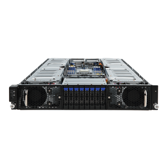
1
Front panel LED and buttons
2
System fan (GPU78_FAN)
3
2.5-inch hard disk drive #0
4
2.5-inch hard disk drive #1
5
2.5-inch hard disk drive #2
6
2.5-inch hard disk drive #3
2
4
1
1.
System Fan (GPU12E_FAN)
2.
VGA Port
3.
10/100/1000 Server Management LAN port
4.
Power Button with LED
5.
ID Button
6.
Reset Button
7.
System Status LED
8.
LAN Port #1 Active/Link LED
Hard Disk Drive
1
Front
2
3
PCI Express Card
1
Front
2
15
11
13
10
12
9
8
10
5
6
7
2
1
4
RDIMM Maximum Frequency Supported Table
DIMM
Frequency (MT/s)
DIMMs
2
1.2V
1R
2R
4DR
Populated
2DR
1
--
2667
1
2667
--
1
--
--
1
Not Supported
1
--
2667
1
2400
--
1
--
--
1
Not Supported
LRDIMM Maximum Frequency Supported Table
DIMM
Frequency (MT/s)
DIMMs
Populated
1.2V
1R
2S4R
4DR
--
--
Not Supported
1
2667
--
--
1
--
--
1
2667
1
--
--
Not Supported
1
2667
--
1
--
--
--
1
2667
System Front View
4 5 6 7 8 9 10
11
7
2.5-inch hard disk drive #4
8
2.5-inch hard disk drive #5
9
2.5-inch hard disk drive #6
10
2.5-inch hard disk drive #7
11
System fan (GPU34_FAN)
System Rear View
3 4 5 6 7
9.
10 GbE LAN Port x 2
10.
LAN Port #2 Active/Link LED
11.
USB 3.0 Port x 2
12.
System Fan (GPU56E_FAN)
13.
Power Supply (PSU1) Fan
14.
Power Supply Module Cord Socket
15.
NMI Button
16.
Power Supply (PSU2) Fan
17.
Power Supply Module Cord Socket
4
5
5
4
5
3
1
3
4
PN. xxxxxxxxxxxxxxxxxx
14
Advertisement


