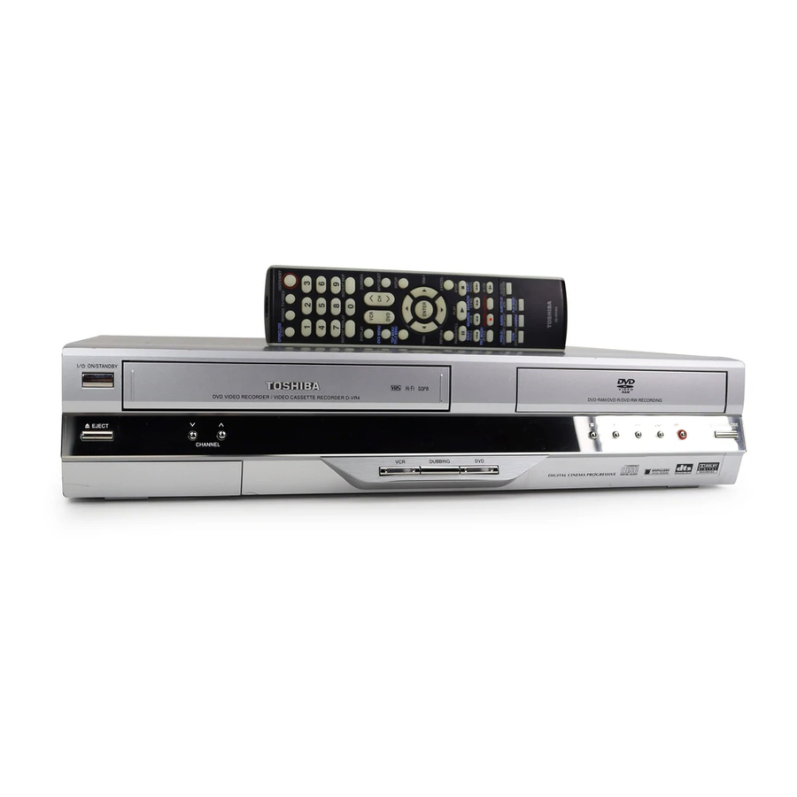
Toshiba D-VR4SU Service Manual
Hi-fi vcr & dvd video recorder
Hide thumbs
Also See for D-VR4SU:
- Owner's manual (88 pages) ,
- Service manual (9 pages) ,
- Owner's manual (92 pages)

Related Manuals for Toshiba D-VR4SU


Summary of Contents for Toshiba D-VR4SU
- Page 1 FILE NO. 810-200521 SERVICE MANUAL Hi-Fi VCR & DVD VIDEO RECORDER D-VR4SU D-VR4SC DOCUMENT CREATED IN JAPAN, March, 2005...
- Page 2 (90) days from the date you discover, or should have discovered, the defect. This limitation does not apply to implied warranties arising under state law. ©2005 Toshiba Corporation This device does not tape-record copy protected DVD Video Discs. Printed in Thailand Introduction...
-
Page 3: Table Of Contents
Introduction IMPORTANT SAFEGUARDS IMPORTANT SAFEGUARDS 13. LIGHTNING 19. REPLACEMENT PARTS When replacement parts are required, be sure the service technician uses replacement parts specified by To protect your unit from a lightning storm, or when it is left unattended and unused for long periods of time, the manufacturer or those that have the same characteristics as the original part. - Page 4 ROM drive, therefore, will not playback recorded vid- The usable format depends on the media type as shown • This recorder complies with current copyright • Toshiba is not liable for any damage or loss caused eos. in the below table.
- Page 5 Introduction Parts and functions Parts and functions Front Display window * This unit has a door on the front panel. Please open it to access the S-VIDEO jack and the AUDIO (L/R)/VIDEO IN (INPUT 2) jacks. Display window REW (Rewind) button CHANNEL buttons PLAY button...
- Page 6 Introduction Antenna connections Antenna connections If you are using an antenna system, follow these instructions. If you are a Cable TV subscriber, skip ahead DVD/VCR TO TV CONNECTION to page 18 for the proper connections. After you have connected the antenna to the DVD/VCR, you must connect the DVD/VCR to the TV. ANTENNA TO DVD/VCR CONNECTION Below are 3 common methods of connecting your DVD/VCR to a TV.
- Page 7 Introduction Connections with the TV or audio component Connections with the TV or audio component The exact arrangement you use to interconnect various video Connect to a stereo amplifier with audio output The unauthorized recording, use, distribution, and audio components to the DVD/VCR is dependent on the or revision of television programs, videotapes, You can enjoy high quality audio by connecting the audio output to your amplifier.
- Page 8 Various settings Setting the language Setting the parental control You can choose the language of the menu screen, Selectable languages: Some discs are specified as not suitable for chil- NOTES: • The selected level will apply to operations executed DVD menu, DVD audio and subtitles. dren.
- Page 9 Various settings Setting the disc / Other Setting the screen (SYSTEM SETUP) NOTES: NOTES: This section describes settings about the screen. Note for the field still and frame still: • During the finalization the cursor will move repeatedly. • During the cancelling finalization the cursor will move (with 480i interlaced scanning mode) Preparation: When the finalization finished, “DISC FINALIZED”...
- Page 10 Various settings Disc playback Playback procedure Setting the channel / Setting other items Preparation: This DVD/VCR is equipped with a channel memory You can set the switching interval between played • Turn ON the TV and set to the video input mode. feature that allows you to skip channels up or down back images in the slide show mode.
- Page 11 Disc playback Special playback Instant skip / Locating a specific scene Fast forward playback Instant skip Press SEARCH during normal playback. Use this function to skip commercials while you playback. Each press of SEARCH will increase the speed of the search NOTE: There may be a slight de- Press INSTANT SKIP during playback.
- Page 12 Disc playback Changing angles / Zooming / Karaoke playback Changing soundtrack language / Subtitles / To turn off the PBC Changing soundtrack language Changing angles You can select the language when you play a multilingual disc. When playing back a disc recorded with multi-angle facility, you can change the angle that you are viewing the scene from.
- Page 13 Please be advised that you must obtain permission from the applicable copyright owners to download copyrighted content, including music files, in any format, including the MP3 and WMA formats, prior to the downloading thereof. Toshiba has no right to grant and does not grant permission to download any coprighted content.
- Page 14 Tape playback Loading and unloading a cassette tape Cassette tape playback Preparation: • Turn ON the TV and set to the video input mode. Use only video cassette tapes marked • Press VCR to select the VCR mode. (The VCR indicator will light.) Load a prerecorded tape •...
- Page 15 Recording Read this before recording on disc Read this before recording on disc Types of disc Images that cannot be recorded The unauthorized recording, use, This section explains things you must You can use DVD-RAM, DVD-RW and DVD-R discs to record video. Some DVD-Video and broadcasts contain copy-restriction signals to distribution, or revision of television know to record onto a disc.
- Page 16 Recording Timer recording One-touch Timer Recording (OTR) Setting timer recording Preparation: Preparation: • Turn ON the TV and set to the video input mode. • Turn ON the TV and set to the video input mode. The timer recording system allows The One-touch Timer Recording •...
- Page 17 Recording Chase Playback Stereo recording and playback When a MTS STEREO broadcast is re- The VHS Hi-Fi audio system per- While recording a TV program on the DVD-RAM disc, press PLAY ceived, the word “STEREO” will appear on mits high fidelity recording of MTS to start chase playback.
- Page 18 Editing the disc Editing a playlist Editing a playlist Changing a title name Erasing a scene (Edit title) You can erase an unnecessary scene from the created playlist. Press TITLE MENU to display the title menu. When you erase the scene from the playlist, the scene is not erased from the original title.
- Page 19 Editing the disc Editing an original title Editing a playlist Erasing a playlist Preparation: • Turn ON the TV and set to the video input mode. You can erase the created playlist. Even if you erase the playlist, the • Load the recorded disc. original title will not be erased.
- Page 20 Editing the disc Editing an original title Editing an original title Erasing a scene (Edit title) Erasing an original title You can erase an unnecessary scene from the original title. You can erase an original title. Erasing the title deletes both the title Erase the scene after checking the title.
- Page 21 Editing the disc Dubbing Changing a disc name Dubbing a tape onto a disc Erasing a character Preparation: Press to select the type of letters in the You can erase the input character. • Turn ON the TV and set to the video input mode. list below and press ENTER.
- Page 22 Additional information Glossary Glossary A-B Repeat Playback parental control settings Video mode Playback that repeats between two set points, A and This is a digital sound system developed by Digital Level 1: Adult discs and general discs (R-rated This recording format is compatible with commercially Theater Systems for use in cinemas.
- Page 23 Dimensions: Width : 16-15/16 inches (430 mm) Toshiba America Consumer Products, L.L.C. ("TACP") makes the following limited warranties to original consumers in Height : 3-1/2 inches (89.5 mm) the United States. THESE LIMITED WARRANTIES EXTEND TO THE ORIGINAL CONSUMER PURCHASER OR Depth : 12-9/16 inches (318.5 mm)
- Page 24 • Place the unit on a workstation equipped to protect against static electricity, such as conductive mat. • Soldering iron with ground wire or ceramic type is used. • A worker needs to use a ground conductive wrist strap for body. A1-1 D-VR4SU/D-VR4SC...
- Page 25 (Reading should not be above 0.5mA) Leakage Current Tester 1.5K ohm 0.15 µF PRODUCT UNDER TEST TEST PROBE Test all exposed KNOWN EARTH 2-Blade polarized metal surfaces GROUND type cord set Fig. 1 AC Leakage Test A1-2 D-VR4SU/D-VR4SC...
- Page 26 Do not push objects through any openings in this unit, as they may touch dangerous voltage points or short out parts that could result in fire or electric shock. Never spill or spray any type of liquid into the unit. A1-3 D-VR4SU/D-VR4SC...
- Page 27 This reminder is provided to call the CATV system installer’s attention to Article 820-40 of the NEC that provides guidelines for proper grounding and, in particular, specifies that the cable ground shall be connected to the grounding system of the building, as close to the point of cable entry as practical. A1-4 D-VR4SU/D-VR4SC...
-
Page 28: Nec Section
EXAMPLE OF ANTENNA GROUNDING AS PER THE NATIONAL ELECTRICAL CODE ANTENNA LEAD IN WIRE GROUND CLAMP ANTENNA DISCHARGE UNIT (NEC SECTION 810-20) ELECTRIC SERVICE EQUIPMENT GROUNDING CONDUCTORS (NEC SECTION 810-21) GROUND CLAMPS POWER SERVICE GROUNDING NEC-NATIONAL ELECTRICAL CODE ELECTRODE SYSTEM (NEC ART 250, PART H) S2898A A1-5 D-VR4SU/D-VR4SC... - Page 29 Remove the Top Cabinet and Front Cabinet. (Refer to item 1 of the DISASSEMBLY INSTRUCTIONS.) Insert a fine rod (wire etc.) into the hole of the DECK CD as shown by the arrow. (Refer to Fig. 1) The Tray is opened. Manually open the Tray. DECK CD Fig. 1 A1-6 D-VR4SU/D-VR4SC...
- Page 30 Hold both keys for more than 2 second. The On Screen Display message 'FACTORY INITALIZE' will appear. The Tray Lock has now been cleared. Turn Unit OFF. NOTE: The above procedure will reset ALL of the player's settings to the default factory state. A1-7 D-VR4SU/D-VR4SC...
- Page 31 When soldering or unsoldering, completely remove all of the solder from the pins or solder area, and be sure to heat the soldering points with the lead free solder until it melts sufficiently. Recommendations Recommended lead free solder composition is Sn-3.0Ag-0.5Cu. D-VR4SU/D-VR4SC A1-8...
- Page 32 INTERCONNECTION DIAGRAM ....................H-31, H-32 WAVEFORMS ..........................I-1~I-5 MECHANICAL EXPLODED VIEW ..................... J1-1, J1-2 J2-1, J2-2 CHASSIS EXPLODED VIEWS ....................MECHANICAL REPLACEMENT PARTS LIST ................. K1-1~K1-4 CHASSIS REPLACEMENT PARTS LIST .................. K2-1, K2-2 K3-1~K3-40 ELECTRICAL REPLACEMENT PARTS LIST ................D-VR4SU/D-VR4SC A2-1...
- Page 33 120V, 60Hz Power Consumption 29 W at 120V 60Hz Stand by (FIP Off) 2.5 W at 120V 60Hz Stand by 3.5 W at 120V 60Hz Per Year -- W Protector Power Fuse Safety Circuit IC Protector (Micro Fuse) A3-1 D-VR4SU...
- Page 34 100 Hz - 4 kHz Hi-Fi Audio Signal Dynamic Range : More than 90dB Frequency Response 20Hz ~20kHz Wow And Flutter : Less than 0.01 %Wrms Channel Separation : More than 60 dB Harmonic Distortion : Less than 0.01 A3-2 D-VR4SU...
-
Page 35: Tv Screen
Virtual Surround (Spatializer(N-2-2)) External Audio Input Selection SAP On/Off Rec Setup Initial Rec Mode Initial Rec To Auto Chapter Index Picture Just Record Black Level (REC) CH Setup TV/CABLE Select Auto CH Memory Add / Delete Other JPEG Interval A3-3 D-VR4SU... - Page 36 Vocal On/Off Audio No. Audio L/R Yes (Video CD, SVCD) Zoom Marker No. Program Play Back Yes (CD, MP3, WMA,Video CD,SVCD) MP3 / WMA / JPEG Folder Name File Name File No Time Track No Progressive Scan Out On/Off A3-4 D-VR4SU...
- Page 37 (VCR Side) (VCR Side) Play (DVD Side) Pause / Still / Step (DVD Side) (DVD Side) RF Output CH Eject Stop FF / Cue REW / Review OTR (ITR) Hi-Fi CH/AV CABLE Progressive Scan Out PBC (Play Back Control) A3-5 D-VR4SU...
- Page 38 REC MODE / SPEED DUBBING AUDIO / AUDIO SELECT MARKER ZOOM / ZERO RETURN REPEAT A-B ANGLE / COUNTER RESET SUBTITLE / ATR PLAY MODE / REPEAT CLOCK / COUNTER CHAPTER MARK NAVI MARK TV / VIDEO PROGRESSIVE A3-6 D-VR4SU...
-
Page 39: Features
Yes(Disc Eject:Feb O/R Only) 、 Information Sheet (Return Disc Eject) AC Cord AV Cord Yes (1.2m) 75 Ohm Coaxial Cable Yes (0.9m) S-Video Cable 21pin cable 800 No Sticker Toll Free Insert Sheet Safety Tip Netflix Card PVC Warning Sheet A3-7 D-VR4SU... - Page 40 1 Corner / 3 Edges / 6 Surfaces Height (cm) 80 cm Container Stuffing 1,530 Sets/40' container G-21 Material Cabinet Front PS 94V2 or More / DECABROM Non-Halogen Demand Eyelet Demand G-22 Environment Environmental standard requirement (by buyer) Green procurement of TOSHIBA Pb-free Phase3 (Phase3A) A3-8 D-VR4SU...
- Page 41 GENERAL SPECIFICATIONS DVD-R/-RW/-RAM Video Recorder & Outline of the product VHS Player/Recorder DVD System Color System NTSC Disc Format DVD-R/-RW/-RAM DVD-R/-RW/-RAM, DVD-Video, CD-DA, Play CD-R/-RW, Video CD, SVCD Disc Diameter 120 mm Deck SW-9573 Rec Time (Approx.) 1 hour at 4.7GB Disc 2 hour 4 hour 6 hour...
- Page 42 GENERAL SPECIFICATIONS Power Power Source 120V, 60Hz Power Consumption 29 W at 120V 60Hz Stand by (FIP Off) 2.5 W at 120V 60Hz Stand by 3.5 W at 120V 60Hz Per Year -- W Protector Power Fuse Safety Circuit IC Protector (Micro Fuse) Regulation Safety UL/CSA...
-
Page 43: Reformat
GENERAL SPECIFICATIONS G-10 On Screen Menu Display Menu Type Character (DVD) Timer Rec Set Setup System Setup Language OSD Language DVD Menu Audio Subtitle Parental Password Lock/Unlock Rating Level Clock Clock Set Auto Clock Standard Time Daylight Saving Time Disc Setup New Disc Format Reformat as DVD VR Reformat as DVD Video... -
Page 44: Progressive Scan
GENERAL SPECIFICATIONS G-10 Title Menu (VR Mode) Chapter Add Chapter Mark Combine Chapters Play Rename Title Title Protect Thumb Nail Setting Delete Title Title Combine Title Divide Edit Title Rename Disc Genre Play List Play Chapter Rename Title Delete Title Title Combine Title Divide Edit Title... - Page 45 GENERAL SPECIFICATIONS On Screen Menu Display Menu Type Character Play/Stop/FF/ Rew/Rec/OT R (ITR)/T- (VCR) Rec/Pause/Ej ect/Tape In (Symbol Mark) CH/AV (LINE) Clock Repeat Tape Counter Index Tape Speed Decoder Sound ATR / Manual Tracking Hi-Fi Zero Return OTPB G-11 OSD Language DVD OSD English, French, Spanish VCR OSD...
- Page 46 GENERAL SPECIFICATIONS G-14 Remote Unit RC-KZ Control Glow in Dark Remocon Format TOSHIBA Remocon Format TOSHIBA Custom Code 45-BC Power Source Voltage (D.C) UM size x pcs UM-4 x 2 pcs Total Keys 51 Keys Keys POWER OPEN/CLOSE/EJECT 0 / 10...
-
Page 47: Picture Search
GENERAL SPECIFICATIONS G-15 Features Auto Power Off (DVD & VCR) CM Skip (30sec x 6 Times) Copy (Tape to Disc, Disc to Tape) Yes (By Conditioning) VIDEO PLUS+ (SHOWVIEW, G-CODE) Auto CH Memory Area Code Just Clock Auto Clock Set CABLE MTS (SAP) Energy Star... -
Page 48: Specifications
1 Corner / 3 Edges / 6 Surfaces Height (cm) 80 cm Container Stuffing 1,530 Sets/40' container G-21 Material Cabinet Front PS 94V2 or More / DECABROM Non-Halogen Demand Eyelet Demand G-22 Environment Environmental standard requirement (by buyer) Green procurement of TOSHIBA Pb-free Phase3 (Phase3A) A3-16 D-VR4SC... - Page 49 1-3: FLAP (Refer to Fig. 1-3) CP504 Open Flap to 90˚ and flex in direction of arrow (A), at the CP8302 CP8303 same time slide in direction of arrow (B). Fig. 1-4 CP8301 Then lift in direction of arrow (C). B1-1 D-VR4SU/D-VR4SC...
- Page 50 Move the Cassette Holder Ass’y to the back side. Remove the 3 screws 3. Disconnect the following connectors: (CP101, CP102, CP3001). Remove the AC Head Cover and VCR Deck in the direction of arrow. Bottom Plate Fig. 1-7 B1-2 D-VR4SU/D-VR4SC...
- Page 51 Move the Cassette Holder Ass'y to the front side. Push the Locker R to remove the Cassette Side R. Remove the Cassette Side L. Locker R Flap Lever Main Chassis Cassette Side R Link Lever Fig. 2-4 Link Unit Main Chassis Cassette Side L Fig. 2-2 B2-1 D-VR4SU/D-VR4SC...
- Page 52 Fig. 2-6-D. Loading Motor In case of the Tension Connect installation, install as the circled section of Fig. 2-6-E. Cassette Opener Tension Band Fig. 2-5-C Tension Connect Pink Fig. 2-6-C Loading Motor Capstan DD Unit White Fig. 2-5-D B2-2 D-VR4SU/D-VR4SC...
- Page 53 2-8: S REEL/T REEL/IDLER ARM ASS’Y/IDLER GEAR (Refer to Fig. 2-8-A) Idler Arm Ass’y Remove the S Reel and T Reel. Clutch Gear Remove the 2 Polyslider Washers 1. Fig. 2-8-C Remove the Idler Arm Ass’y and Idler Gear. B2-3 D-VR4SU/D-VR4SC...
- Page 54 Cylinder Unit Ass'y then tighten the screw (2), finally tighten the screw (3). A/C Head A/C Head Spring A/C Head Base • Screw Torque: 3 ± 0.5kgf•cm Fig. 2-12 • Screw Torque: 5 ± 0.5kgf•cm (Screw 1) Fig. 2-10-A B2-4 D-VR4SU/D-VR4SC...
- Page 55 Remove the Main Rod, Tension Lever, Loading Arm S Fig. 2-13-B Unit and Loading Arm T Unit. Main Loading Gear Silicon Bond Main Rod Main Chassis Loading Arm T Unit Tension Lever Capstan DD Unit Fig. 2-13-C Loading Arm S Unit Fig. 2-15-A B2-5 D-VR4SU/D-VR4SC...
- Page 56 1. In case of the Clutch Ass’y installation, install it with inserting the spring of the Clutch Ass’y into the dent of the Coupling Gear. (Refer to Fig. 2-16-B) [OK] Cassette Guide Post Clutch Ass’y [NG] Cassette Guide Post Coupling Gear Fig. 2-17-C Fig. 2-16-B B2-6 D-VR4SU/D-VR4SC...
- Page 57 Shield Wire. (Refer to Fig. 3-4.) NOTE Do not move the Braided Shield Wire in the vertical Blower type IC direction towards the IC pattern. desoldering machine Braided Shield Wire Soldering Iron Fig. 3-2 IC pattern Fig. 3-4 B3-1 D-VR4SU/D-VR4SC...
- Page 58 Fig. 3-6 3. Absorb the solder left on the lead using the Braided Shield Wire. (Refer to Fig. 3-7.) NOTE Do not absorb the solder to excess. Soldering Iron Braided Shield Wire Fig. 3-7 B3-2 D-VR4SU/D-VR4SC...
- Page 59 Fast Forward, Flipflop SENS Sensor Frequency Generator Search Mode FL SW Front Loading Switch Serial Input Frequency Modulation Sound Intermediate Frequency Frequency Sub Carrier Serial Output Forward Solenoid Generator Standard Play Ground Serial Strobe H.P.F High Pass Filter Switch C1-1 D-VR4SU/D-VR4SC...
- Page 60 UNREG Unregulated Volt Voltage Controlled Oscillator Video Intermediate Frequency Vertical Pulse, Voltage Display V.PB Video Playback Variable Resistor V.REC Video Recording Visual Search Fast Forward Visual Search Rewind Voltage Super Source V-SYNC Vertical-Synchronization Voltage Tuning X’TAL Crystal Luminance/Chrominance C1-2 D-VR4SU/D-VR4SC...
- Page 61 DVD mode STOP 2 sec. NOTE: The function will only work without the setting of DVD disc (No disc) at DVD mode. DVD mode Region setting. STOP 2 sec. (STOP) Refer to the “WHEN REPLACING NEW DVD LOADER”. C2-1 D-VR4SU/D-VR4SC...
- Page 62 Romcorrection data check sum. PLAY/REC 0000 PLAY/REC total hours. = (16 x 16 x 16 x thousands digit value) Fig. 1 + (16 x 16 x hundreds digit value) + (16 x tens digit value) + (ones digit value) C3-1 D-VR4SU/D-VR4SC...
- Page 63 Clean the full erase head in the same manner. (Refer to the figure below.) Do not exert force against the cylinder head. Do not move the chamois upward or downward on the head. Use the chamois one by one. Cylinder Head Audio Control Head C3-2 D-VR4SU/D-VR4SC...
- Page 64 Press both CH UP button on the set and the PLAY button on the set for more than 2 seconds. After the finishing of the initializing of shipping, the unit will turn off automatically. The unit will now have the correct DATA for the new MEMORY IC. C4-1 D-VR4SU/D-VR4SC...
- Page 65 Press both CH UP button on the set and the PLAY button on the set for more than 2 seconds. After the finishing of the initializing of shipping, the unit will turn off automatically. The unit will now have the correct DATA for the new MEMORY IC. C4-2 D-VR4SU/D-VR4SC...
- Page 66 Information screen will be displayed on the TV Monitor. (Refer to Fig. 1) If the writing Region No. is appeared, the Region setting is completed. Turn off the power. Vaddis Timer Ver. RXM53021 OEC0154A108B C.Sum 06010040 121B Accum 000000 0000 MATUSHITADVD-RAM SW-9573 MR19 Region No. Region-1 Fig. 1 C4-3 D-VR4SU/D-VR4SC...
- Page 67 Information screen will be displayed on the TV Monitor. (Refer to Fig. 1) When the changed version displays, the Re-write will be completed. Turn off the power Firmware Version Vaddis Timer Ver. RXM53021 OEC0154A108B C.Sum 06010040 121B Accum 000000 0000 MATUSHITADVD-RAM SW-9573 MR19 Region-1 Fig. 1 C5-1 D-VR4SU/D-VR4SC...
- Page 68 In case of using a cassette tape, press the EJECT button to insert or eject a cassette tape. Turn on the power and re-check the cable before checking the trouble points. When you servicing with connection of DVD, perform the operations above step 2 to step 3. D1-1 D-VR4SU/D-VR4SC...
- Page 69 50~90gf•cm during playback in SP mode. 10(+0.2, -0)mm Confirm that the left meter of the torque tape indicates 25~40gf•cm during playback in SP mode. Tentelometer (JG185) Height Adjustment Washer 2.6x4.7xT0.13 Video Tape 2.6X4.7xT0.25 Fig. 1-1-B Guide Roller P1 Post Fig. 1-3 D2-1 D-VR4SU/D-VR4SC...
- Page 70 Cassette Holder Ass'y Envelope Fig. 1-4-A (TP101) Torque Gauge/Adapter CH-1 CH-2 (JG002F/JG002B) Track Track CH-2 SW Pulse (TP3001) Torque Gauge/Adapter (JG002E/JG002B) Fig. 2-1-A Entrance Exit S Reel Fig. 1-4-B T Reel A : B ≥ 3 : 2 Fig. 2-1-B D2-2 D-VR4SU/D-VR4SC...
- Page 71 Audio/Control Head picture and sound again. Reflected picture of Stamp Mark P4 Cap Stamp Mark Fig. 2-2-A Audio/Control Head [OK] [NG] Fig. 2-2-B Audio/Control Head Tape 0.25±0.05mm Fig. 2-2-C D2-3 D-VR4SU/D-VR4SC...
- Page 72 3. MECHANISM ADJUSTMENT PARTS LOCATION GUIDE 1. Tension Connect P4 Post 2. Tension Arm T Brake Spring 3. Guide Roller T Reel 4. Audio/Control Head S Reel 5. X value adjustment driver hole Adjusting section for the Tension Arm position D2-4 D-VR4SU/D-VR4SC...
- Page 73 2 seconds to set tracking to center. Press both CH UP button on the set and the STOP button on the set for more than 2 seconds. CH-2 6.5H CH-1 Fig. 1-1-A CH-2 CH-1 6.5H Fig. 1-1-B D3-1 D-VR4SU/D-VR4SC...
- Page 74 CD7304 CP102 CP506 CD504 CP103 CD7301 FE HEAD CD4003 CD7302 CD103 AC HEAD TP101 CD7303 TP3001 CP4006 CP7301 CP651 CP7304 J655 CD653 OPERATION1 PCB DVD/HD MPEG PCB J603 DISPLAY PCB OS601 V601 CP602 CP604 OPERATION2 PCB DECK CD D3-2 D-VR4SU/D-VR4SC...
- Page 75 Check of T501 Does display light ? linked to L506 ? and peripheral circuit. Check of V601 and peripheral circuit. Is the voltage at Check IC3001. pin 30 of IC 3001 0V ? Check of T501 and peripheral circuit. D-VR4SU/D-VR4SC...
- Page 76 Inserting a cassette and push play button. Does the power cut Check CAPSTAN DD UNIT after 3 seconds? and CYLINDER UNIT. Does the power cut Check Q3001, Q3002 after about 6 seconds ? and CAPSTAN BELT. Check the POWER BLOCK. D-VR4SU/D-VR4SC...
- Page 77 TROUBLESHOOTING GUIDE AT PLAYBACK AND RECORDING, CYLINDER MOTOR UNLOAD Is the voltage at pin 8 of Check IC502. CP3001 about DC12.6V ? In playback, is at pin 12 of Check IC3001. CP3001 about DC2.6V ? Check the DECK BLOCK. D-VR4SU/D-VR4SC...
- Page 78 Is AUDIO HEAD Change AUDIO HEAD. scratched ? At playback, is input about Change CAPSTAN DD UNIT. 4.5Vp-p of a rectangular wave at pin 9 of IC3001? At playback, is pin 5 of Check IC3001. CP3001 3.5V ? Check AUDIO BLOCK. D-VR4SU/D-VR4SC...
- Page 79 When a CASSETTE can Check LED of DECK, not inserted, is pin 25 of PHOTO SENSOR. IC3001 5V ? When a CASSETTE is Change inserted, is pin 8 of LOADING MOTOR. CP3001 12.6V ? Check circuit of POWER BLOCK. D-VR4SU/D-VR4SC...
- Page 80 Defective CASSETTE Does another CASSETTE or cassette loading block. insert ? Does SW3001 and Correctly SW3001 REC LEVER and REC LEVER set. correctly set ? After inserting CASSETTE, is pin 51 Check SW3001. of IC3001 0V ? Check IC3001. D-VR4SU/D-VR4SC...
- Page 81 TROUBLESHOOTING GUIDE CAN NOT FF/REW At FF/REW, does voltage Check of IC3001. at pin 98 of IC3001 change ? Check DECK MECHANISM. D-VR4SU/D-VR4SC...
- Page 82 At play, is the voltage at pin 12 of CP3001 2.6V ? Change CYLINDER unit. Is PG PULSE signal Is there HEAD SW inputted to pin 104 PULSE at TP3001? of IC3001 ? Change IC3001. Check Q3002 and Q3003. D-VR4SU/D-VR4SC...
- Page 83 TROUBLESHOOTING GUIDE AT PLAY, THE PICTURE JITTERS VERTICAL MINUTELY Is FG wave of CP3001 Change at pin 11 5V ? CYLINDER MOTOR. Change IC3001. Is pin 12 of CP3001 2.6V ? Change CYLINDER MOTOR. D-VR4SU/D-VR4SC...
- Page 84 DOES NOT OPERATE Does the CTL pulse signal (about 2.5Vp-p) In auto tracking, is the Check CONTROL HEAD. appear at pin 7 of IC3001?. voltage at pin 24 of IC3001 2.5Vp-p more than DC 0.2V ? Change IC3001. E-10 D-VR4SU/D-VR4SC...
- Page 85 MODE IS ACTIVE, UNIT STOPS IMMEDIATELY Refer to section "CAPSTAN Does CAPSTAN DD DD MOTOR NOT MOTOR rotate ? ROTAING". Is there REEL SENSOR PULSE signal at pin 69 and 70 Check Q3005 and Q3006. of IC3001? Change IC3001. E-11 D-VR4SU/D-VR4SC...
- Page 86 ? The height of GUIDE POST Is a height of GUIDE POST readjust. maximum ? Is PG SHIFTER Adjust PG SHIFTER. adjustment 6.5H ? Change IC101 Is a wave of PB-Y unusual ? and peripheral circuit. Change IC101. E-12 D-VR4SU/D-VR4SC...
- Page 87 "AT E-E, NO PICTURE" appear ? Is there video signal Change IC101. at pin 26 of IC101? Is there video signal Change IC8302. at pin 7 of IC8302? Is there video signal Change IC3001. at pin 19 of IC3001? Check J8005. E-13 D-VR4SU/D-VR4SC...
- Page 88 26 of IC101? Is there video signal Change IC8308. at pin 7 of IC8308? Check J8001. Is there video signal of Change IC3001. at pin 19 IC3001? Check at pin 5 of J8005 and peripheral circuit. E-14 D-VR4SU/D-VR4SC...
- Page 89 Is there color signal in Change IC8308. video signal at pin 7 of IC8308 ? Is there color signal in Change IC3001. video signal at pin19 of IC3001 ? Check at pin 5 of J8005 and peripheral circuit. E-15 D-VR4SU/D-VR4SC...
- Page 90 Is noisy a wave of video Change IC8308. signal at pin 7 of IC8308 ? Is noisy a wave of video Change IC3001. signal at pin 19 of IC3001 ? Check J8005 at pin 5 and peripheral circuit. E-16 D-VR4SU/D-VR4SC...
- Page 91 Is there CHROMA signal at Check TU301, J8002, J603, pin 30 and 32 of IC101? IC8309 and circuit around it. Is there CHROMA signal at Change IC101. pin 26 of IC101? Refer to "AT PLAYBACK, THE COLOR DOES NOT APPEAR". E-17 D-VR4SU/D-VR4SC...
- Page 92 Change IC101 and check Is there audio signal at pin peripheral circuit of pin 10 10 of IC101 ? of IC101. Check whether there are not a damage, dirt in AUDIO HEAD and peripheral circuit of pin 4 of IC701. E-18 D-VR4SU/D-VR4SC...
- Page 93 In playback, is there voltage Check POWER BLOCK. at pin 2 of CP3001 12V ? In playback, is there voltage Change IC3001. at pin 102 of IC3001 2.5V ? DD MOTOR rotate now ? If not, replace it. E-19 D-VR4SU/D-VR4SC...
- Page 94 TUNER pin 76, 78 and 80 of or audio input jack to IC701 . IC101 ? Is there a sine wave Change L101. at pin 5 of L101 ? Check lead wire of A/C HEAD and CONNECTOR. E-20 D-VR4SU/D-VR4SC...
- Page 95 TROUBLESHOOTING GUIDE THE CASSETTE INSERT, BUT THE TAPE DOES NOT MOVE Check LOADING MOTOR Does the mode and MODE SENSOR appear at display ? RELATION DEPARTMENT. Does operate with Check IC3001. remote control ? Check operation PCB. E-21 D-VR4SU/D-VR4SC...
- Page 96 Is the voltage at pin 96 Is the BASE of Change IC3001. of IC3001 5V ? Q103 5V ? Is there video signal Change IC101. at pin 26 of IC101 ? Check CYLINDER UNIT and circuit around of CP101. E-22 D-VR4SU/D-VR4SC...
- Page 97 Check J8005 and peripheral Is there audio signal at circuit. pin 78 and 80 of IC701 ? Is there audio signal at Check J8002, J601, J602 pin 7, 9, 69 and 71 and peripheral circuit. of IC701? Change IC701. E-23 D-VR4SU/D-VR4SC...
- Page 98 Change IC3001. of IC3001 5V ? Is there audio signal at Check J8002 and J602. pin 6 and 9 of IC701 ? Is there audio signal at Change IC701. pin 6 of IC701 ? Check circuit around of J8005. E-24 D-VR4SU/D-VR4SC...
- Page 99 3 and 54 of IC701 9V ? Is there Audio signal at pin Check J8002, J602 and J603. 7, 9, 69 and 71 of IC701 ? Is there Audio signal at Change IC701. pin 8 and 80 of IC701? Check circuit around of J8005. E-25 D-VR4SU/D-VR4SC...
- Page 100 13 of TU301. 57 of IC701 ? Is there audio signal at Change IC701. pin 78 and 80 of IC701 ? Is there audio signal a emitter of Check IC701. Q8017 and Q8018 ? Check circuit around of J8005. E-26 D-VR4SU/D-VR4SC...
- Page 101 Check circuit around of TU301. pin 57 of IC701 ? Is there audio signal at pin Change IC701. 78 and 80 of IC701 ? Is there audio signal Check IC701. a collector of Q8017 and Q8018 ? Check circuit around of J8005. E-27 D-VR4SU/D-VR4SC...
- Page 102 Check circuit of HEAD AMP Is there audio signal at and CYLINDER UNIT. pin 24 and 27 of IC701 ? Is there audio signal at Change IC701. pin 78 and 80 of IC701 ? Check circuit around of J8005. E-28 D-VR4SU/D-VR4SC...
- Page 103 9, 57, 69 and71 of IC701 ? Is there audio signal at pin Change IC701. 78 and 80 of IC701 ? At recording and play, is Check CYLINDER UNIT. there signal at pin 7, 8 and 9 of CP101 0? Check IC701. E-29 D-VR4SU/D-VR4SC...
- Page 104 Check P.CON 12V and CP504 about DC12V ? P.CON+D5V line of and pin 4 of CP504 about POWER BLOCK. DC5V ? Is the lose connection Check CD504 connection at CD504 to CP504 and to CP504 and DECK. DECK ? Check DECK. E-30 D-VR4SU/D-VR4SC...
- Page 105 2, 4, 9 and 207 of peripheral circuit. IC4009 ? Is there a signal in at pin Check IC4001 and 97, 107, 108, 117, 118 and 127 of IC4001 with each peripheral circuit. output mode ? Check VCR block. E-31 D-VR4SU/D-VR4SC...
- Page 106 Is there a signal in at Check IC4001 and peripheral pin 1, 2 and 3 of IC7301 ? circuit. Check IC7301 and peripheral Is there a signal in at circuit. pin 7 and 8 of IC7301 ? Go to NO AUDIO ON PLAYBACK. E-32 D-VR4SU/D-VR4SC...
- Page 107 Is there a signal in at Check IC4001 and peripheral pin 1, 2 and 3 of IC7301 ? circuit. Check IC7301 and peripheral Is there a signal in at circuit. pin 7 and 8 of IC7301 ? Go to NO AUDIO ON PLAYBACK. E-33 D-VR4SU/D-VR4SC...
- Page 108 117 of IC4001 ? Check IC8302 and peripheral Is the waveform at pin circuit. 7 of IC8302 ? Check IC3001 and peripheral Is the waveform at pin circuit. 19 of IC3001 ? Check J8005 and peripheral circuit. E-34 D-VR4SU/D-VR4SC...
- Page 109 118 of IC4001 ? Check CP7302 connection Is there Y signal at pin to CP8301. 12 of CP8301 ? Check IC8304 and Is there Y signal at pin peripheral circuit. 2 of IC8304 ? Check J8003 and peripheral circuit. E-35 D-VR4SU/D-VR4SC...
- Page 110 127 of IC4001 ? Check CP7302 connection Is there C signal at to CP8301. pin 8 of CP8301 ? Check IC8305 and Is there C signal at pin peripheral circuit. 2 of IC8305 ? Check J8003 and peripheral circuit. E-36 D-VR4SU/D-VR4SC...
- Page 111 NO PLAYBACK PICTURE OF YUV JACK Check IC4001 and Is there Y signal at peripheral circuit. pin 108 of IC4001 ? Check CP7302 connection Is there Y signal at pin to CP8301. 14 of CP8301 ? Check J8006 and peripheral circuit. E-37 D-VR4SU/D-VR4SC...
- Page 112 Is there U &V signals at circuit. pin 97 and 107 of IC4001 ? Is there U & V signals Check CP7302 connection at pin 16 and 18 of to CP8301. CP8301 ? Check J8006 and peripheral circuit. E-38 D-VR4SU/D-VR4SC...
- Page 113 Check IC8306 and peripheral Is there waveform at pin circuit. 1 and 7 of IC8306 ? Is there waveform at pin Check IC701 and peripheral circuit. 78 and 80 of IC701 ? Check J8005 and peripheral circuit. E-39 D-VR4SU/D-VR4SC...
- Page 114 79, 98, 128 and 142 of and peripheral circuit. IC4001 ? Is there a signal in at Check IC4001, DVD DECK pin 97, 107, 108, 117, and peripheral circuit. 118 and 127 of IC4001 ? Check VCR block. E-40 D-VR4SU/D-VR4SC...
- Page 115 Is there a signal in at pin 1, and peripheral circuit. 2 and 3 of IC7301 ? Check IC7301 and peripheral Is there a signal in at pin circuit. 7 and 8 of IC7301 ? Check VCR block. E-41 D-VR4SU/D-VR4SC...
- Page 116 (OPERATION 1 PCB ASS'Y) 101E 101S 101J 101O 101I 101K 101W 101G 101X 101F 101M 101Q 101V 101D 101L 101L 101T 101H 101G 101P 101N 101M 101R 101K 101U 101C 101A 101B PCB280 101U (OPERATION 2 PCB ASS'Y) J1-1 D-VR4SU/D-VR4SC...
- Page 117 MECHANICAL EXPLODED VIEW (PACKING DIAGRAM) 130, 131, 132, 133, 134, 135, 136, 137, 142 CD6002, CD6003 TM601 J1-2 D-VR4SU/D-VR4SC...
- Page 118 CHASSIS EXPLODED VIEW (TOP VIEW) CD1501 M2003 UN4001 H5002 H5001 CD1502 M101 NOTE: Applying positions AA for the grease are displayed for this section. CLASS MARK Check if the correct grease is applied for each position. GREASE J2-1 D-VR4SU/D-VR4SC...
- Page 119 CHASSIS EXPLODED VIEW (BOTTOM VIEW) M2001 CD1501 CD1502 NOTE: Applying positions AA for the grease are displayed for this section. CLASS MARK Check if the correct grease is applied for each position. GREASE J2-2 D-VR4SU/D-VR4SC...
- Page 120 INFORMATION SHEET AE004980 J2D60143A NETFLIX CARD AE005534 J2E50628A WARNING SHEET AE006671 J2G10101A INSTRUCTION BOOK AE006672 J2G10107A QUICK SET-UP SHEET AE007249 J2G10199B INFORMATION SHEET AE001853 8965TS1017 CUSHION 65TS10-10 17.5x20x14 AE007250 800WFA0056 CUSHION 25x50xT4 AE007251 795WCAA322 PAD(M2G1) AE007252 7250000598 SHEET,PC K1-1 D-VR4SU...
- Page 121 AE004724 8109K3060U SCREW,TAP TITE(B) BIND(3D) AE003524 8109I30A0U SCREW,TAP TITE(B) WH7 3x10 AE005538 8110326A0U SCREW,TAP TITE(P) FLAT 2.6x10 AE003532 810723040U SCREW,TAP TITE(S) BIND AE006674 810223060U SCREW,BIND AE003530 811022680U SCREW,TAP TITE(P) BIND 2.6x8 AE007202 810923053U SCREW,TAP TITE(B) R BIND 3x5.3 K1-2 D-VR4SU...
- Page 122 MECHANICAL REPLACEMENT PARTS LIST Location No. TSB P/N Reference No. Description AE006631 7A7010087A FRONT CABI ASS'Y 101A AE006632 701WPJ1326 CABINET,FRONT 101B AE006633 711WAD0001 PLATE 101C AE006634 711WPB0012 DOOR 101D AE006635 711WPD0672 PLATE,DISPLAY 101E AE006636 712WPJ0905 FLAP,VCR 101F AE006637 712WPJ0906 FLAP,DVD 101G AE006638 713WPA0358...
- Page 123 MECHANICAL REPLACEMENT PARTS LIST Location No. TSB P/N Reference No. Description AE006673 8109130B7U SCREW,TAP TITE(B) R PAN 3x27 AE005474 810923070U SCREW,TAP TITE(B) R BIND AE003526 810923080U SCREW,TAP TITE(B) BIND AE004724 8109K3060U SCREW,TAP TITE(B) BIND(3D) AE003524 8109I30A0U SCREW,TAP TITE(B) WH7 3x10 AE005538 8110326A0U SCREW,TAP TITE(P) FLAT...
- Page 124 H5001 AE004714 1523Q91004 HEAD,AUDIO CONTROL VTR-1X2RPE22-772 H5002 AD301676 1543Q02014 HEAD (FULL ERASE) VTR-1X2ERS11-154 M101 AE005552 1596S98002 MOTOR,LOADING MDB2B66B M2001 AE005853 1510S98044 CAPSTAN DD UNIT F2QVB73B M2003 AE003673 1589S11020 MICRO MOTOR I2OAL34 UN4001 AE006680 A2F401H500 CYLINDER UNIT ASS'Y A2F401H500 K2-1 D-VR4SU...
- Page 125 CHASSIS REPLACEMENT PARTS LIST Location No. TSB P/N Reference No. Description AE006965 A2G001H420A DECK ASSY A2G001H420A AE005514 85OA400245 PINCH ROLLER BLOCK VA2 AE006679 85OP900759 LEVER,FLAP(S) BZ710193 85OP200290 BELT,CAPSTAN (S) BZ710515 85OP600581 WORM AE005919 85OP500091 BASE,AC HEAD BZ710112 85OP800324 SPRING,AC HEAD AE006676 85OA000529 MAIN CHASSIS ASS'Y(S)
- Page 126 390 OHM 1/4W R522 BZ210233 R4X5T6272F R,METAL 2.7K OHM 1/6W R523 BZ210119 R002T4102J OHM 1/4W R524 79091119 R002T4331J 330 OHM 1/4W R525 BZ210182 R002T4103J 10K OHM 1/4W R526 AE000360 R002T4561J 560 OHM 1/4W R527 BZ210192 R002T4223J 22K OHM 1/4W K3-1 D-VR4SU...
- Page 127 1.5K OHM 1/16W R724 BZ210119 R002T4102J OHM 1/4W R725 AE001781 R803R9101J 100 OHM 1/16W R726 AE001781 R803R9101J 100 OHM 1/16W R727 AE001790 R803R9222J 2.2K OHM 1/16W R728 AE001796 R803R9471J 470 OHM 1/16W R729 79091400 R803R9393J 39K OHM 1/16W K3-2 D-VR4SU...
- Page 128 47K OHM 1/16W R3032 BZ210166 R002T4562J 5.6K OHM 1/4W R3033 AE001896 R803R9474J 470K OHM 1/16W R3034 AE001797 R803R9473J 47K OHM 1/16W R3037 AE002148 R803R9183J 18K OHM 1/16W R3038 AE001784 R803R9103J 10K OHM 1/16W R3039 AE001891 R803R9223J 22K OHM 1/16W K3-3 D-VR4SU...
- Page 129 OHM 1/16W R4058 AD302345 R803R9472J 4.7K OHM 1/16W R4059 79091142 R803R9220J OHM 1/16W R4060 AE006623 R803R9510J OHM 1/16W R4061 AE006623 R803R9510J OHM 1/16W R4062 AE006623 R803R9510J OHM 1/16W R4063 AE006623 R803R9510J OHM 1/16W R4064 AE001799 R803R9562J 5.6K OHM 1/16W K3-4 D-VR4SU...
- Page 130 4.7K OHM 1/16W R4139 AE001886 R803R9100J OHM 1/16W R4140 AE001886 R803R9100J OHM 1/16W R5719 AE001784 R803R9103J 10K OHM 1/16W R7302 AE001899 R803R9750F OHM 1/16W R7303 AE001899 R803R9750F OHM 1/16W R7304 AE001899 R803R9750F OHM 1/16W R7305 AD302345 R803R9472J 4.7K OHM 1/16W K3-5 D-VR4SU...
- Page 131 R8041 AE001007 R002T4123J 12K OHM 1/4W R8042 BZ210192 R002T4223J 22K OHM 1/4W R8043 BZ210107 R002T4750J OHM 1/4W R8044 BZ210107 R002T4750J OHM 1/4W R8045 AE001797 R803R9473J 47K OHM 1/16W R8301 AE001899 R803R9750F OHM 1/16W R8302 AE001803 R803R9750J OHM 1/16W K3-6 D-VR4SU...
- Page 132 0.1 UF 50V F C127 AE001731 CS0PCH4G2J 180 PF 50V CH C130 AE001275 CS0PF0415Z 0.1 UF 50V F C131 AE000336 E02LU1101M 100 UF 10V C132 BZ110074 E50HU5010M UF 50V C133 AE000838 CS0PB0N16K UF 10V B C134 AE000838 CS0PB0N16K UF 10V B K3-7 D-VR4SU...
- Page 133 BZ110190 E02LU2221M 220 UF 16V C533 BZ110117 CQGTB04Q3K 0.0047UF 50V B C534 BZ110061 C0JTB0513K 0.001 UF 500V B C536 AE001768 E50HU0221M 220 UF 6.3V C538 AD300789 CQGTF0415Z 0.1 UF 50V F C540 79091044 C0JTB05H2K 220 PF 500V B K3-8 D-VR4SU...
- Page 134 C749 AE001734 CS0PCH4U2J 680 PF 50V CH C750 AE001544 E50HU3100M UF 25 V C751 BZ110263 E50HU2220M UF 16 V C752 AE001275 CS0PF0415Z 0.1 UF 50V F C753 AE001770 E50HU54R7M 4.7 UF 50V C754 BZ110150 E50HU0101M 100 UF 6.3V K3-9 D-VR4SU...
- Page 135 CS0PCH4W2J 820 PF 50V CH C3024 79091061 CS0PCH4G1J PF 50V CH C3025 79091061 CS0PCH4G1J PF 50V CH C3026 AE001725 CS0PB0413K 0.001 UF 50V B C3027 AE001730 CS0PCH4E2J 150 PF 50V CH C3028 AE002124 CS0PB0315K 0.1 UF 25V B K3-10 D-VR4SU...
- Page 136 0.1 UF 50V F C4039 AE001275 CS0PF0415Z 0.1 UF 50V F C4040 AE001275 CS0PF0415Z 0.1 UF 50V F C4041 AE001726 CS0PB0414K 0.01 UF 50V B C4042 AE001726 CS0PB0414K 0.01 UF 50V B C4043 AE001726 CS0PB0414K 0.01 UF 50V B K3-11 D-VR4SU...
- Page 137 0.001 UF 50V B C4110 AE001275 CS0PF0415Z 0.1 UF 50V F C4113 AE001275 CS0PF0415Z 0.1 UF 50V F C4114 AE001275 CS0PF0415Z 0.1 UF 50V F C4115 AE001732 CS0PCH4H1J PF 50V CH C4116 AE001275 CS0PF0415Z 0.1 UF 50V F K3-12 D-VR4SU...
- Page 138 UF 16V C7325 AE001275 CS0PF0415Z 0.1 UF 50V F C7328 AE005073 E61UM2100D UF 16V C7329 AE005073 E61UM2100D UF 16V C7330 AE001725 CS0PB0413K 0.001 UF 50V B C7331 AE002124 CS0PB0315K 0.1 UF 25V B C7332 AE000838 CS0PB0N16K UF 10V B K3-13 D-VR4SU...
- Page 139 C8310 AE001544 E50HU3100M UF 25 V C8311 AE001731 CS0PCH4G2J 180 PF 50V CH C8312 AE001726 CS0PB0414K 0.01 UF 50V B C8313 BZ210177 E02LU2470M UF 16V C8314 AE001726 CS0PB0414K 0.01 UF 50V B C8315 AE002130 CS0PCH4Q1J PF 50V CH K3-14 D-VR4SU...
- Page 140 BZ410113 D97U02201B DIODE,ZENER MTZJ22B T-77 ! D512 AE002498 D2LKB340F0 DIODE,SCHOTTKY SB340FL-6737 D514 BZ410006 D1VT001330 DIODE,SILICON 1SS133T-77 ! D515 AE005172 D27A85T400 DIODE,SCHOTTKY RB085T-40 D516 BZ410006 D1VT001330 DIODE,SILICON 1SS133T-77 D517 BZ410006 D1VT001330 DIODE,SILICON 1SS133T-77 ! D518 BZ410006 D1VT001330 DIODE,SILICON 1SS133T-77 K3-15 D-VR4SU...
- Page 141 MM1506XNRE IC8306 AE006607 I0QF020680 NJM2068M(TE1) IC8307 BZ611139 I0QF02534V NJM2534V(TE2) IC8308 BZ611139 I0QF02534V NJM2534V(TE2) IC8309 BZ611139 I0QF02534V NJM2534V(TE2) IC8310 BZ611139 I0QF02534V NJM2534V(TE2) TRANSISTORS Q101 BZ510109 TCAA3875SY TRANSISTOR,SILICON KTC3875S_Y_RTK Q102 BZ510109 TCAA3875SY TRANSISTOR,SILICON KTC3875S_Y_RTK Q103 BZ510026 TPYJC05001 COMPOUND TRANSISTOR DTA124EKAT146 K3-16 D-VR4SU...
- Page 142 COMPOUND TRANSISTOR DTA124EKAT146 Q8027 BZ510107 TPAAA05001 COMPOUND TRANSISTOR KRA101SRTK Q8028 BZ510021 TNYJC05001 COMPOUND TRANSISTOR DTC124EKAT146 Q8029 BZ510026 TPYJC05001 COMPOUND TRANSISTOR DTA124EKAT146 Q8030 BZ510026 TPYJC05001 COMPOUND TRANSISTOR DTA124EKAT146 Q8031 BZ510026 TPYJC05001 COMPOUND TRANSISTOR DTA124EKAT146 Q8032 BZ510109 TCAA3875SY TRANSISTOR,SILICON KTC3875S_Y_RTK K3-17 D-VR4SU...
- Page 143 AE004761 063D700010 JACK MDC-012V1-A_LF J8001 AE004334 063D700009 JACK MDC-070V-A_LF J8002 AE002759 060J431020 RCA JACK MSP-213V2-432_NI_LF J8003 AE002813 063D700008 JACK MDC-070V-B_LF J8004 AE002760 060J411033 RCA JACK MSP-213V1-732_NI_LF J8005 AE002758 060J411031 RCA JACK MSP-213V1-432_NI_LF J8006 AE002761 060J411032 RCA JACK MSP-213V1-652_NI_LF K3-18 D-VR4SU...
- Page 144 CP602 AD301649 067U002019 WIRE HOLDER B2013H02-2P CP603 AE006575 069EV73050 CONNECTOR PCB SIDE 00_6232_007_102_800+ CP604 AD301649 067U002019 WIRE HOLDER B2013H02-2P CP651 AE006936 069EVB3030 CONNECTOR PCB SIDE 00_6232_011_006_800+ CP652 AE006574 069EV73030 CONNECTOR PCB SIDE 00_6232_007_006_800+ CD4003 AE006585 06CUJB1401 CORD,CONNECTOR CUJB1401 K3-19 D-VR4SU...
- Page 145 X4001 AE006589 100DT02712 CRYSTAL DSO751SV RESISTOR RC....CARBON RESISTOR CAPACITORS CC....CERAMIC CAPACITOR CE....ALUMI ELECTROLYTIC CAPACITOR CP....POLYESTER CAPACITOR CPP....POLYPROPYLENE CAPACITOR CPL....PLASTIC CAPACITOR CMP....... METAL POLYESTER CAPACITOR CMPL....METAL PLASTIC CAPACITOR CMPP....METAL POLYPROPYLENE CAPACITOR K3-20 D-VR4SU...
- Page 146 ELECTRICAL REPLACEMENT PARTS LIST Location No. TSB P/N Reference No. Description RESISTORS R101 AE000360 R002T4561J 560 OHM 1/4W R102 AD302345 R803R9472J 4.7K OHM 1/16W R103 AD302345 R803R9472J 4.7K OHM 1/16W R104 AE002140 R002T4100J OHM 1/4W R105 AE001784 R803R9103J 10K OHM 1/16W R106 AE001801 R803R9682J...
- Page 147 ELECTRICAL REPLACEMENT PARTS LIST Location No. TSB P/N Reference No. Description RESISTORS R528 BZ210192 R002T4223J 22K OHM 1/4W R529 BZ210182 R002T4103J 10K OHM 1/4W R530 AE000145 R002T2561J 560 OHM 1/2W ! R531 AE006620 R65584220J R,FUSE OHM 1/4W ! R532 AE004370 R3X181121J R,METAL OXIDE 120 OHM 1W...
- Page 148 ELECTRICAL REPLACEMENT PARTS LIST Location No. TSB P/N Reference No. Description RESISTORS R730 AE001783 R803R9102J OHM 1/16W R801 AD301203 R002T4101J 100 OHM 1/4W R802 AD301203 R002T4101J 100 OHM 1/4W R803 AE001893 R803R9332J 3.3K OHM 1/16W R804 AD301203 R002T4101J 100 OHM 1/4W R805 AD301203 R002T4101J...
- Page 149 ELECTRICAL REPLACEMENT PARTS LIST Location No. TSB P/N Reference No. Description RESISTORS R3040 AE001783 R803R9102J OHM 1/16W R3041 AE001893 R803R9332J 3.3K OHM 1/16W R3042 AE001893 R803R9332J 3.3K OHM 1/16W R3043 AE001282 R803R9334J 330K OHM 1/16W R3044 AE001784 R803R9103J 10K OHM 1/16W R3045 AE001893 R803R9332J...
- Page 150 ELECTRICAL REPLACEMENT PARTS LIST Location No. TSB P/N Reference No. Description RESISTORS R4066 AD302345 R803R9472J 4.7K OHM 1/16W R4067 AE001784 R803R9103J 10K OHM 1/16W R4068 AE001794 R803R9330J OHM 1/16W R4069 AE001794 R803R9330J OHM 1/16W R4070 AE001794 R803R9330J OHM 1/16W R4071 AE001794 R803R9330J OHM 1/16W...
- Page 151 ELECTRICAL REPLACEMENT PARTS LIST Location No. TSB P/N Reference No. Description RESISTORS R7306 AD302345 R803R9472J 4.7K OHM 1/16W R7307 AE001899 R803R9750F OHM 1/16W R7308 AE001797 R803R9473J 47K OHM 1/16W R7309 AE001797 R803R9473J 47K OHM 1/16W R7310 AE001785 R803R9104J 100K OHM 1/16W R7311 AE001785 R803R9104J...
- Page 152 ELECTRICAL REPLACEMENT PARTS LIST Location No. TSB P/N Reference No. Description RESISTORS R8303 AE001803 R803R9750J OHM 1/16W R8304 AE000362 R002T4821J 820 OHM 1/4W R8305 AE001781 R803R9101J 100 OHM 1/16W R8306 AE001799 R803R9562J 5.6K OHM 1/16W R8307 AE001781 R803R9101J 100 OHM 1/16W R8308 AE001781 R803R9101J...
- Page 153 ELECTRICAL REPLACEMENT PARTS LIST Location No. TSB P/N Reference No. Description CAPACITORS C135 AE001771 E50HU5R22M 0.22 UF 50 V C136 BZ110263 E50HU2220M UF 16 V C137 AE000838 CS0PB0N16K UF 10V B C138 AE000838 CS0PB0N16K UF 10V B C139 AE001275 CS0PF0415Z 0.1 UF 50V F C140 AE001544...
- Page 154 ELECTRICAL REPLACEMENT PARTS LIST Location No. TSB P/N Reference No. Description CAPACITORS C541 AE000922 C0JTB05B3K 0.0012UF 500V B ! C542 AE006601 C0JBB0712K 100 PF 2KV B ! C543 AE006601 C0JBB0712K 100 PF 2KV B C544 AE001769 E50HU1330M UF 10 V C601 BZ110255 CQGTB0415K...
- Page 155 ELECTRICAL REPLACEMENT PARTS LIST Location No. TSB P/N Reference No. Description CAPACITORS C755 AE001726 CS0PB0414K 0.01 UF 50V B C756 AE001544 E50HU3100M UF 25 V C757 AE001728 CS0PB04Q3K 0.0047UF 50V B C758 AE001770 E50HU54R7M 4.7 UF 50V C759 BZ110263 E50HU2220M UF 16 V C760 AE001726...
- Page 156 ELECTRICAL REPLACEMENT PARTS LIST Location No. TSB P/N Reference No. Description CAPACITORS C3029 AE001275 CS0PF0415Z 0.1 UF 50V F C3030 AE001726 CS0PB0414K 0.01 UF 50V B C3031 AE002822 CS0PB04E3K 0.0015UF 50V B C3032 AE001543 E50HU0470M UF 6.3V C3033 AE002129 CS0PCH4E1J PF 50V CH C3034 AE000838...
- Page 157 ELECTRICAL REPLACEMENT PARTS LIST Location No. TSB P/N Reference No. Description CAPACITORS C4044 AE001725 CS0PB0413K 0.001 UF 50V B C4045 AE001725 CS0PB0413K 0.001 UF 50V B C4046 AE001725 CS0PB0413K 0.001 UF 50V B C4047 AE005073 E61UM2100D UF 16V C4048 AE001275 CS0PF0415Z 0.1 UF 50V F C4049...
- Page 158 ELECTRICAL REPLACEMENT PARTS LIST Location No. TSB P/N Reference No. Description CAPACITORS C4117 AE001275 CS0PF0415Z 0.1 UF 50V F C4118 AE001275 CS0PF0415Z 0.1 UF 50V F C4119 AE001725 CS0PB0413K 0.001 UF 50V B C4120 AE001725 CS0PB0413K 0.001 UF 50V B C4121 AE001726 CS0PB0414K...
- Page 159 ELECTRICAL REPLACEMENT PARTS LIST Location No. TSB P/N Reference No. Description CAPACITORS C7334 AE000838 CS0PB0N16K UF 10V B C7336 AE000838 CS0PB0N16K UF 10V B C7337 AE000838 CS0PB0N16K UF 10V B C7338 AE000838 CS0PB0N16K UF 10V B C7339 AE001275 CS0PF0415Z 0.1 UF 50V F C7340 AE001275 CS0PF0415Z...
- Page 160 ELECTRICAL REPLACEMENT PARTS LIST Location No. TSB P/N Reference No. Description CAPACITORS C8316 AE001726 CS0PB0414K 0.01 UF 50V B C8317 AE001726 CS0PB0414K 0.01 UF 50V B C8318 AE003855 CS0PCH4B2J 120 PF 50V CH C8319 AE001729 CS0PCH412J 100 PF 50V CH C8320 AE002124 CS0PB0315K...
- Page 161 ELECTRICAL REPLACEMENT PARTS LIST Location No. TSB P/N Reference No. Description DIODES D519 AD300069 D97U02701B DIODE,ZENER MTZJ27B T-77 D520 BZ410006 D1VT001330 DIODE,SILICON 1SS133T-77 ! D521 AE006060 D28T0ERB20 DIODE,RECTIFIER 10ERB20-TA1B2 ! D522 AE006060 D28T0ERB20 DIODE,RECTIFIER 10ERB20-TA1B2 ! D523 BZ410037 D97U03301B DIODE,ZENER MTZJ33B T-77 D524 BZ410006...
- Page 162 ELECTRICAL REPLACEMENT PARTS LIST Location No. TSB P/N Reference No. Description TRANSISTORS Q104 BZ510070 TCAT032034 TRANSISTOR,SILICON KTC3203_Y-AT Q105 BZ510073 TAATA12660 TRANSISTOR,SILICON KTA1266-AT(Y,GR) Q106 BZ510108 TAAA1504SY TRANSISTOR,SILICON KTA1504S_Y_RTK Q107 BZ510108 TAAA1504SY TRANSISTOR,SILICON KTA1504S_Y_RTK Q108 BZ510108 TAAA1504SY TRANSISTOR,SILICON KTA1504S_Y_RTK Q109 BZ510109 TCAA3875SY TRANSISTOR,SILICON KTC3875S_Y_RTK Q110...
- Page 163 ELECTRICAL REPLACEMENT PARTS LIST Location No. TSB P/N Reference No. Description TRANSISTORS Q8033 BZ510026 TPYJC05001 COMPOUND TRANSISTOR DTA124EKAT146 Q8034 BZ510021 TNYJC05001 COMPOUND TRANSISTOR DTC124EKAT146 Q8035 BZ510072 TPAAC05002 COMPOUND TRANSISTOR KRA103SRTK Q8301 BZ510113 T27T030180 2SK3018T106 Q8302 BZ510113 T27T030180 2SK3018T106 Q8303 BZ510109 TCAA3875SY TRANSISTOR,SILICON KTC3875S_Y_RTK...
- Page 164 ELECTRICAL REPLACEMENT PARTS LIST Location No. TSB P/N Reference No. Description SWITCHES SW601 AE001707 0504R01T38 SWITCH TACT EVQ11L05R SW603 AE001707 0504R01T38 SWITCH TACT EVQ11L05R SW604 AE001707 0504R01T38 SWITCH TACT EVQ11L05R SW605 AE001707 0504R01T38 SWITCH TACT EVQ11L05R SW606 AE001707 0504R01T38 SWITCH TACT EVQ11L05R SW607 AE001707...
- Page 165 ELECTRICAL REPLACEMENT PARTS LIST Location No. TSB P/N Reference No. Description MISCELLANEOUS CD6002 AE001243 06CPL02006 CABLE CPL02006 CD6003 AE006433 06CPBA2006 CORD,RCA PIN TD-OR0201R CD7301 AE002453 122H0K1802 CORD,JUMPER 2H0K1802 CD7302 AE002453 122H0K1802 CORD,JUMPER 2H0K1802 CD7303 AE006592 122H0F1801 CORD,JUMPER 2H0F1801 CD7304 AE006583 06C32A2603 CORD,CONNECTOR C32A2603...
- Page 166 TOSHIBA CORPORATION 1-1, SHIBAURA 1-CHOME, MINATO-KU, TOKYO 105-8001, JAPAN...