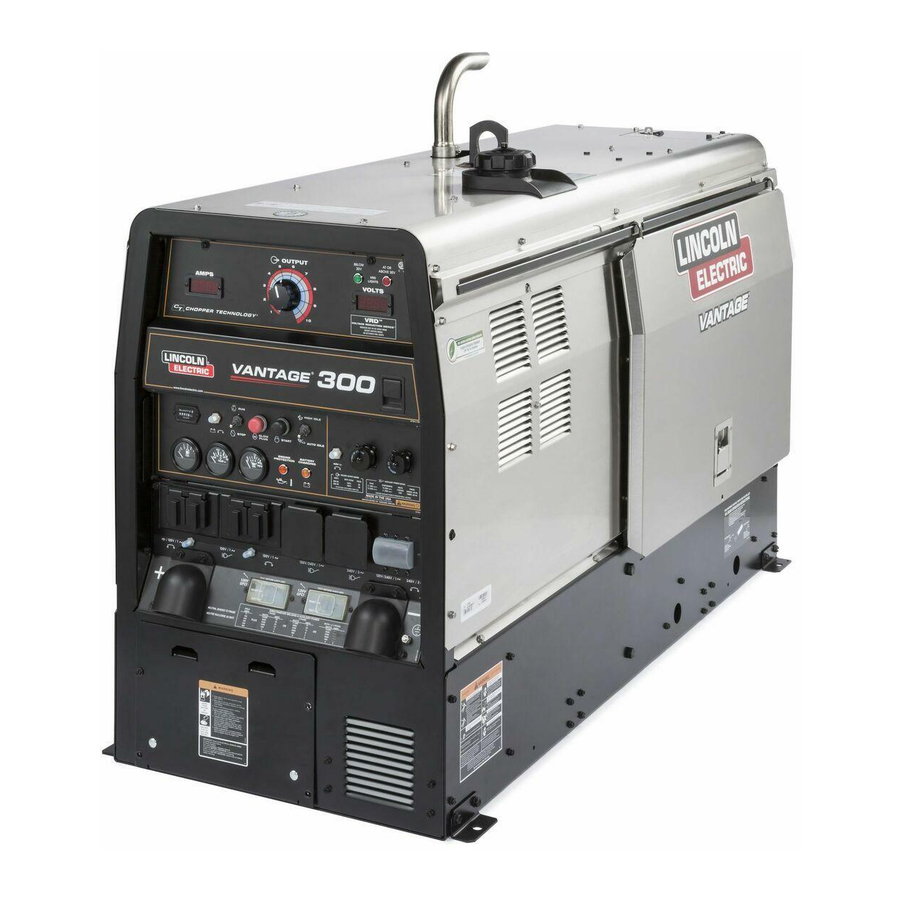
Lincoln Electric VANTAGE 300 Operator's Manual
Hide thumbs
Also See for VANTAGE 300:
- Specification sheet (168 pages) ,
- Technical specifications (8 pages) ,
- Operator's manual (54 pages)
Table of Contents
Advertisement
Quick Links
Operator's Manual
VANTAGE
Register your machine:
www.lincolnelectric.com/register
Authorized Service and Distributor Locator:
www.lincolnelectric.com/locator
Save for future reference
Date Purchased
Code: (ex: 10859)
Serial: (ex: U1060512345)
IM10211-A
| Issue D ate 07-15
© Lincoln Global, Inc. All Rights Reserved.
®
300
For use with machines having Code Numbers:
12384, 12508
Need Help? Call 1.888.935.3877
to talk to a Service Representative
Hours of Operation:
8:00 AM to 6:00 PM (ET) Mon. thru Fri.
After hours?
Use "Ask the Experts" at lincolnelectric.com
A Lincoln Service Representative will contact you
no later than the following business day.
For Service outside the USA:
Email: globalservice@lincolnelectric.com
Advertisement
Table of Contents
Troubleshooting

Related Manuals for Lincoln Electric VANTAGE 300


Summary of Contents for Lincoln Electric VANTAGE 300
- Page 1 Operator’s Manual ® VANTAGE For use with machines having Code Numbers: 12384, 12508 Need Help? Call 1.888.935.3877 Register your machine: to talk to a Service Representative www.lincolnelectric.com/register Authorized Service and Distributor Locator: Hours of Operation: www.lincolnelectric.com/locator 8:00 AM to 6:00 PM (ET) Mon. thru Fri. Save for future reference After hours? Use “Ask the Experts”...
- Page 2 THANK YOU FOR SELECTING A QUALITY PRODUCT BY KEEP YOUR HEAD OUT OF THE FUMES. DON’T get too close to the arc. LINCOLN ELEC TRIC. Use corrective lenses if necessary to stay a reasonable distance away from the arc. READ and obey the Safety Data PLEASE EXAMINE CARTON AND EQUIPMENT FOR Sheet (SDS) and the warning label DAMAGE IMMEDIATELY...
- Page 3 W117.2-1974. A Free copy of “Arc Welding Safety” booklet E205 is available from the Lincoln Electric Company, 2.d. All welders should use the following procedures in order to 22801 St. Clair Avenue, Cleveland, Ohio 44117-1199.
-
Page 4: Electric Shock Can Kill
SAFETY ELECTRIC SHOCK ARC RAYS CAN BURN. CAN KILL. 3.a. The electrode and work (or ground) circuits are 4.a. Use a shield with the proper filter and cover plates to protect your electrically “hot” when the welder is on. Do eyes from sparks and the rays of the arc when welding or not touch these “hot”... - Page 5 SAFETY WELDING AND CUTTING CYLINDER MAY EXPLODE IF SPARKS CAN CAUSE DAMAGED. FIRE OR EXPLOSION. 7.a. Use only compressed gas cylinders containing the correct shielding gas for the process used 6.a. Remove fire hazards from the welding area. If and properly operating regulators designed for this is not possible, cover them to prevent the welding sparks the gas and pressure used.
-
Page 6: Table Of Contents
Machine Grounding ............................A-6 Welding Terminals ............................A-6 Welding Output Cables ..........................A-7 Cable Installation............................A-7 Auxiliary Power ..............................A-7 Standby Power Connections ..........................A-7 Connection of Lincoln Electric Wire Feeders..................A-8, A-9 _________________________________________________________________________________________ Operation..............................Section B Safety Precautions ............................B-1 General Description............................B-1 For Auxiliary Power ............................B-1 Engine Operation...............................B-1 Add Fuel ................................B-1... -
Page 7: Table Of Contents
TABLE OF CONTENTS Page Maintenance ..........................Section D Safety Precautions ........................D-1 Routine Maintenance ........................D-1 Engine Service Items ........................D-1 Engine Oil Change ......................D-1, D-2 Engine Oil Filter Change ......................D-2 Air Cleaner ..........................D-2 Service Instructions And Installation Tips for Engine Air Filter............D-3 Cooling System..........................D-4 Tightening the Fan Belt......................D-4 Fuel ..............................D-4 Bleeding the Fuel System ......................D-4... - Page 8 NOTES...
-
Page 9: Technical Specifications
TECHNICAL SPECIFICATIONS - VANTAGE 300 (K2409-7) VANTAGE ® INSTALLATION ® INPUT - DIESEL ENGINE Description Make/Model Horsepower Operating Displacement cu. in. (ltrs.) Starting Capacities Systems @ 1800 RPM Speed (RPM) Bore x Stroke inch (mm) 12VDC Battery High Fuel: 20gal.(75.7L) and starter 1890 RPM Oil: 6.4qts.(6.0L) -
Page 10: Machine Specifications
VANTAGE ® INSTALLATION MACHINE SPECIFICATIONS RECEPTACLES AUXILIARY POWER CIRCUIT BREAKER OTHER CIRCUIT BREAKERS (1) 220V Euro Style (1) 16Amp for Single Phase and 3-Phase (3-pole) 10AMP for Engine Battery (1) 380V Euro Style Charging Circuit 10AMP for 42V Wire Feeder Power... -
Page 11: Safety Precautions
SAFETY PRECAUTIONS VANTAGE ® INSTALLATION FIGURE A.1 WARNING (VRD)-VOLTAGE REDUCTION DEVICE Do not attempt to use this equipment until you SWITCH IS LOCATED IN THIS AREA. have thoroughly read the engine manufacturer’s manual supplied with your welder. It includes important safety precautions, detailed engine starting, operating and maintenance instructions, and parts lists. -
Page 12: Lifting
VANTAGE ® INSTALLATION TOWING LIFTING The VANTAGE 300 weighs approximately 1190 lbs. ® (540kg.) with a full tank of fuel (1035 lbs. (470kg.) less Use a recommended trailer for use with this equipment for road, fuel). A lift bail is mounted to the machine and should in-plant and yard towing by a vehicle(1). -
Page 13: Pre-Operation Engine Service
ENGINE COOLING SYSTEM VANTAGE ® INSTALLATION PRE-OPERATION ENGINE SERVICE WARNING READ the engine operating and maintenance instruc- tions supplied with this machine. Air to cool the engine is drawn in the side and WARNING exhausted through radiator & case back. It is important that the intake and exhaust air is not •... -
Page 14: Remote Control
ELECTRICAL CONNECTIONS VANTAGE ® INSTALLATION REMOTE CONTROL The VANTAGE 300 is equipped with a 6-pin and a ® MACHINE GROUNDING 14-pin connector. When in the Arc Gouging or CV- WIRE modes and when a remote control is connected Because this portable engine driven welder creates its to the 6-pin Connector, the auto-sensing circuit auto- own power, it is not necessary to connect its frame to matically switches the OUTPUT control from control at... -
Page 15: Welding Output Cables
VANTAGE ® INSTALLATION AUXILIARY POWER WELDING OUTPUT CABLES With the engine off connect the electrode and work cables to the output studs. The welding process dic- The auxiliary power capacity is 10,500 watts Peak, tates the polarity of the electrode cable. These connec- 14,500 Watts Continuous of 60 Hz, single phase tions should be checked periodically and tightened with power. - Page 16 VANTAGE ® INSTALLATION 4. Control Cable Model: CONNECTION OF LINCOLN ELECTRIC WIRE FEEDERS • Connect Control Cable between Engine Welder and Feeder. Connection of LN-7 or LN-8 to the VANTAGE ® • Set the "WELD TERMINALS" switch to "REMOTELY CONTROLLED"...
- Page 17 VANTAGE ® INSTALLATION WARNING Spool Gun (K487-25) and Cobramatic to VAN- TAGE ® • Shut the welder off. Connection of the LN-25 to the VANTAGE ® Shut off welder before making any electrical con- nections. • Connect per instructions on the appropriate connec- ------------------------------------------------------------------------ tion diagram in Section F.
- Page 18 SAFETY PRECAUTIONS VANTAGE ® OPERATION Reinsert the dipstick and check the level on the dip- stick. WARNING • Add oil (if necessary) to bring the level up to the full mark. Do not overfill. Close engine door. • Check radiator for proper coolant level. (Fill if nec- Do not attempt to use this equipment until you essary).
- Page 19 VANTAGE ® OPERATION FIGURE B.1 WELDING CONTROLS (Figure B.1) PUT CONTROL is used to preset the voltage. When in the TOUCH START TIG mode and when an Amptrol is connected to the 6-Pin Connector, the OUT- 1. OUTPUT CONTROL- The OUTPUT dial is used to PUT dial is used to set the maximum current range of the preset the output voltage or current as displayed on the dig- CURRENT CONTROL of the Amptrol.
- Page 20 10. WIRE FEEDER VOLTMETER SWITCH: VANTAGE ® OPERATION 4. ARC CONTROL - The ARC CONTROL dial is active in Matches the polarity of the wire feeder voltmeter to the CV-WIRE, CC-STICK and DOWNHILL PIPE modes, the polarity of the electrode. and has different functions in these modes.
-
Page 21: Engine Controls
ENGINE CONTROLS: VANTAGE ® OPERATION 3e. BATTERY VOLTAGE INDICATOR 12. RUN/STOP SWITCH Displays the battery voltage and indicates that - RUN position ener- the charging system is functioning properly.. gizes the engine prior to starting. STOP posi- tion stops the engine. The oil pressure interlock switch 18. -
Page 22: Welder Operation
WELDER OPERATION VANTAGE ® OPERATION NOTE: Due to the low OCV with the VRD on, a very slight delay during striking of the electrodes may DUTY CYCLE occur. Due to the requirement of the resistance in the Duty Cycle is the percentage of time the load is being circuit to be low for a VRD to operate, a good metal- applied in a 10 minute period. -
Page 23: Tig Welding
VANTAGE ® OPERATION NOTE: With the VRD switch in the “ON” position there is Once the arc is started, normal welding technique for no output in the DOWNHILL PIPE mode. For indicator the application is then used. light operation, see Table B.1. TIG WELDING For other electrodes the above techniques should be tried first and varied as needed to suit operator prefer-... -
Page 24: Wire Welding-Cv
220 VAC or 380 VAC supply (not both at the same The VANTAGE 300 can be used for arc gouging. For optimal time). performance, set the MODE switch to ARC GOUGING. -
Page 25: Field Installed Options / Accessories
FIELD INSTALLED OPTIONS / ACCESSORIES VANTAGE ® ACCESSORIES rolls and inner wire guide for Steel Wires. (Used on LN-25 Pro) K2641-2 FOUR WHEELED STEERABLE YARD TRAILER For in plant and yard towing. Comes standard with a Duo-Hitch™, a K449 LN-25 - Includes internal contactor for across the arc opera- 2”... - Page 26 VANTAGE SAFETY PRECAUTIONS ® MAINTENANCE Routine Maintenance WARNING At the end of each day’s use, refill the fuel tank to minimize moisture condensation in the tank. Running • Have qualified personnel do all maintenance out of fuel tends to draw dirt into the fuel system. and troubleshooting work.
-
Page 27: Engine Service Items
VANTAGE ® MAINTENANCE Oil Filter Change • Close the drain valve by pushing in and twisting • Drain the oil. clockwise. Replace the cap. • Remove the oil filter with an oil filter wrench and • Re-fill the crankcase to the upper limit mark on the drain the oil into a suitable container. - Page 28 VANTAGE ® MAINTENANCE Service Instructions Service Instructions Single- and Two-Stage Engine Air Cleaners Single- and Two-Stage Engine Air Cleaners Inspect the New Filter for Damage Inspect the New Filter for Damage Remove the Filter Remove the Filter Inspect the new filter carefully, paying attention to Unfasten or unlatch the the inside of the open end, which is the service cover.
-
Page 29: Cooling System
VANTAGE ® MAINTENANCE FUEL COOLING SYSTEM WARNING DIESEL FUEL ONLY-Low sulphur fuel or ultra low sul- phur fuel in U.S.A. and Canada. HOT COOLANT can burn skin. At the end of each day’s use, refill the fuel tank to min- •... -
Page 30: Fuel Filter
VANTAGE ® MAINTENANCE CLEANING THE BATTERY FUEL FILTER Keep the battery clean by wiping it with a damp cloth 1. Check the fuel filter and fuel pre-filter for water when dirty. If the terminals appear corroded, discon- accumulation or sediment. nect the battery cables and wash the terminals with an ammonia solution or a solution of 1/4 pound (0.1113 2. -
Page 31: Storage
WARNING • Service and Repair should only be performed by Lincoln Electric Factory Trained Personnel. Unauthorized repairs performed on this equip- ment may result in danger to the technician and machine operator and will invalidate your factory warranty. -
Page 32: How To Use Troubleshooting Guide
HOW TO USE TROUBLESHOOTING GUIDE WARNING Service and Repair should only be performed by Lincoln Electric Factory Trained Personnel. Unauthorized repairs performed on this equipment may result in danger to the technician and machine operator and will invalidate your factory warranty. For your safety and to avoid Electrical Shock, please observe all safety notes and precautions detailed throughout this manual. - Page 33 VANTAGE ® TROUBLESHOOTING Observe all Safety Guidelines detailed throughout this manual PROBLEMS POSSIBLE RECOMMENDED (SYMPTOMS) CAUSE COURSE OF ACTION 1. Contact your local Lincoln Major Physical or Electrical Damage Authorized Field Service is Evident. Facility. Engine will not "crank". 1. Battery is low, Charge Battery. 2.
- Page 34 VANTAGE ® TROUBLESHOOTING Observe all Safety Guidelines detailed throughout this manual PROBLEMS POSSIBLE RECOMMENDED (SYMPTOMS) CAUSE COURSE OF ACTION Engine shuts down while under a 1. High radiator coolant tempera- load. ture. Reduce load if it is exceed- ing machine rating. Add coolant to system if low.
- Page 35 VANTAGE ® TROUBLESHOOTING Observe all Safety Guidelines detailed throughout this manual PROBLEMS POSSIBLE RECOMMENDED (SYMPTOMS) CAUSE COURSE OF ACTION Engine will not go to high idle when 1. Auxiliary power load is less than using auxiliary power. 100 watts. Idler may not respond with less than a 100 watt load.
- Page 36 VANTAGE ® TROUBLESHOOTING Observe all Safety Guidelines detailed throughout this manual PROBLEMS POSSIBLE RECOMMENDED (SYMPTOMS) CAUSE COURSE OF ACTION Engine does not develop full power. 1. Fuel filter dirty/clogged. Replace. Low weld and auxiliary output. 2. Air filter dirty/clogged. Replace Air Engine runs rough.
- Page 37 VANTAGE ® TROUBLESHOOTING Observe all Safety Guidelines detailed throughout this manual PROBLEMS POSSIBLE RECOMMENDED (SYMPTOMS) CAUSE COURSE OF ACTION No auxiliary power. 1. Open circuit breakers. Reset breakers. If breakers keep tripping reduce power draw. 2. Faulty connections to auxiliary receptacles.
- Page 38 VANTAGE ® DIAGRAMS...
- Page 39 VANTAGE ® DIAGRAMS...
- Page 40 VANTAGE ® DIAGRAMS...
- Page 41 VANTAGE ® DIAGRAMS...
- Page 42 VANTAGE ® DIAGRAMS...
- Page 43 VANTAGE ® DIAGRAMS...
- Page 44 VANTAGE ® DIAGRAMS...
- Page 45 VANTAGE ® DIAGRAMS...
- Page 46 VANTAGE ® DIAGRAMS...
- Page 47 VANTAGE ® DIAGRAMS F-10...
- Page 48 VANTAGE ® DIAGRAMS F-11...
- Page 49 VANTAGE ® NOTES...
- Page 50 THIS PAGE INTENTIONALLY LEFT BLANK...
- Page 51 Case Front & Control Panel Assembly P-892-D Output Panel Assembly P-892-E Power Module Panel Assembly P-892-F Generator & Rotor Assembly P-892-G Base Fuel Tank & Battery Assembly P-892-H Engine Assembly P-892-J Case Back & Radiator Asbly P-892-K Enclosure Components Vantage 300 (Kubota) - 12508...
- Page 52 Index of Sub Assemblies - 12508 P-892-A.jpg Vantage 300 (Kubota) - 12508...
- Page 53 9SS22061-4 SEALING BOOT 9SG8353 DECAL CARRIER 9SG7637-3 WELD CONTROL PC BD ASBLY 9SS8025-100 SELF TAPPING SCREW 9SL11924-1 PC BD MOUNTING BRKT 9ST9187-13 #10-24HLN-1817/1-NYLON INSERT 9SG8337 Wiring Harness 9ST13637-5 DIODE-BRIDGE35A800VF-W1-PH 9SS10773-7 INSULATING WASHER 9SS9262-3 PLAIN WASHER Vantage 300 (Kubota) - 12508...
- Page 54 9SS22061-3 SEALING BOOT 9SS9225-68 THREAD FORMING SCREW (CUTTING) 9SL13117-4 Case Front & Insert Asbly 9SG4865-4 Case Front 9SS9225-68 THREAD FORMING SCREW (CUTTING) 9SG4870 CASEFRONT INSERT 9SS9225-68 THREAD FORMING SCREW (CUTTING) 9SG6048-4 Shield 9SM17238 INSTRUCTION TAG Vantage 300 (Kubota) - 12508...
- Page 55 Case Front & Control Panel Assembly P-892-C.jpg Vantage 300 (Kubota) - 12508...
- Page 56 RECEPTACLE-230V 9SM20194-2 Circuit Breaker 9SG7594-2 BOOT 9SM22867 PARALLEL SWITCH 9SS28387-4 CIRCUIT BREAKER STRAP 9SS21130-50 PUSH BUTTONE-STOP IDEC 4NC 9ST14731-38 METRIC HEX HD SCREW-M6 X1.0 9SS9225-63 THREAD FORMING SCREW (CUTTING) 9SG8353 DECAL CARRIER 9SG8353 DECAL CARRIER Vantage 300 (Kubota) - 12508...
- Page 57 Output Panel Assembly P-892-D.jpg Vantage 300 (Kubota) - 12508...
- Page 58 9SCF000010 #10-24HN 9SS22168 HEAT SINK HOLDER 9SS9225-45 THREAD FORMING SCREW 9SL11132-2 THREE PHASE BRIDGE RECTIFIER 9SS9262-121 PLAIN WASHER 9SE106A-14 LOCKWASHER 9SS9225-68 THREAD FORMING SCREW (CUTTING) 9SL12400-3V1 IDLER/ENGINE SHUTDOWN PC BD ASBLY 9SS8025-100 SELF TAPPING SCREW Vantage 300 (Kubota) - 12508...
- Page 59 Power Module Panel Assembly P-892-E.jpg Vantage 300 (Kubota) - 12508...
- Page 60 PLAIN WASHER 9SM21315 BRUSH HOLDER & BRACKET ASBLY 9SM18323 BRUSH HOLDER BRKT 9SM16158 BRUSH & BRUSH HOLDER ASBLY 9SG2114 BRUSH HOLDER CARTRIDGE 9SS19480 BRUSH ASBLY 9SM16157 BRUSH ASBLY RETAINER 9ST12380-4 BUSHING 9SS9225-68 THREAD FORMING SCREW (CUTTING) Vantage 300 (Kubota) - 12508...
- Page 61 Generator & Rotor Assembly P-892-F.jpg Vantage 300 (Kubota) - 12508...
- Page 62 9SE106A-14 LOCKWASHER 9SCF000029 5/16-18HN 9SS9225-68 THREAD FORMING SCREW (CUTTING) 9SL8904-5 BATTERY & HOLD DOWN ASBLY 9SM9399-11 Battery 9SM20535 BATTERY TRAY 9SS22018 BATTERY BRKT 9ST11827-31 CARRIAGE BOLT 9ST9187-6 LOCKNUT 9ST14654 CAP-PLASTIC 9SS9225-68 THREAD FORMING SCREW (CUTTING) Vantage 300 (Kubota) - 12508...
- Page 63 OUTPUT STUD COVER 9SS25669 OUTPUT STUD COVER PLATE 9SS9225-68 THREAD FORMING SCREW (CUTTING) 9SS25455 OIL DRAIN DECAL 9SM16197 DECAL-WARNING 9SS17851 DECAL-CAUTION 9SL12515-1 SIDE PANEL 9SS24739-27 1/4X.75 TEK SCREW 9SL12457 SUPPORT RAIL 9SS9225-68 THREAD FORMING SCREW (CUTTING) Vantage 300 (Kubota) - 12508...
- Page 64 Base, Fuel Tank & Battery Assembly PART NUMBER DESCRIPTION 9SM20612 CONTAINER BRACKET 9SS9225-68 THREAD FORMING SCREW (CUTTING) Vantage 300 (Kubota) - 12508...
- Page 65 Base, Fuel Tank & Battery Assembly P-892-G.jpg Vantage 300 (Kubota) - 12508...
- Page 66 THREAD FORMING SCREW (CUTTING) 9SS22070 IN-LINE SWIVEL 9SCF000060 1/4-28HJN 9SS22232 ROD END SWIVEL 9SCF000015 1/4-20X1.00HHCS 9SE106A-2 LOCKWASHER 9SCF000017 1/4-20HN 9SS30694-2 IN-LINE FUEL FILTER 9SS15286-1 CLAMP 9SS9225-64 SELF TAPPING SCREW 9SS9225-66 SELF TAPPING SCREW 9ST10642-229 FLEX TUBE Vantage 300 (Kubota) - 12508...
- Page 67 9SCF000029 5/16-18HN 9SM19801-1A OIL FILTER ELEMENT 9SS9225-68 THREAD FORMING SCREW (CUTTING) 9SS26066 WATER SEPARATOR BRKT 9SS9225-68 THREAD FORMING SCREW (CUTTING) 9SCF000187 5/16-18X2.50HHCS 9SE106A-14 LOCKWASHER 9SCF000029 5/16-18HN 9ST10642-111 FLEX TUBE 9ST13777-1 HOSE CLAMP 9SS10888-35 HOSE CLAMP Vantage 300 (Kubota) - 12508...
- Page 68 Engine Assembly P-892-H.jpg Vantage 300 (Kubota) - 12508...
- Page 69 9SS9225-68 THREAD FORMING SCREW (CUTTING) 9SG4060-6 LEFT FAN GUARD 9SS9225-68 THREAD FORMING SCREW (CUTTING) 9SG8353 DECAL CARRIER 9SS26073 ENGINE SERVICE DECAL 9ST13086-62 DECAL-WARNING 9ST14882 DOOR BUMPER 9SS25514 COOLANT BOTTLE BRACKET 9SS9225-68 THREAD FORMING SCREW (CUTTING) Vantage 300 (Kubota) - 12508...
- Page 70 Case Back & Radiator Asbly P-892-J.jpg Vantage 300 (Kubota) - 12508...
- Page 71 EDGE GUARD 9SL13813 DOOR ASBLY 9SL12513-1 Door 9SM20241 DOOR LATCH 9ST12584-6 RIVET 9ST14882-2 DOOR BUMPER 9ST14882 DOOR BUMPER 9SS27368-6 LOGO DECAL 9SM21801 FAMILY NAME LOGO 9SS12934-1 COVER SEAL 9SS30277-3 WARRANTY DECAL 9SM21436 CARBON MONOXIDE WARNING DECAL Vantage 300 (Kubota) - 12508...
- Page 72 Enclosure Components PART NUMBER DESCRIPTION 9SS28039-3 DECAL GREEN INITIATIVE Vantage 300 (Kubota) - 12508...
- Page 73 Enclosure Components P-892-K.jpg Vantage 300 (Kubota) - 12508...
- Page 74 WARNING Do not touch electrically live parts or Keep flammable materials away. Wear eye, ear and body protection. electrode with skin or wet clothing. Insulate yourself from work and AVISO DE ground. Spanish PRECAuCION No toque las partes o los electrodos Mantenga el material combustible Protéjase los ojos, los oídos y el bajo carga con la piel o ropa moja-...
- Page 75 WARNING Keep your head out of fumes. Turn power off before servicing. Do not operate with panel open or Use ventilation or exhaust to guards off. remove fumes from breathing zone. AVISO DE Spanish PRECAuCION Los humos fuera de la zona de res- Desconectar el cable de ali- No operar con panel abierto o piración.
- Page 76 Lincoln Electric for advice or information about their use of our products. We respond to our customers based on the best information in our possession at that time. Lincoln Electric is not in a position to warrant or guarantee such advice, and assumes no liability, with respect to such information or advice.