Table of Contents

Related Manuals for Panasonic BY-HPE11KTA


Summary of Contents for Panasonic BY-HPE11KTA
- Page 1 Installation Guide Coaxial - LAN Converter with PoE function Indoor Use Only BY-HPE11KTA Model No. Before attempting to connect or operate this product, please read these instructions carefully and save this manual for future use.
- Page 2 With the built-in PoE function, the BY-HPE11KTA is able to supply power to Panasonic network cameras, which eliminates the need for installing power outlets for the cameras.
- Page 3 No setup required Connections can be established by simply connecting the coaxial cable to the coaxial - LAN converter. When connected to a Panasonic network camera. For other cameras the connection distance is 300 m (984 feet 3 inches). Measured using Linux FTP.
- Page 4 OR THE CORRESPONDING PRODUCT (S). Disclaimer of warranty IN NO EVENT SHALL Panasonic System Networks Co., Ltd. BE LIABLE TO ANY PARTY OR ANY PERSON, EXCEPT FOR REPLACEMENT OR REASONABLE MAINTENANCE OF THE PRODUCT, FOR THE CASES, INCLUDING BUT NOT LIMITED TO BELOW: 1.
- Page 5 Other Information 2. PERSONAL INJURY OR ANY DAMAGE CAUSED BY INAPPROPRIATE USE OR NEGLIGENT OPERATION OF THE USER; 3. UNAUTHORIZED DISASSEMBLE, REPAIR OR MODIFICATION OF THE PRODUCT BY THE USER; 4. INCONVENIENCE OR ANY LOSS ARISING WHEN IMAGES ARE NOT DISPLAYED, DUE TO ANY REASON OR CAUSE INCLUDING ANY FAILURE OR PROBLEM OF THE PRODUCT;...
- Page 6 Other Information • For security, reset the unit when sending the unit for servicing, discarding the unit, or giving the unit to someone else (see 2 Resetting the Unit in the Operating Instructions on the CD-ROM). • The unit does not have a firewall feature. To prevent unauthorized external access to the network, we recommend performing the following procedures.
- Page 7 Included Items Included Items Confirm that the following items are included in the unit’s packaging. • Installation Guide (this document) (1 pc.) • Warranty Card (1 pc.) • CD-ROM (1 pc.) • AC Cord (1 pc.) • Safety Wire (1 pc.) •...
- Page 8 For Your Safety For Your Safety To prevent severe injury and loss of life/property, read this section carefully before using the unit to ensure proper and safe operation of your unit. WARNING Consult an authorized dealer for mounting • Experience and knowledge are required to perform mounting of the unit. Incorrect mounting can cause damage to the unit, fire, electric shock, or injury.
- Page 9 For Your Safety Do not touch the unit, LAN cable, coaxial cable, AC cord, or power plug during thunderstorms • This may result in electric shock. Do not use the included AC cord with other devices • This may result in electric shock or fire. Only use the included AC cord •...
- Page 10 For Your Safety Turn the power off before performing wiring • This may result in electric shock, or result in fire from wiring shorts or incorrect wiring. Only use mounting brackets made for the unit • Serious damage and/or injury may result if the unit falls. Do not damage coaxial cables, insert objects into the conductor, or connect coaxial cables with incomplete relays •...
- Page 11 For Your Safety Do not mount the unit to ceilings or walls made of soft materials • Do not mount the unit to soft ceilings or walls such as plasterboard, ALC (aerated light-weight concrete), concrete blocks, or any surfaces under 25 mm (1 inch) thickness.
- Page 12 Important Safety Instructions Important Safety Instructions When using this unit, basic safety precautions should always be followed to reduce the risk of fire, electric shock, or personal injury. 1. Do not use this unit near water for example, near a bathtub, washbowl, kitchen sink, or laundry tub, in a wet basement or near a swimming pool.
- Page 13 FCC Information FCC Information This equipment has been tested and found to comply with the limits for a Class A digital device, pursuant to part 15 of the FCC Rules. These limits are designed to provide reasonable protection against harmful interference when the equipment is operated in a commercial environment.
- Page 14 General Precautions General Precautions Follow the instructions written in For Your Safety (see page 8) and Important Safety Instructions (see page 12) together with the instructions written below. 1. The unit is intended for indoor use only and should not be mounted outdoors. 2.
- Page 15 Precautions for Installation Precautions for Installation All electrical wiring should be performed by a qualified electrician. Consult an authorized dealer for installation. 1. The unit is intended for indoor use only • The unit cannot be used outdoors. Do not install the unit in areas that are exposed to direct sunlight for long periods of time, or areas near heaters or air conditioners.
- Page 16 Precautions for Installation Mark points where you are going to make holes (2 places) according to the position of the camera adaptor. ii. Mark a point where you are going to make a hole (1 place) for the safety wire. iii.
- Page 17 Precautions for Installation RG-6/U coaxial cable Maximum Cable DC R/300 m (984 Maximum Cable Coaxial Cable Length (for feet 3 inches) of Length (for PoE Type non-PoE Inner Conductor connections) connections) Less than 12 W RG-6/U 500 m (1,640 feet 5 2,000 m (6,561 feet inches) 8 inches)
-
Page 18: Table Of Contents
Table of Contents Table of Contents Main Unit ....................19 Camera Adaptor (BY-HPE11R) ..............19 Center Adaptor (BY-HPE11H) ................21 Understanding the Indicators ...............22 Mounting the Unit ..................23 Mounting the Camera Adaptor ..............23 Mounting the Center Adaptor to a Rack ............25 Connecting the Unit .................28 Connection Example ..................28 Connections ....................29 Installation Guide... -
Page 19: Main Unit
1 Main Unit 1 Main Unit 1.1 Camera Adaptor (BY-HPE11R) Front view A Indicator Displays the status of the camera adaptor (see page 22). B PoE switch Turns the PoE function ON/OFF. The default setting is [ON]. IMPORTANT • When using the camera adaptor’s PoE function to supply power to a network camera, set the PoE switch to [ON]. - Page 20 1 Main Unit Rear view A Used when attaching the camera adaptor to a ceiling or wall with screws (see page 24). B Used when attaching the safety wire (see page 23). C Used when attaching the camera adaptor to screws inserted into a wall.
-
Page 21: Center Adaptor (By-Hpe11H)
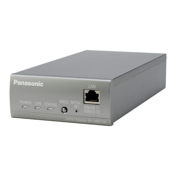
1 Main Unit 1.2 Center Adaptor (BY-HPE11H) Front view A Indicators Displays the status of the center adaptor (see page 22). B SPEED button Used when measuring the speed between adaptors (see page 33). C INITIAL SET button Used to reset the center adaptor to its factory default settings (see 2.2 Resetting Center Adaptors in the Operating Instructions on the... -
Page 22: Understanding The Indicators
1 Main Unit 1.3 Understanding the Indicators The light indicators change depending on the operating status of the camera and center adaptors. Camera adaptor Indicator Light Status Meaning Green (lit) The camera adaptor is connected to the center adaptor. Orange (lit) The camera adaptor is activating. -
Page 23: Mounting The Unit
2 Mounting the Unit 2 Mounting the Unit 2.1 Mounting the Camera Adaptor Please read the following information before mounting the camera adaptor. IMPORTANT • Mount the camera adaptor to a secure area. • Mount the camera adaptor and safety wire to secure part of the ceiling or wall such as a crossbeam. - Page 24 2 Mounting the Unit 2. Secure the camera adaptor to the wall or ceiling using screws (customer-provided, length: 20 mm [13/16 inches], body diameter: 4 mm [3/16 inches]). • Use screws that are appropriate for the material of the ceiling or wall. Screw (customer-provided, length: 20 mm [13/16 inches], body diameter: 4 mm [3/16 inches])
-
Page 25: Mounting The Center Adaptor To A Rack
2 Mounting the Unit 2.2 Mounting the Center Adaptor to a Rack By using the Rack Mount Connecting Fitting (sold separately), 3 or 4 connected center adaptors can be mounted to a rack. Prepare the Rack Mount Connecting Fitting (BY-HCA10A), which includes the following items. - Page 26 2 Mounting the Unit • Connecting 4 center adaptors (Recommended torque 0.4-1.0 N·m {4.1-10.2 kgf·cm}) Screw (Flat-head M3x6: 32 pcs.) Underside continuous connecting bracket 2. Secure the BY-HCA10A mounting brackets to both sides of the connected center adaptors with the screws included with the BY-HCA10A. (Recommended torque 0.4-1.0 N·m {4.1-10.2 kgf·cm}) Mounting bracket Screw...
- Page 27 2 Mounting the Unit 3. Secure the connected center adaptors to the rack. • Securely mount the center adaptors to the rack with the rack mounting screws (customer-provided, nominal diameter 5 mm [3/16 inches] tapping). • We recommend using a fan or other device to keep the temperature in the rack under 30 °C (86 °F).
-
Page 28: Connecting The Unit
3 Connecting the Unit 3 Connecting the Unit 3.1 Connection Example Network camera Camera adaptor Center adaptor Switching hub (or similar device) Network device LAN cable Coaxial cable – Connect network cameras and camera adaptors with LAN cables. – Connect camera adaptors and center adaptors with coaxial cables. –... -
Page 29: Connections
3 Connecting the Unit • When connecting to network cameras not made by Panasonic, the PoE function may not be able to supply power using cross-pair LAN cables. Confirm the specifications of the network camera used before installation. 3.2 Connections Before proceeding with the connections, turn off the power of the unit and other network devices that will be connected. - Page 30 3 Connecting the Unit 2. First pass the coaxial cable through the included BNC connector cover, then connect the coaxial cable to the BNC connector of the camera adaptor. Coaxial cable BNC connector (When using an existing cable, you must disconnect it from another device before connecting.) BNC connector cover Connect to the center adaptor.
- Page 31 3 Connecting the Unit 3. Secure the BNC connector cover with the included screw to the camera adaptor. (Recommended torque 0.4-0.8 N·m {4.1-8.2 kgf·cm}) Screw (length: 10 mm [3/8 inches], body diameter: 2.6 mm [1/8 inches]) BNC connector cover 4. First pass the coaxial cable through the included BNC connector cover, then connect the coaxial cable to the BNC connector of the center adaptor.
- Page 32 3 Connecting the Unit 5. Secure the BNC connector cover with the included screw to the center adaptor. (Recommended torque 0.4-0.8 N·m {4.1-8.2 kgf·cm}) BNC connector cover Screw (length: 10 mm [3/8 inches], body diameter: 2.6 mm [1/8 inches]) 6. Connect a LAN cable (Cat-5e or higher) to the center adaptor and network device. Network connector Network device Network connector...
- Page 33 3 Connecting the Unit 8. Turn the power on for the network cameras and network devices, then check the indicators of the adaptors. Green Green Green Green 9. Press the center adaptor’s SPEED button for about 1 second. SPEED button POWER COAXIAL •...
- Page 34 3 Connecting the Unit 10. Confirm that all 3 of the center adaptor’s indicators are lit (for about 6 seconds). POWER LAN COAXIAL (Green) (Green) (Green) Installation Guide...
- Page 35 Notes Installation Guide...
- Page 36 For customer support, call 1.800.528.6747 Three Panasonic Way, Secaucus, New Jersey 07094 U.S.A. 5770 Ambler Drive, Mississauga, Ontario, L4W 2T3 Canada (905)624-5010 www.panasonic.ca © Panasonic System Networks Co., Ltd. 2010 Printed in Malaysia PNQX3079ZA KK1110MJ0...