Table of Contents
Advertisement
Quick Links
Download this manual
See also:
Operator's Manual
Advertisement
Table of Contents
Troubleshooting

Related Manuals for Furuno FM-4800


Summary of Contents for Furuno FM-4800
- Page 1 OPERATOR'S MANUAL MARINE VHF RADIOTELEPHONE FM-4800 Model www.furuno.com...
- Page 2 Electrical shock can result. power at the switchboard and contact a FURUNO service technician. Use the correct fuse. Use of the wrong fuse can cause fire or Do not use high-pressure cleaners to electrical shock.
- Page 3 SAFETY INSTRUCTIONS WARNING This transmitter must not be co-located or operating in conjunction with any other antenna or transmitter. Turn off the power at the mains Note: This equipment has been tested switchboard before beginning the and found to comply with the FCC installation.
- Page 4 Standard Steering compass compass ISEDC exposition aux radiations: 0.65 m 0.40 m FM-4800 0.70 m 0.45 m HS-4800 Cet équipement est conforme avec SP-4800 2.65 m 1.75 m ISEDC les limites d'exposition aux rayonnements définies pour un contrôlé...
- Page 5 How to discard a used battery Some FURUNO products have a battery(ies). To see if your product has a battery, see the chap- ter on Maintenance. Follow the instructions below if a battery is used. Tape the + and - terminals of battery before disposal to prevent fire, heat generation caused by short circuit.
-
Page 6: Table Of Contents
FM-4800 Operator’s Manual Contents Contents FOREWORD ................... 1 SYSTEM CONFIGURATION ............3 1. GETTING STARTED ..............4 1.1 Emergency Call (CH16) .................. 4 1.2 How to Call another Channel (CH16 or CH9) ..........4 1.3 Channels 13 and 67 (USA Channel Group only) ..........5 2. - Page 7 Contents FM-4800 Operator’s Manual 5. CHANNEL WATCH ..............40 5.1 Dual Channel ....................40 5.2 Triple Channel ....................40 6. SCAN ..................42 6.1 Scan All ......................42 6.2 Scan All + 16 ....................42 6.3 Memory Scan ....................42 6.4 Memory Scan + 16 ..................
- Page 8 FM-4800 Operator’s Manual Contents 10.7 Fog Horn Frequency ................... 65 10.8 Service Menu ....................65 11. CHANNEL FUNCTION SETUP ..........66 11.1 Channel Group .................... 66 11.2 Second Priority Channel ................66 11.3 Edit Channel Name ..................67 11.4 Private Channel ................... 68 12.
- Page 9 Contents FM-4800 Operator’s Manual 15.4.7 NMEA2000 Connector (CAN bus connector) ........95 15.4.8 Extension Cable (Optional) ............... 95 CHANNEL ASSIGNMENTS ............97 MENU TREE ................106 SPECIFICATIONS ..............109 PACKING LIST ................112 OUTLINE DRAWINGS ..............116 INTERCONNECTION ..............123...
-
Page 10: Foreword
FOREWORD FOREWORD A Word to the Owner of the FM-4800 FURUNO Electric Company thanks you for purchasing the FM-4800 Marine VHF Radiotelephone. We are confident you will discover why the FURUNO name has become synonymous with quality and reliability. Since 1948, FURUNO has enjoyed an enviable reputation for quality and reliability throughout the world. - Page 11 FOREWORD FM-4800 Operator’s Manual Program No.: FM-4800 : 0550257-01.**; HS-4800 : 0550259-01.**. (** denotes minor modifications.) CE declaration With regards to CE declarations, please refer to our website (www.furuno.com), for further information about RoHS conformity declarations.
-
Page 12: System Configuration
FM-4800 Operator’s Manual SYSTEM CONFIGURATION SYSTEM CONFIGURATION HANDSET SPEAKER HS-4800 SP-4800 NavNet TZtouch/2 VHF ANT EXTENSION NMEA2000 CABLE 12VDC External Speaker Horn Speaker EQUIPMENT NMEA0183 MARINE VHF RADIOTELEPHONE FM-4800 MICROPHONE Standard Supply MIC-4800 Optional Supply Local Supply... -
Page 13: Getting Started
The total transmission should be within one minute. The FM-4800 has DSC Distress calling, which can send a distress call digitally to all ships with compatible DSC radios. For more information, see section 4 DIGITAL SELECTIVE CALLING. ... -
Page 14: Channels 13 And 67 (Usa Channel Group Only)
FM-4800 Operator’s Manual GETTING STARTED The use of CH16 or CH9 should be limited to making initial contact only. A call should be within 1 minute, but can be repeated at a 2-minute interval. Before contact another vessel, refer to the channel charts in the Appendix and select a proper channel (working channel) for use after initial contact. -
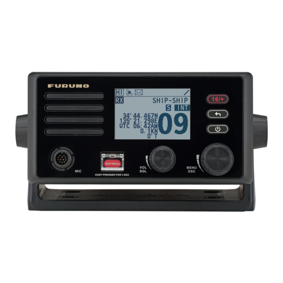
Page 15: Controls
CONTROLS FM-4800 Operator’s Manual 2. CONTROLS This section describes the controls of the radio FM-4800, the microphone MIC-4800, the handset HS-4800. 2.1 Radio Description [DISTRESS]: Distress Key Short press: Enter the distress nature selection and position manual input menu ... - Page 16 FM-4800 Operator’s Manual CONTROLS Description [MENU/DSC]: Menu / Digital Selective Calling (DSC) Control On the home screen: Press: Enter "MAIN MENU" Rotate: Switch to a channel On other screens: Press: Select item or confirm the selection ...
-
Page 17: Microphone
CONTROLS FM-4800 Operator’s Manual 2.2 Microphone Description [PTT]: Push-to-Talk Key Press and hold the key in radio mode to enable the radio for voice communication. Note When the PTT key on the microphone is pressed continuously, transmission time is limited to five minutes. This limits unintentional transmissions due to a stuck PTT key. -
Page 18: Handset
FM-4800 Operator’s Manual CONTROLS 2.3 Handset Description [PTT]: Push-to-Talk Key The transmitter is enabled for voice communications with another vessel. Note When the PTT key on the microphone is pressed continuously, transmission time is limited to five minutes. This limits unintentional transmissions due to a stuck PTT key. - Page 19 CONTROLS FM-4800 Operator’s Manual Description [VOL/SQL]: Volume / Squelch Control Press the key to switch between the volume adjust screen and the squelch adjust screen. [HI/LO]: High / Low Power Switch Press the switch to toggle between 25 W (High) and 1 W (Low).
-
Page 20: Home Screen
FM-4800 Operator’s Manual HOME SCREEN 3. HOME SCREEN Description : indicates high power such as 25 W. : indicates low power such as 1 W. : indicates internal and External GNSS. This icon disappears if there is no GNSS data. - Page 21 HOME SCREEN FM-4800 Operator’s Manual Description Display location information including longitude, latitude, time, COG, and SOG. If there is no any information, it displays "NO GNSS DATA". Note There are three sensors including built-in sensor, NMEA2000 and NMEA0183. The last two are external sensors. Their priorities in...
-
Page 22: Digital Selective Calling
FM-4800 Operator’s Manual DIGITAL SELECTIVE CALLING 4. DIGITAL SELECTIVE CALLING 4.1 General Digital Selective Calling (DSC) is a semi-automated method to establish a radio call. DSC has been designated by the International Maritime Organization (IMO) as an international standard for establishing VHF, MF and HF radio calls. It has also been designated as a part of the Global Maritime Distress and Safety System (GMDSS). -
Page 23: Dsc Distress Call
Menu/DSC control, automatically return to the Step 3. 4.3 DSC Distress Call FM-4800 can send and receive DSC distress calls. When FM-4800 receives GNSS signals, FM-4800 can also transmit the latitude and longitude of the vessel together with the DSC distress call. 4.3.1... - Page 24 Step 4 Initiate a DSC distress call with the nature of distress specified The FM-4800 is capable of transmitting a DSC distress call with the following distress categories: Undesignated, Fire, Flooding, Collision, Grounding, Listing, Sinking, Adrift, Abandoning, Piracy, and MOB (Man Overboard).
- Page 25 3.5-to-4.5-minute intervals until the call is canceled by the user, until an acknowledgement is received, or until the radio is turned off. The FM-4800 has a provision to pause the retransmitting of the distress call. To pause the distress call, select "PAUSE".
-
Page 26: How To Receive A Dsc Distress Call
FM-4800 Operator’s Manual DIGITAL SELECTIVE CALLING Press and hold the PTT key to announce your situation. Step 4 All stations. (Repeat 3 times) This is (Own ship name & call sign). MMSI 123456789 Our position is 09°12.1234’ N, 123°45.1234’ E. -
Page 27: How To Initiate An Individual Call
DIGITAL SELECTIVE CALLING FM-4800 Operator’s Manual Caution To make a DSC individual call, the radio of the receiving party should be set to manually acknowledge the individual call request from the initiating party. Otherwise, the radio of the receiving party will automatically send an "unable to acknowledge"... - Page 28 FM-4800 Operator’s Manual DIGITAL SELECTIVE CALLING Icon indicates the alias of the contact. If the called party is added in the call list, the alias will appear here. When the radio receives an acknowledgement, an alarm sounds and the Step 5 working channel changes to the channel selected in Step 3.
-
Page 29: How To Receive An Individual Call
DIGITAL SELECTIVE CALLING FM-4800 Operator’s Manual When the radio receives an acknowledgement, an alarm sounds and the Step 5 working channel changes to the channel selected in Step 3. Select "OK" on the screen. Press and hold the PTT key to talk into the microphone. - Page 30 FM-4800 Operator’s Manual DIGITAL SELECTIVE CALLING PAUSE: Select the soft key to pause the call and timing and temporarily disable automatic switching to the requested channel. You can resume the call by pressing the "RESUME" soft key. Select "ACCEPT".
-
Page 31: Group Call
DIGITAL SELECTIVE CALLING FM-4800 Operator’s Manual ACCEPT: Select the soft key to continue with the call and switch to the requested channel. REJECT: Select the soft key to reject the call. After you select "REJECT", select a reason for rejecting the call, and then an "UNABLE ACK"... - Page 32 FM-4800 Operator’s Manual DIGITAL SELECTIVE CALLING Register a group call On the home screen, press the Menu/DSC control to enter the "MAIN Step 1 MENU" screen. Go to "DSC SETUP > GROUP DIRECTORY". Step 2 Select "ADD ENTRY" to register a group.
-
Page 33: How To Receive A Group Call
DIGITAL SELECTIVE CALLING FM-4800 Operator’s Manual Initiate a group call from the "RECENT CALLS" On the "GROUP" page, select "RECENT CALLS". Step 1 Select a group, and then press the Menu/DSC control to enter the Step 2 "SELECT CH" page. - Page 34 FM-4800 Operator’s Manual DIGITAL SELECTIVE CALLING Cancel: Select the soft key to cancel the automatic channel switching. The radio returns to the home screen and the channel remains unchanged. PAUSE: Select the soft key to pause the call and timing. You can resume the call by pressing the "RESUME"...
-
Page 35: All Ships Call
DIGITAL SELECTIVE CALLING FM-4800 Operator’s Manual 4.6 All Ships Call This feature allows you to initiate a safety call or an urgency call to DSC-equipped vessels without having their MMSIs in the directory or receive a safety call or an urgency call. -
Page 36: How To Receive An All Ships Call
FM-4800 Operator’s Manual DIGITAL SELECTIVE CALLING Select "OK" to return to the home screen. Step 6 Press and hold the PTT key to talk into the microphone. Step 7 4.6.2 How to Receive an All Ships Call The channel change of your radio has two modes: "AUTO" and "MANUAL". Different channel change modes lead to different operations when you receive an All Ships call. -
Page 37: Position Request Call
DIGITAL SELECTIVE CALLING FM-4800 Operator’s Manual PAUSE: Select the soft key to pause the call and timing and temporarily disable automatic switching to the requested channel. You can resume the call by pressing the "RESUME" soft key. Note If no key is pressed within 10 seconds, the radio automatically switches to the requested channel. -
Page 38: How To Initiate A Position Request Call
FM-4800 Operator’s Manual DIGITAL SELECTIVE CALLING 4.7.1 How to Initiate a Position Request Call Enter the position request page On the home screen, press the Menu/DSC control to enter the "MAIN Step 1 MENU" page on the screen. Step 2 Go to "DSC CALL >... - Page 39 DIGITAL SELECTIVE CALLING FM-4800 Operator’s Manual Note If you receive an ACK from a ship that does not have location information, it would be easier to understand that it is expressed as "NO INFO" rather than "receive false position information".
-
Page 40: How To Receive A Position Request Call
FM-4800 Operator’s Manual DIGITAL SELECTIVE CALLING Initiate position request call by manually entering an MMSI number On the "POS REQUEST" page, select "MANUAL ID". Step 1 Rotate and press the Menu/DSC control to enter the MMSI of an individual Step 2 contact, and then press the Menu/DSC control. - Page 41 DIGITAL SELECTIVE CALLING FM-4800 Operator’s Manual When "POSITION ACK" is set to "MANUAL" When a DSC position request call is received, the alarm sounds. Rotate Step 1 the Menu/DSC control to stop the alarm. Step 2 Select "REPORT" to send your position.
-
Page 42: Auto Position Polling
FM-4800 Operator’s Manual DIGITAL SELECTIVE CALLING 4.8 Auto Position Polling This feature allows FM-4800 to automatically send a position request call at certain intervals. This feature must first be enabled from the "ACTIVATION" menu, then the vessel addresses must be set from the "SELECT ADDRESS" menu. -
Page 43: Calls
DIGITAL SELECTIVE CALLING FM-4800 Operator’s Manual 4.8.2 How to Select Vessels to Which the Radio Sends Auto Position Request Calls On the home screen, press the Menu/DSC control to enter the "MAIN Step 1 MENU" screen. Go to "DSC CALL > AUTO POS POLLING". -
Page 44: Dsc Log
The FM-4800 can store logs for the latest 40 received distress calls, the latest 10 received position request calls, the latest 40 received other calls, the latest 40 transmitted calls, and the latest 10 transmitted acknowledges. -
Page 45: Dsc Test
DIGITAL SELECTIVE CALLING FM-4800 Operator’s Manual Select a log you want to view. Step 5 You can initiate the call again or delete the log by pressing the "CALL" or "DELETE" soft key on the screen. 4.10 DSC Test This feature allows you to test whether your DSC radio can communicate normally with another DSC radio. - Page 46 FM-4800 Operator’s Manual DIGITAL SELECTIVE CALLING Initiate a DSC test call to a vessel registered in the individual directory Before you initiate a DSC test call from the individual directory, a vessel or person's name and the MMSI number associated with the vessel you want to transmit the call to should be added to the individual directory.
- Page 47 DIGITAL SELECTIVE CALLING FM-4800 Operator’s Manual When the radio receives an acknowledgement, an alarm sounds and the Step 4 following page appears. It means the radio you called has received the call. Select "OK" to return to the previous screen.
- Page 48 FM-4800 Operator’s Manual DIGITAL SELECTIVE CALLING Initiate a DSC test call by manually entering an MMSI number On the "DSC TEST" page, rotate and press the Menu/DSC control to Step 1 select "MANUAL ID". Step 2 Rotate and press the MENU/DSC control to enter the MMSI of a vessel that you want to contact.
-
Page 49: Channel Watch
CHANNEL WATCH FM-4800 Operator’s Manual 5. CHANNEL WATCH 5.1 Dual Channel Dual channel scans two channels for communications. One channel is a normal VHF channel and the other is CH16. The following is how the DUAL CH feature works when a signal is received on one of the channel: ... - Page 50 FM-4800 Operator’s Manual CHANNEL WATCH If a signal is received on CH16, the radio stops and listens only to CH16 until communication ends and then starts TRIPLE CH scan again. For information about how to set the second priority channel, see section 11.2 Second Priority Channel.
-
Page 51: Scan
SCAN FM-4800 Operator’s Manual 6. SCAN This feature allows you to select a scan mode to find the broadcasting channels. The available scan modes are as follows: SCAN ALL, SCAN ALL + 16, MEMORY SCAN, and MEMORY SCAN + 16. -
Page 52: Memory Scan + 16
FM-4800 Operator’s Manual SCAN 6.4 Memory Scan + 16 Memory Scan + 16 mode scans all memory channels in sequence, and checks CH16 after each programmed channel. Note Before you enable the Memory Scan +16 mode, at least one channel should be set as the memory channel. - Page 53 SCAN FM-4800 Operator’s Manual On the home screen, press the Menu/DSC control to enter the "MAIN Step 1 MENU" screen. Step 2 Go to "SCAN > EDIT MEMORY CH > ALL OFF". "MEM" icons disappear on the display. Press the Back key to return to the previous screen.
-
Page 54: Weather Mode
FM-4800 Operator’s Manual Weather Mode 7. Weather Mode When the product works on the USA or CAN channel, the weather mode is enabled. In this case, you can monitor the weather report from National Oceanographic and Atmospheric Administration (NOAA). For information about how to select a Channel Group (USA or Canada), see section 11.1. - Page 55 Weather Mode FM-4800 Operator’s Manual Select ON or OFF to enable or disable the feature. Step 3 Press the Menu/DSC control to save the setting and return to the previous Step 4 page.
-
Page 56: Fog Horn/Hailer/Intercom
FM-4800 Operator’s Manual Fog Horn/Hailer/Intercom 8. Fog Horn/Hailer/Intercom Note When receiving DSC calls in the Fog Horn mode or the Hailer mode, the radio exits the Fog Horn mode or the Hailer mode and enters the call receiving page. 8.1 Fog Horn This feature sounds certain international standard fog horn tones through the speaker. - Page 57 Fog Horn/Hailer/Intercom FM-4800 Operator’s Manual To stop the fog horn, release the PTT key. Step 3 Press the Back key to return to the previous screen. Step 4 Use the manual yelp The Manual Yelp feature allows you to manually start the predefined alarm in emergencies.
- Page 58 FM-4800 Operator’s Manual Fog Horn/Hailer/Intercom Sound warning signals Warning Function Remarks Signal For ship passing. The lengths and timing of the horn blasts are controlled by pressing and holding the PTT key Manual on the microphone. For emergency siren. Yelp For power-driven One 5-second blast at 120-second interval.
- Page 59 Fog Horn/Hailer/Intercom FM-4800 Operator’s Manual Warning Function Remarks Signal 2s 1s 2s1s 120s Sailboat Signal For vessels under One 3-second blast, followed by one2-second tow. interval, one 1-second blast, one 2-second interval, one 1-second blast, one 2-second interval, and one 1-second blast. Repeated every 120 seconds.
-
Page 60: Hailer
FM-4800 Operator’s Manual Fog Horn/Hailer/Intercom 8.2 Hailer The Hailer feature allows you to make an announcement at a high volume to people using a hailer and listen to the response from the hailer. On the home screen, press the Menu/DSC control to enter the "MAIN Step 1 MENU"... -
Page 61: Intercom
Fog Horn/Hailer/Intercom FM-4800 Operator’s Manual Press the Back key to return to the previous screen. Step 5 8.3 Intercom The Intercom feature allows the intercommunication between the radio and a handset. This feature is available only when your radio is equipped with handset, or a microphone. -
Page 62: Edit Handset Name
FM-4800 Operator’s Manual Fog Horn/Hailer/Intercom Press and hold the PTT key to talk. Step 4 Release the PTT key to listen to the response from the handset. Step 5 You can adjust the receiving volume after releasing the PTT key. - Page 63 Fog Horn/Hailer/Intercom FM-4800 Operator’s Manual Select a desired handset. Step 4 Rotate and press the Menu/DSC control to enter a new handset name for Step 5 the current selected handset. Press the Menu/DSC control to save the new handset name and return to Step 6 the previous screen.
-
Page 64: Setting Mmsi
9. SETTING MMSI You can register a MMSI and view the registered MMSI. For information about how to set MMSI number of your vessel, see section 4.2.2 How to Enter Your MMSI Number. -
Page 65: General Setup
GENERAL SETUP FM-4800 Operator’s Manual 10. GENERAL SETUP 10.1 Display Setup This feature allows you to set the backlight and contrast of the screen. 10.1.1 Adjusting the Backlight On the home screen, press the Menu/DSC control to enter the "MAIN Step 1 MENU"... -
Page 66: Time Offset
FM-4800 Operator’s Manual GENERAL SETUP Step 3 Select "12 HOUR" or "24 HOUR". Press the Menu/DSC control to save the setting and return to the previous Step 4 page. 10.2.2 Time Offset This feature allows you to set the time difference between UTC and local time if you want to use local time. -
Page 67: Speed
GENERAL SETUP FM-4800 Operator’s Manual Press the Menu/DSC control to save the setting and return to the previous Step 4 page. 10.2.3 Speed This feature allows you to set the unit of measurement for sailing speed. Note A GNSS receiver should be connected to the radio or the "INTERNAL GNSS"... -
Page 68: Gnss Setup
FM-4800 Operator’s Manual GENERAL SETUP Press the Menu/DSC control until the "MAIN MENU" screen appears. Step 1 Go to "GENERAL SETUP > KEY BEEP". Step 2 The following page appears on the screen. Select a level. Step 3 Press the Menu/DSC control to save the setting and return to the previous Step 4 page. -
Page 69: Cog/Sog Display
GENERAL SETUP FM-4800 Operator’s Manual The following page appears on the screen. Select "ON" or "OFF". Step 2 Press the Menu/DSC control to save the setting and return to the previous Step 3 page. 10.4.3 COG/SOG Display This feature allows you to set whether to show Course Over Ground (COG)/Speed Over Ground (SOG) on the radio screen. -
Page 70: I/O Port Setup
FM-4800 Operator’s Manual GENERAL SETUP After you input all information, press the Menu/DSC control to save the Step 3 setting and return to the previous page. 10.5 I/O Port Setup This section allows you to set whether to output GNSS, DSC and AIS data and allows you to select the port for outputting these data. -
Page 71: Gnss Output
GENERAL SETUP FM-4800 Operator’s Manual Select "NMEA2000" or "NMEA0183". Step 2 Press the Menu/DSC control to save the setting and return to the previous Step 3 page. 10.5.3 GNSS OUTPUT This feature allows you to set whether to output the GNSS data. -
Page 72: Ais Output
FM-4800 Operator’s Manual GENERAL SETUP Step 2 Select "ON" or "OFF". Press the Menu/DSC control to save the setting and return to the previous Step 3 page. 10.5.5 AIS OUTPUT This feature allows you to set whether to output the AIS data. -
Page 73: Software Version
GENERAL SETUP FM-4800 Operator’s Manual 10.6.2 Software Version This feature allows you to view software versions of the radio and connected units. In the "SYSTEM INFO" page, select "SOFTWARE VERSION". Step 1 The "SOFTWARE VERSION" page appears on the screen. -
Page 74: Factory Reset
FM-4800 Operator’s Manual GENERAL SETUP In the "SYSTEM INFO" page, select "DIAGNOSTIC TEST". Step 1 The "SYSTEM TEST" page appears on the screen. Step 2 Select the item requiring testing. Press the Menu/DSC control to start testing. Step 3 When the test is over, press the Back key to return to the previous screen. -
Page 75: Channel Function Setup
CHANNEL FUNCTION SETUP FM-4800 Operator’s Manual 11. CHANNEL FUNCTION SETUP 11.1 Channel Group This feature allows you to select a channel group among International, USA, and Canada channel groups. Press the Menu/DSC control until the "MAIN MENU" screen appears. Step 1 Go to "CH FUNCTION SETUP >... -
Page 76: Edit Channel Name
FM-4800 Operator’s Manual CHANNEL FUNCTION SETUP Step 3 Select a channel. Press the Menu/DSC control to set the channel to the second priority Step 4 channel and then return to the previous screen. 11.3 Edit Channel Name When the radio mode is in use, the display shows a name under the channel number selected. -
Page 77: Private Channel
CHANNEL FUNCTION SETUP FM-4800 Operator’s Manual Press the Menu/DSC control to save the new channel name and return to Step 5 the previous screen. 11.4 Private Channel This feature allows you to select a private channel. Note The "PRIVATE CH" menu is available only when the channel group is set to "INTERNATIONAL". -
Page 78: Dsc Setup
FM-4800 Operator’s Manual DSC SETUP 12. DSC SETUP 12.1 Individual Directory This feature allows you to save vessels' names or persons' names and the MMSI numbers associated with vessels you want to transmit individual calls, position request calls, and DSC test calls. -
Page 79: Editing An Entry
DSC SETUP FM-4800 Operator’s Manual 12.1.2 Editing an Entry Press the Menu/DSC control until the "MAIN MENU" screen appears. Step 1 Go to "DSC SETUP > INDIV DIRECTORY". Step 2 Select the entry needing editing. Step 3 The following page appears on the screen. -
Page 80: Deleting An Entry
FM-4800 Operator’s Manual DSC SETUP 12.1.3 Deleting an Entry Press the Menu/DSC control until the "MAIN MENU" screen appears. Step 1 Go to "DSC SETUP > INDIV DIRECTORY". Step 2 Step 3 Select the entry needing deleting. Select "DELETE". Step 4 Select "YES". -
Page 81: Editing An Entry
DSC SETUP FM-4800 Operator’s Manual 12.2.2 Editing an Entry Press the Menu/DSC control until the "MAIN MENU" screen appears. Step 1 Go to "DSC SETUP > GROUP DIRECTORY". Step 2 Select the entry needing editing. Step 3 The following page appears on the screen. -
Page 82: Individual Acknowledgement
FM-4800 Operator’s Manual DSC SETUP "MANUAL", you need to manually change the channel. When you select "AUTO", the radio automatically switches to the designated channel after 10 seconds without user intervention. Press the Menu/DSC control until the "MAIN MENU" screen appears. -
Page 83: Test Acknowledgement
DSC SETUP FM-4800 Operator’s Manual The "POSITION ACK" page appears on the screen. Select "MANUAL", "AUTO", or "IGNORE". Step 3 MANUAL: Select the soft key, and then you need to send an acknowledgement manually upon a call request. ... - Page 84 FM-4800 Operator’s Manual DSC SETUP You can set a timeout for two types of screen: the non-distress screen and the distress transmitting screen. Press the Menu/DSC control until the "MAIN MENU" screen appears. Step 1 Go to "DSC SETUP > TIMEOUT ".
-
Page 85: Atis Setup
FM-4800 Operator’s Manual 13. ATIS SETUP The FM-4800 supports the Automatic Transmitter Identification System (ATIS) used in Inland waterways in Europe. In the ATIS mode, the radio transmits a unique ATIS code each time the PTT key is released at the end of a transmission. You should check with your local marine regulatory authority in your country for assistance in obtaining an ATIS code. - Page 86 FM-4800 Operator’s Manual ATIS SETUP Select "ATIS SETUP". Step 2 The "ATIS SETUP" page appears on the screen. Step 3 Do one of the following: To enable the ATIS feature, select "ON". If you haven't entered the ATIS ID, you are required to enter the ID first.
-
Page 87: Maintenance And Troubleshooting
The supply voltage range to the radio must be within 10.8 to 15.6 VDC. Use only FURUNO-approved accessories and replacement parts. In the unlikely event of serious problems, please contact your dealer. -
Page 88: Troubleshooting
MAINTENANCE AND TROUBLES FM-4800 Operator’s Manual HOOTING 14.2 Troubleshooting When the FM-4800 does not work properly, you can follow the following troubleshooting procedures to fix it. Phenomena Probable Cause Solution Check the 10.8 to 15.6 Step 1 VDC battery connections... - Page 89 MAINTENANCE AND TROUBLES HOOTING FM-4800 Operator’s Manual Phenomena Probable Cause Solution speaker cable is broken or short-circuited. Check the antenna or test the radio Transmissions with another antenna. are always on low power even Antenna when high power is selected.
-
Page 90: Installation
FM-4800 Operator’s Manual INSTALLATION 15. INSTALLATION 15.1 Equipment Lists Standard supply Name Type Remarks Radio FM-4800 Microphone MIC-4800 Installation Materials Cushion, Template, 1 set Tapping screw, UHF connector Accessories Soft cover, Hanger, Hanger knob, 1 set Microphone Hanger Documents 1 set... - Page 91 INSTALLATION FM-4800 Operator’s Manual Name Type Code no. Remarks w/connector FRU-NMEA-PFF-060 001-507-040 (light), 6m w/connectors CB-05PM+05BF-010 000-167-968-11 (heavy), 1m w/connectors CB-05PM+05BF-020 000-167-969-11 (heavy), 2m w/connectors CB-05PM+05BF-060 000-167-970-11 (heavy), 6m w/connector (heavy), CB-05BFFM-010 000-167-971-11 w/connector (heavy), CB-05BFFM-020 000-167-972-11 w/connector (heavy), CB-05BFFM-060...
-
Page 92: Mounting
15.2 Mounting 15.2.1 How to Install the Radio For desktop mounting Put the hanger in a location where it is easy to install the FM-4800 radio. Step 1 Fix the hanger with four screws. Step 2 Set the radio to the hanger. - Page 93 Frame Cushion Radio Tapping screw (PA4.0*25) For hanging mounting Put the hanger in a location where it is easy to install the FM-4800 radio. Step 1 Step 2 Fix the hanger with four screws. Set the radio to the hanger.
-
Page 94: How To Install The Microphone
FM-4800 Operator’s Manual INSTALLATION 15.2.2 How to Install the Microphone Determine a location where it is easy to install the microphone hanger. Step 1 Fix the hanger with two screws. Step 2 Step 3 Place the microphone into the hanger. -
Page 95: How To Install The Speaker (Optional)
INSTALLATION FM-4800 Operator’s Manual 15.2.4 How to Install the Speaker (Optional) For desktop mounting Put the hanger in a location where it is easy to install the SP-4800. Step 1 Fix the hanger with four screws. Step 2 Set the speaker to the bracket. - Page 96 FM-4800 Operator’s Manual INSTALLATION...
-
Page 97: Soft Cover
INSTALLATION FM-4800 Operator’s Manual 15.3 Soft Cover Slightly press the four corners in circle and plastic in rectangular in place. 15.4 Wiring 15.4.1 Overview... -
Page 98: Antenna
FM-4800 Operator’s Manual INSTALLATION 15.4.2 Antenna Requirements for the antenna Any good quality antenna that meets the requirements shown below can be used. Frequency range: 155 to 164 MHz Impedance: 50 ohms Polarization: Vertical Handling power: 30 W or more ... - Page 99 INSTALLATION FM-4800 Operator’s Manual Wiring Remove the antenna connector cover on the rear back of the unit. Step 1 Insert the antenna cable into the antenna connector. Step 2 Tighten the antenna hand tight. Step 3 Step 4 Secure the cable with the electrical cable.
-
Page 100: Ground Cable
FM-4800 Operator’s Manual INSTALLATION Connect the UHF antenna to the radio and tighten it clockwise. Step 2 Slightly stretch one end of the Self-bonding tape and wind it clockwise on Step 3 the antenna head. Wrap around the cable. Step 4 15.4.3... - Page 101 INSTALLATION FM-4800 Operator’s Manual Referring to the figure below, place heat shrink tubes on the wires, and Step 2 then solder the connection point. Move the heat shrink tubes to the soldered connection, and then apply Step 3 heat to the tubes.
-
Page 102: Nmea 0183 Wire
FM-4800 Operator’s Manual INSTALLATION 15.4.5 NMEA 0183 Wire The NMEA 0183 wire can be used to connect the unit to a third-party GPS/GNSS receiver or malfunction display. The NMEA 0183 wire should be connected to a compatible NEMA 0183 device... -
Page 103: External Speaker And Horn Speaker
INSTALLATION FM-4800 Operator’s Manual NEMA 0183 wires NEMA 0183 device Yellow –Receive positive (-) Transmit positive (-) Green–Receive negative (+) Transmit negative (+) White–Transmit positive (-) Receive positive (-) Brown–Transmit negative (+) Receive negative (+) Note Cover the connections with a waterproof tape or heat-shrink tubing. -
Page 104: Nmea2000 Connector (Can Bus Connector)
All the CAN bus devices can be incorporated into the NMEA2000 network. For detailed information about CAN bus wiring, see “Furuno CAN bus Network Design Guide” (Type : TIE-00170) on Tech-Net), or contact your dealer. - Page 105 INSTALLATION FM-4800 Operator’s Manual Fasten the three tapping screws. Step 5 Fasten the cover on the extended cable and tighten it. Step 6...
-
Page 106: Channel Assignments
FM-4800 Operator’s Manual CHANNEL ASSIGNMENTS CHANNEL ASSIGNMENTS The following channel charts are provided for your reference. International Channel Chart TX(MHz) RX(MHz) Mode 156.050 160.650 Duplex Public Correspondence (marine operator) 156.100 160.700 Duplex Public Correspondence (marine operator) 156.150 160.750 Duplex Public Correspondence (marine operator) Public Correspondence (marine operator), 156.200... - Page 107 CHANNEL ASSIGNMENTS FM-4800 Operator’s Manual TX(MHz) RX(MHz) Mode 157.300 161.900 Duplex Public Correspondence (marine operator) 157.350 161.950 Duplex Public Correspondence (marine operator) 157.400 162.000 Duplex Public Correspondence (marine operator) 156.025 160.625 Duplex Public Correspondence (marine operator) Public Correspondence (marine operator), 156.075...
- Page 108 FM-4800 Operator’s Manual CHANNEL ASSIGNMENTS TX(MHz) RX(MHz) Mode 157.225 161.825 Duplex Public Correspondence (marine operator) 157.275 161.875 Duplex Public Correspondence (marine operator) 157.325 161.925 Duplex Public Correspondence (marine operator) 157.375 157.375 Simplex Port operation, Ship Movement 157.425 157.425 Simplex Port operation, Ship Movement 1019 156.950...
- Page 109 CHANNEL ASSIGNMENTS FM-4800 Operator’s Manual TX(MHz) RX(MHz) Mode private channel Denmark/Finland/Norway/Sweden/ 155.775 155.775 Simplex private channel Denmark/Finland/Norway/Sweden/ 155.825 155.825 Simplex private channel 157.550 162.150 Duplex Holland private channel 157.850 157.850 Simplex Holland private channel 157.850 157.850 Simplex United Kingdom private channel 161.425...
- Page 110 FM-4800 Operator’s Manual CHANNEL ASSIGNMENTS TX(MHz) RX(MHz) Mode State & local government maritime control 156.850 156.850 Simplex Low power (1 W) only 1018 156.900 156.900 Simplex Commercial. VDSMS 1019 156.950 156.950 Simplex Commercial. VDSMS 157.000 161.600 Duplex Port Operations (duplex) 1020 157.000...
- Page 111 CHANNEL ASSIGNMENTS FM-4800 Operator’s Manual TX(MHz) RX(MHz) Mode 156.725 156.725 Simplex Port Operations Port Operations 156.775 156.775 Simplex Low power (1 W) only Port Operations 156.825 156.825 Simplex Low power (1 W) only Port Operations (Inter-ship only) 156.875 156.875 Simplex...
- Page 112 FM-4800 Operator’s Manual CHANNEL ASSIGNMENTS TX(MHz) RX(MHz) Mode 156.350 156.350 Simplex Commercial 156.400 156.400 Simplex Commercial (inter-ship only) Boater calling channel, commercial 156.450 156.450 Simplex & Non-commercial (recreational) 156.500 156.500 Simplex Commercial 156.550 156.550 Simplex Commercial, VTS in selected areas 156.600...
- Page 113 CHANNEL ASSIGNMENTS FM-4800 Operator’s Manual TX(MHz) RX(MHz) Mode Public coast: coast guard 156.125 156.125 Simplex East coast: commercial fishing only Port Operations and commercial 156.175 156.175 Simplex VTS in selected areas Public Correspondence 156.225 160.825 Duplex (Marine Operator), Port Operations, Ship Movement Public Correspondence 156.225...
- Page 114 FM-4800 Operator’s Manual CHANNEL ASSIGNMENTS TX(MHz) RX(MHz) Mode 157.125 157.125 Simplex Canadian coast guard only 157.175 157.175 Simplex Canadian coast guard only 161.775 Duplex (Receive only) 157.225 161.825 Duplex Public Correspondence (Marine Operator) 157.275 161.875 Duplex Public Correspondence (Marine Operator) 157.325...
-
Page 115: Menu Tree
MENU TREE FM-4800 Operator’s Manual MENU TREE MAIN MENU Bold Italic : Default, Under Line : “FACTORY RESET” items ├ DSC CALL │ ├ INDIVIDUAL (DIRECTORY, RECENT CALL, MANUAL ID) │ ├ GROUP (DIRECTORY, RECENT CALL, MANUAL ID) │ ├ ALL SHIPS (SAFETY, URGENCY) │... - Page 116 FM-4800 Operator’s Manual MENU TREE │ │ ├ TIME OFFSET (-13 to +13, 0) │ │ ├ SPEED (KNOTS, MILE/HOUR, KILOMETER/HOUR) │ │ └ BEARING (TRUE, MAGNETIC) │ ├ KEY BEEP (OFF, LEVEL1, LEVEL2, LEVEL3, MAX) │ ├ GNSS SETUP │...
- Page 117 MENU TREE FM-4800 Operator’s Manual SQUELCH (OFF, 1 to 8, MAX, 3) VOLUME (OFF, 1 to 14, MAX, 1) HAILER VOLUME (OFF, 1 to 14, MAX, 1) HAILER TAKING VOLUME (OFF, 1 to 14, MAX, 1) HAILER LISTENING VOLUME (OFF, 1 to 14, MAX, 1)
-
Page 118: Specifications
1.2 Frequency stability 1.3 Communication system Simplex / Semi-duplex 1.4 Antenna impedance 50 ohms 1.5 Display Monochrome, 192×128 dot (FM-4800, HS-4800) 2. TRANSMITTER 2.1 Frequency Range 156.025MHz to 162.000MHz 2.2 Output power 25W max., 1W at power reduction ± 5kHz max. - Page 119 SPECIFICATIONS FM-4800 Operator’s Manual 6. GNSS receiver 6.1 Receiving Frequency 1575.42 MHz 6.2 Number of channel 72 channels 6.3 Accuracy 6.4 Position fixing time (cold start) 120 sec typical 6.5 Position update interval 1 sec 7. SPEAKER POWER OUTPUT 7.1 Built-in speaker 3W (8ohm) 7.2 Microphone...
- Page 120 5 A (at 25W output, with all options) Receive : 2.5 A (at 3W audio output) Standby : 10. ENVIRONMENTAL CONDITION -15 ℃ to +55 ℃ 10.1 Ambient temperature 93% or less at +40 ℃ 10.2 Relative humidity 10.3 Degree of protection IP67 (FM-4800, HS-4800, SP-4800)
-
Page 121: Packing List
PACKING LIST FM-4800 Operator’s Manual PACKING LIST... - Page 122 FM-4800 Operator’s Manual PACKING LIST...
- Page 123 PACKING LIST FM-4800 Operator’s Manual...
- Page 124 FM-4800 Operator’s Manual PACKING LIST...
-
Page 125: Outline Drawings
OUTLINE DRAWINGS FM-4800 Operator’s Manual OUTLINE DRAWINGS FM-4800 Desktop mounting... - Page 126 FM-4800 Operator’s Manual OUTLINE DRAWINGS FM-4800 Flush mounting...
- Page 127 OUTLINE DRAWINGS FM-4800 Operator’s Manual FM-4800 Hanger Mounting...
- Page 128 FM-4800 Operator’s Manual OUTLINE DRAWINGS MIC-4800 Desktop mounting and Bulkhead (Wall)
- Page 129 OUTLINE DRAWINGS FM-4800 Operator’s Manual HS-4800 Desktop mounting and Bulkhead (Wall)
- Page 130 FM-4800 Operator’s Manual OUTLINE DRAWINGS SP-4800 Desktop Mount...
- Page 131 OUTLINE DRAWINGS FM-4800 Operator’s Manual SP-4800 Flush mounting...
-
Page 132: Interconnection
FM-4800 Operator’s Manual INTERCONNECTION INTERCONNECTION... -
Page 133: Tools
TOOLS FM-4800 Operator’s Manual TOOLS Name Name Diagonal pliers Utility knife Philips screwdriver Wire stripper Flathead screwdriver Electric iron Adjustable wrench Heat-shrink tube Heat gun Waterproof adhesive tape Marker Electric drill Multimeter Drill ESD-preventive gloves Electric saw ESD-preventive wrist strap... - Page 134 Il testo completo della dichiarazione di conformità UE è disponibile al seguente indirizzo Internet: Latvian Ar šo Furuno Electric Co., Ltd. deklar , ka augst k min ts radioiek rta atbilst (LV) Direkt vai 2014/53/ES. Pilns ES atbilst bas deklar cijas teksts ir pieejams š d interneta vietn :...
- Page 135 O texto integral da declaração de conformidade está disponível no seguinte endereço de Internet: Romanian Prin prezenta, Furuno Electric Co., Ltd. declar c men ionat mai sus tipul de (RO) echipamente radio este în conformitate cu Directiva 2014/53/UE. Textul integral al declara iei UE de conformitate este disponibil la urm toarea...