Table of Contents
Advertisement
Quick Links
Download this manual
See also:
Operating Manual
Advertisement
Table of Contents

Related Manuals for AOR SDU5600


Summary of Contents for AOR SDU5600
- Page 1 SDU5600 PROFESSIONAL SPECTRUM DISPLAY UNIT FOR USE WITH A COMPANION RECEIVER INSTRUCTION MANUAL AOR, LTD. Downloaded by Amateur Radio Directory www.hamdirectory.info...
-
Page 2: Table Of Contents
6-12 Resetting the SDU5600 --------------------------------------------------------------------------- 29 7 Getting started ---------------------------------------------------------------------------------------------- 29 Using the SDU5600 with the AR5000 receiver --------------------------------------------- 30 Monitoring FM broadcast frequencies in the Spectrum Analyzer Mode ------------- Monitoring FM broadcast frequencies in the Step Resolution Mode -----------------... -
Page 3: Introduction
There are no internal operator adjustments. In the unlikely event of servicing being required, please contact your dealer for technical assistance. Do not use or leave the SDU5600 in direct sunlight (especially the LCD). It is best to avoid locations where excessive heat, humidity, dust and vibration are expected. Always keep the SDU5600 free from dust and moisture. -
Page 4: Supplied Accessories
High resolution 5 inch color TFT display 5 inch TFT color display graphics are clear, crisp and sharp. Color adds to the ease of use, making the SDU5600 as useful on the bench as it is in the field or as part of permanent mobile operations. -
Page 5: Control And Functions
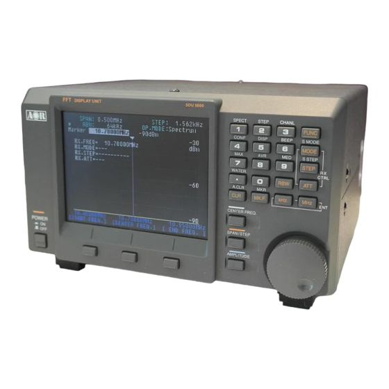
2-1 Front panel controls The front panel of the SDU5600 is dominated by the large color LCD. Controls are ‘grouped’ to assist efficient operation; there are a total of 26 keys in addition to the power on/off switch and the rotary dial encoder. - Page 6 LCD (Liquid Crystal Display) 5 inch TFT color display graphics Special function keys Three special function keys are located under the LCD. There is no ‘printed legend’ identifying the keys as their operations are defined by which menu is active on the LCD.
-
Page 7: Rear Panel
6. Special keys Three (3) special keys are provided with the SDU5600. Those keys are to be used for entry of center frequency, frequency span/step, and amplifier gain select. 2-2 Rear panel The rear of the SDU5600 has two (2) DB-9 connectors for connection to the companion receiver and PC, one (1) BNC connector for IF input, and one (1) DC power connector. -
Page 8: Connection To A Receiver
3 Connection to a receiver 3-1 Configuration of the AR5000 receiver Before connecting the SDU5600 to a receiver, the power switch of the SDU5600 and the receiver must be turned off. In order to control the AR5000 receiver, the following setting is required to the AR5000 receiver. -
Page 9: Switch On The Sdu5600
SDU5600 so that the display appears on the receiver and the SDU5600. Please note that the AR5000 must be set to 9600 bps in advance. To switch off the SDU5600, press the power switch again and then switch off the AR5000. 5 Operations of the SDU5600... - Page 10 (10 MHz / 320 steps on the X – axis = 31.250 KHz) In the Step Resolution Mode, each step will be will be equal to the frequency step. (7) OP. MODE Operating Mode Three operating modes are available with the SDU5600. • Spectrum : Spectrum Analyzer mode •...
-
Page 11: Main Control Keys
To delete all entry, press the CLR key while holding the FUNC key. 5-3 Default Mode Pressing the CLR key repeatedly, will cause the SDU5600 to be set to the default mode with the following settings: Marker Mode:... -
Page 12: When The Communication Is Disconnected From The Receiver
To enter the Configuration Menu, press the FUNC key and press the [4] key. Then the following screen appears. [RX] key : To select the receiver connected with the SDU5600, press the [RX] key that is defined as the left of the Special function keys. The [RX] icon will be displayed in reverse waiting for selection of the receiver. -
Page 13: Companion Receivers
This is to perform settings for the companion receiver. (Note: This setting will not be available if the connected receiver is selected as Other (10M) or Other (45M). Also, if the communication between the SDU5600 and the receiver is not properly established, this setting will not work.) -
Page 14: Controlling The Receive Frequency
When the AR5000 receiver is set to the AUTO receive mode, the AR5000 will automatically select the proper receive mode and the IF filter according to the receive frequency. Under this setting, the IF filter cannot be selected by the SDU5600. 6-4 Controlling the receive frequency... -
Page 15: Channel Scope Mode
Special function keys. In this case, the receive frequency will change according to the step displayed on the top right of the screen of the SDU5600. (Note: The center frequency cannot be changed if Other (10M) or Other (45M) are selected.) -
Page 16: Operation Modes
(regular) marker. 6-5 Operation Modes There are three (3) operation modes with your SDU5600. They are the Spectrum Analyzer Mode, Step Resolution Mode, and the Channel Scope Mode. To go to the Spectrum Analyzer Mode, press the [FUNC] key and press the [1] key on the Main Control Keys. - Page 17 The followings are the features of respective mode. • Spectrum Analyzer Mode (SPECT) The standard default mode used by the SDU5600 is spectrum analyzer mode “SPECT”. • Step Resolution Mode (StepReso) In the Step Resolution Mode, ONLY the wanted frequency steps are checked for activity rather than the entire band.
-
Page 18: Basic Settings For Operation
6-6 Basic Settings for Operation 6-6-1 Spectrum Analyzer Mode On the above screen, the following information is displayed. Center frequency (CF): 122.5 MHz Frequency span: 10.0 MHz Start frequency: 117.5 MHz End (Stop) frequency: 127.5 MHz Marker frequency: 123.5 MHz Display step: 31.25 KHz Center Frequency (CF) -
Page 19: Step Resolution Mode
Press the [SPAN/STEP] key located between the LCD display and the rotary dial encoder. The icon indicating the current span frequency will be reversed prompting the entry of new span frequency. Using the numeric keypad, enter a new frequency span. Start Frequency, End (Stop) Frequency Enter the Start Frequency and the End (Stop) Frequency using the Special Function Keys located on the lower side of the LCD display and the numeric keys followed by... - Page 20 Center frequency (CF): 122.5 MHz Display step: 25 KHz Frequency span: 8 MHz Start frequency: 118.5 MHz End (Stop) frequency: 126.5 MHz Marker frequency: 124.35 MHz Center Frequency (CF) Press the [CENTER FREQ.] key located between the LCD display and the rotary dial encoder.
-
Page 21: Channel Scope Mode
Enter the Start Frequency and the End (Stop) Frequency using the Special Function Keys located on the lower side of the LCD display and the numeric keys followed by the [ENT] key ([KHz] key or [MHz] key.) [Memo: Displayed frequency range: Spectrum Analyzer Mode --- CF (Center Frequency) +/- (Frequency span/2) Step Resolution Mode --- CF (Center Frequency) +/- (Display step x 160) The Frequency span on the above example: 25 KHz x 320 steps = 8 MHz) -
Page 22: Other Settings
Using the numeric keypad, enter a new frequency followed by the [ENT] key ([KHz] key or [MHz] key.) Step Frequency (Ch. STEP) Press the [Ch. STEP] key using the center Special Function Keys. The icon indicating the step frequency will be reversed prompting the entry of new step frequency. Using the numeric keypad, enter a new step frequency followed by the [ENT] key ([KHz] key or [MHz] key.) End (Stop) Frequency... - Page 23 [Improper setting] On the above screen, the reference level has been set to -30 dBm. In this situation, the internal amplifier of the SDU5600 is saturated, causing the display of noise that does not actually exist. On the above screen, the reference level has been set to -20 dBm. As you can see, a clearer display is observed.
- Page 24 Resolution Band Width (RBW) The resolution is selectable from 4 KHz, 32 KHz, 64 KHz, and 128 KHz. Greater detail is obtained by 4 KHz, often with a lower baseline, while 128 KHz provides faster refresh rates. Press the [RBW] key on the numeric keys. The icon indicating the current Resolution Band Width will be reversed prompting a new entry.
-
Page 25: Marker Function
6-7 Marker Function Selection of Marker / Peak / Continuous Peak is available with your SDU5600. To select the marker function, press the [FUNC] key and press the [MK.F] key on the numeric keypad. - Page 26 • Marker In the normal spectrum analyzer mode, the rotary dial encoder may be used to move the marker position indicated by a vertical bar with triangle symbol. The frequency and strength of traces may be read in this manner. •...
- Page 27 • Continuous Peak (C-Peak) When the Continuous Peak function is activated, the marker automatically hops to the largest new signal once a sweep has completed, and the frequency of transmission is displayed to the right of the “C-Peak” icon. To activate the Continuous Peak function, press the [C-Peak] key on the Special Function Keys.
-
Page 28: Calculation Function
In the Channel Scope mode, the receiver connected to the SDU5600 receives the signal on the marker frequency. This will not affect the start frequency, end (stop) frequency, frequency channel step settings of the SDU5600. -
Page 29: Middle Trace (Med)
Press the [CLR] key to exit from this function. 6-9 Waterfall Function Your SDU5600 has a built-in Waterfall Function. The Waterfall Function allows the display of incoming signals by a time frame. The signals are painted with a color according to their levels. -
Page 30: Display Setting
Press the [FUNC] key and press the [6] key will toggle between the beep sound on and off. 6-12 Resetting the SDU5600 If you wish the SDU5600 to return to the factory default settings, perform the following steps: 1. Turn the SDU5600 power off. -
Page 31: Using The Sdu5600 With The Ar5000 Receiver
7-1 Using the SDU5600 with the AR5000 receiver After turning on the power to the SDU5600, an opening message will be displayed. You will need to select the receiver that is used with the SDU5600. To select the receiver, enter the configuration menu by the following steps: Press the [FUNC] key and press the [4] key. -
Page 32: Monitoring Fm Broadcast Frequencies In The Spectrum Analyzer Mode
( Note: The following functions of the AR5000 can be controlled from the SDU5600. Receive Frequency Receive Mode Frequency Step RF Attenuator on/off No other functions can be controlled by the AR5000.) 7-2 Monitoring FM broadcast frequencies in the Spectrum Analyzer Mode The following screen is a sample display of monitored FM broadcast signals in Japan. -
Page 33: Monitoring Fm Broadcast Frequencies In The Step Resolution Mode
Changing the Resolution Band Width (RBW) (from 4 KHz 128 KHz) • Press the [RBW] key on the numeric keypad. • Rotate the Rotary Dial Encoder to select [128 KHz]. • Press the [ENT] key. • As FM broadcast signals are in the Wide FM mode, it is proper to set the RBW to 128 KHz. -
Page 34: Monitoring Vhf Air Band In The Channel Scope Mode
7-4 Monitoring VHF Air Band in the Channel Scope Mode Let’s try to monitor VHF Air Band in the Channel Scope Mode. • To go into the Channel Scope Mode, press the [FUNC] key and press the [ 3 ] key from the numeric keypad. -
Page 35: Operation Mode Summary
7-5 Operation Mode Summary The following is a summary of the operation mode of the SDU5600. A proper mode should be selected according to your applications. Mode Features Spectrum Analyzer Mode Default operation mode. Best for generic measurements. Required settings: Center Frequency, Span... -
Page 36: Computer Control Information
RF gain is set to a maximum. Under such circumstances, when a strong signal is received, the AGC reacts to reduce the input level to the SDU5600. Some receivers have an AGC OFF position which can prevent such fluctuation. This will, however, consequently increase the distortion / noise in audio when a strong signal is received. -
Page 37: Specifications
AOR USA, Inc. (AOR) warrants its products as described below: AOR will repair or exchange equipment as a result of defects in parts or workmanship for a period of one year from the date of original retail purchase from an authorized AOR dealer. - Page 38 AOR at (310) 787-8615 during normal business hours (9 am ~ 5 pm Pacific Time Zone), or write to AOR USA, INC., 20655 S. Western Ave., Suite 112, Torrance, CA 90501. You may also send a fax to AOR at (310) 787-8619. Additional information is available at the AOR web site: www.aorusa.com...
- Page 39 AOR, LTD. 2-6-4, Misuji, Taitok-Ku Tokyo, 111-0055, Japan http://www.aorja.com AOR USA, INC. 20655 S. Western Ave. Suite 112 Torrance, CA 90501, U.S.A. Phone: 310-787-8615 Fax: 310-787-8619 http://www.aorusa.com info@aorusa.com Copyright © 2003 All rights reserved Downloaded by Amateur Radio Directory www.hamdirectory.info...