Table of Contents
Advertisement
Advertisement
Table of Contents

Related Manuals for Samson C.valve C Class


Summary of Contents for Samson C.valve C Class
- Page 1 TUBE MICROPHONE/INSTRUMENT PREAMPLIFIER WITH DIGITAL OUTPUT...
-
Page 2: Safety Instructions
Safety Instructions Caution: To reduce the hazard of electrical shock, do not remove cover or back. No user serviceable parts inside. Please refer all servicing to qualified personnel. WARNING: To reduce the risk of fire or electric shock, do not expose this unit to rain or moisture. The lightning flash with an arrowhead symbol within an equilateral triangle, is intended to alert the user to the presence of uninsulated "dangerous voltage"... -
Page 3: Table Of Contents
System Set-ups Stacking and Tilting the C valve C valve Connections C•Class Dual Rack Adapter (optional) Block Diagram Specifications Copyright 2003, Samson Technologies Corp. Printed October, 2003 Samson Technologies Corp. 575 Underhill Blvd. P.O. Box 9031 Syosset, NY 11791-9031 Phone: 1-800-3-SAMSON (1-800-372-6766) Fax: 516-364-3888 www.samsontech.com... -
Page 4: Introduction
Samson products in the future. With proper care and adequate air circulation, your C valve will operate trouble free for many years. -
Page 5: C Valve Features
Balanced XLR microphone input and 1/4-inch balanced line input connectors allow easy hook up of mics or instruments. • Oversized, rubber bumpers with tilting feet allow several Samson C class units to be stacked and tilted in an ergonomically correct operating position. •... -
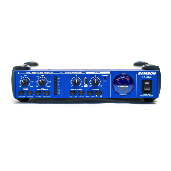
Page 6: Controls And Functions
C valve Layout Front Panel Layout INPUT GAIN – Rotary control used to adjust the input level. LOW FREQUENCY – This rotary control is used to set the EQ cut off point for the Low Cut filter. INPUT METER – Six segment LED VU meter dis- plays the input level after being affected by the Gain control. -
Page 7: Rear Panel Layout
Rear Panel Layout AC INLET – Connect the included AC1800 power supply here. 24 BIT 48 / 96 (DIGITAL OUT)- 24-bit S/PDIF Digital Output on an RCA connector. DIGITAL LINK IN- 1/4-inch input jack for con- necting the balanced line output of a second C valve so that the two units work as a stereo unit transmitting the left and right signals from a sin- gle S/PDIF digital output. -
Page 8: Operating The C Valve
Operating The C valve Setting up the C valve Setting up your C Valve tube pre-amp is a simple procedure, which takes only a few minutes: 1. Remove all packing materials (save them in case of need for future service) and decide where the pre-amp is to be physically placed. -
Page 9: Setting Up The C Valve
Operating The C valve Setting Up the C valve (continued) 6. Plug the C valve power pack into a wall outlet and switch the unit on by pressing the power switch. 7. If you are using an instrument with your C valve, press the MIC/INST switch in to set the C valve’s input to accept instrument levels. -
Page 10: Setting A Good Level
Operating The C valve Setting a Good Level One of the most important fundamentals of good audio engineering is setting proper levels. Even on a small typi- cal mixer, or basic multi-track recorder, there are several controls that affect the level of a signal as it makes it’s way from your sound source to your speakers and then, ultimately, the level of your headphone or monitor sys- tem. -
Page 11: Using The C Valve For Getting A Sound
Operating The C valve MIC/INST - Select switch The MIC/INST switch is used to set the operating level of the C valve’s input. When using a microphone, set the switch to the “MIC” position, which is selected when the switch is in the out position and the green LED is off. -
Page 12: Using The Low Cut Filter
Operating The C valve Using the Low Cut Filter ( continued) LOW FREQUENCY You can set the exact frequency to start attenuating the low-end using the LOW FREQUENCY control knob. Be sure that the LOW CUT filter switch is engaged as described in the previous section. -
Page 13: Using C Valve With An External Signal Processor
RETURN jack located on the C valve’s rear panel. The diagram below shows a typical application for using a compressor (in this example a Samson C com opti) in the C valve’s insertion point. -
Page 14: Using The Digital Output
Operating The C valve Using the Digital Output If you are using a digital recorder that has an S/PDIF digital input, you can take advantage of the C valve’s high quality 24-bit A-to-D converter to make a direct digital connection. Use a high quality co-ax digital cable to connect the C valves RCA S/PDIF output to the S/PDIF. -
Page 15: Using The Digital Link Jack
Operating The C valve Using the DIGITAL LINK Jack For stereo applications, you can connect two C valves together by using the DIGITAL LINK jack. The DIGITAL LINK jack is a 1/4-inch TRS (TIP, RING, SLEEVE) connector providing a balanced input that is connected directly to the C valve right channel input of the A-to-D converter. -
Page 16: System Set-Ups
C valve’s output is connected to the input of a standard PA mixer using a stan- dard 1/4-inch TRS (TIP-RING-SLEEVE) cable. The mixers main left and right outputs are connected to powered PA speakers (for example, the Samson dB500a). Using C Valve to Warm-up a signal You can use the C valve to “warm-up”... -
Page 17: System Set-Ups
C valve System Set-Ups C Valve Stereo Digital Recording Set-up with External Compression... -
Page 18: Stacking And Tilting The C Valve
Stacking and Tilting the C valve Stacking the C valve You can stack one C valve, or any other Samson C Class units, on top of each other by simply lining up the bumpers. Important Note: When stacking the C valve, be sure that only the bottom unit has the tilting feet installed. -
Page 19: C Valve Connections
CONNECTING THE C valve The are several ways to interface the C valve to support a variety of applications. The C valve features servo- balanced inputs and outputs, so connecting balanced and unbalanced signals is possible without any signal loss. The C valve can be used on a single instrument by connecting to a channel’s insert points, or on an entire mix "in-line"... -
Page 20: C•Class Dual Rack Adapter (Optional)
C•Class Dual Rack Adapter (optional) The C Class Dual Rack Adapter is available as an accessory from an authorized Samson dealer. Disconnect any cables, that may be connected, from the C•Class unit to be mounted, i.e., the power supply cable, audio cables, headphones. -
Page 21: Block Diagram
C valve Block Diagram... -
Page 22: Specifications
Specifications System Specifications Frequency Response Dynamic range Crosstalk Detector Inst/Line In Connectors Impedance Max. Input Level Mic Input Connectors Impedance Max. Input Level CMRR Analog Output Connectors Impedance Max. Output Level Digital Output Connector Type Converter Sampling Rate Insert Send Connector Impedance Max. - Page 24 Samson Technologies Corp. 575 Underhill Blvd. P.O. Box 9031 Syosset, NY 11791-9031 Phone: 1-800-3-SAMSON (1-800-372-6766) Fax: 516-364-3888 www.samsontech.com...