Advertisement
Table of Contents
- 1 Owners Manual
- 2 Table of Contents
- 3 Introduction
- 4 MDR6 Features
- 5 Front and Rear Panel Layout
- 6 Controls and Functions
- 7 Front and Rear Panel Layout
- 8 Mono Input Channel Section
- 9 Mastersection
- 10 MDR6 Input and Output Connections
- 11 Operating the MDR6
- 12 Operating the MDR6
- 13 System Set-Ups
- 14 MDR6 Wiring Guide
- 15 Specifications
- 16 Block Diagram
- Download this manual
See also:
Owner's Manual
MIC/LINE 1
MIC/LINE 2
MIC/LINE 3/4
30
30
3/L
5/L
LINE IN
GAIN
GAIN
CLIP
CLIP
4/R
6/R
5
60
5
60
-26
+26
-26
+26
0
0
0
HF
HF
HF
5
5
5
5
5
5
12K
12K
12K
10
10
10
10
10
10
10
15
15
15
15
15
15
0
0
0
MF
MF
MF
5
5
5
5
5
5
2.5K
2.5K
2.5K
10
10
10
10
10
10
10
15
15
15
15
15
15
0
0
0
0
0
0
LF
LF
LF
5
5
5
5
5
5
80Hz
80Hz
80Hz
10
10
10
10
10
10
10
15
15
15
15
15
15
AUX
AUX
AUX
0
10
0
10
0
10
0
0
0
0
0
0
PAN
PAN
BAL
L
R
L
R
L
R
REC
REC
REC
10
10
10
10
10
10
5
5
5
5
5
5
_ _
_ _
_ _
_ _
_ _
_ _
_ _
_ _
_ _
_ _
0
_ _
0
0
_ _
0
0
0
5
5
5
5
5
5
10
10
10
10
10
10
15
15
15
15
15
15
20
20
20
20
20
20
30
30
30
30
30
30
40
40
40
40
40
40
CHANNEL 1
CHANNEL 1
CHANNEL 2
CHANNEL 2
CHANNEL 3/4
CHANNEL 3/4
CHANNEL 5/6
CHANNEL 5/6
SIX CHANNEL MIXER
WITH HARD DISK MODE
Owners Manual
MIC/LINE 5/6
MASTER SECTION
LEFT/MONO
LEFT
LEFT
AUX OUT
AUX RET
CR OUT
MIX OUT
RIGHT
RIGHT
RIGHT
MONO OUT
LINE IN
0
HF
5
5
12K
10
M A X I M U M
D Y N A M I C
R A N G E
15
15
0
5
MF
2T IN
2T OUT
5
5
2.5K
10
15
15
LEFT
RIGHT
LEFT
RIGHT
0
MONO
10
0
0
LF
5
5
80Hz
2TK TO RETURN
5
10
48V
POWER
15
15
AUX
0
10
HARD
PEAK
DISK
+6
AUX RETURN
0
10
0
0
5
0
BAL
-6
-20
L
R
0
10
REC
MASTER SECTION
MIX/2T
10
10
10
10
10
5
5
5
5
5
_ _
_ _
_ _
_ _
_ _
_ _
_ _
C/ROOM
_ _
_ _
+PHONES
_ _
0
0
0
_ _
0
_ _
0
5
5
5
5
5
5
0
10
10
10
10
10
10
15
15
15
15
15
20
20
20
20
20
30
30
30
30
30
40
40
40
40
40
PHONES
L
L
MIX
MIX
R
R
®
Advertisement
Table of Contents

Related Manuals for Samson mdr6


Summary of Contents for Samson mdr6
-
Page 1: Owners Manual
MIC/LINE 1 MIC/LINE 2 MIC/LINE 3/4 MIC/LINE 5/6 MASTER SECTION LEFT/MONO LEFT LEFT AUX OUT AUX RET CR OUT MIX OUT RIGHT RIGHT RIGHT MONO OUT LINE IN LINE IN GAIN GAIN CLIP CLIP M A X I M U M D Y N A M I C R A N G E 2T IN... - Page 2 Safety Instructions/Consignes de sécurité/Sicherheitsvorkehrungen/Instrucciones de seguridad WARNING: To reduce the risk of fire or electric shock, do not expose this unit to ATTENTION: Pour éviter tout risque d’électrocution ou d’incendie, ne pas rain or moisture. To reduce the hazard of electrical shock, do not remove cover or exposer cet appareil à...
-
Page 3: Table Of Contents
Introduction MDR6 Features Controls and Functions Front and Rear Panel Layout 4–5 Mono Input Channel Section 6–7 MasterSection 8–9 MDR6 Input and Output Connections 10–11 Operating the MDR6 12–15 System Set-ups 16–17 MDR6 Wiring Guide Specifications Block Diagram Copyright 2001, Samson Technologies Corp. -
Page 4: Introduction
In these pages, you’ll find a detailed description of the features of the MDR6 mixer, as well as a description of its front and rear panels, step-by-step instructions for its setup and use, and full specifications. You’ll also find a war- ranty card enclosed—please don’t forget to fill it out and mail it in so that you can receive online technical support... -
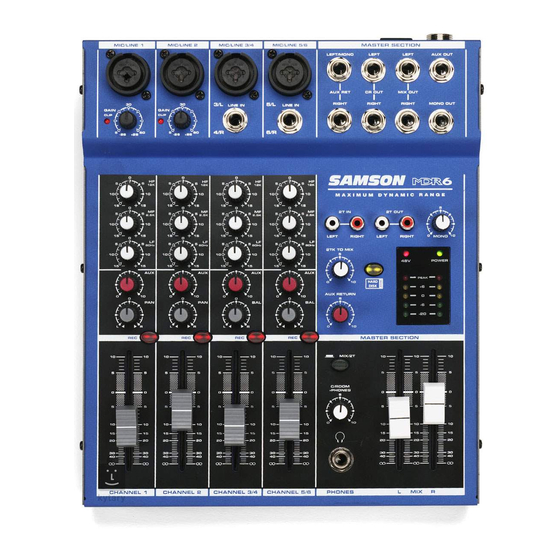
Page 5: Mdr6 Features
CHANNEL 5/6 CHANNEL 5/6 PHONES The Samson MDR6, six channel mixer, is a comprehensive, all-in-one solution for live sound, recording, fixed installation and post production applications. Here are some of its main features: • Six channels – Two Mic/Line plus two Stereo inputs with mic pre’s. -
Page 6: Controls And Functions
M A X I M U M D Y N A M I C R A N G E POWER DESIGNED AND ENGINEERED IN THE UNITED STATES BY SAMSON TECHNOLOGIES CAUTION CAUTION: TO REDUCE THE RISK OF FIRE OR ELECTRIC SHOCK DO NOT REMOVE BOTTOM COVER... -
Page 7: Front And Rear Panel Layout
MID FREQUENCY – Controls the mid band of the Channel Equalizer, +/- 15 dB at 2.5KHz. 22 POWER – Indicates the MDR6 is powered up. LOW FREQUENCY – Controls the low band of the Channel 23 OUTPUT METER - Five segment display with VU Equalizer, +/- 15 dB at 80Hz. -
Page 8: Mono Input Channel Section
The following section details each part of the MDR6’s MONO INPUT CHANNELS including the GAIN control, 3- BAND EQ, AUX send, RECORD, PAN and LEVEL controls. The input channels one through four on the MDR6 feature high quality, discrete transistor pre-amp providing transparency and extended dynamic range. The com- bination connector accepts a standard XLR mic cable for microphone level signals, or a standard 1/4"... - Page 9 PAN (Mono Inputs Only) The MDR6’s PAN control is used to place or position the mono signal into the stereo main Left and Right MIX bus. You can create a stereo image by panning some input signals to the left and others to the right.
-
Page 10: Mastersection
Auxiliary Return The MDR6 has a stereo auxiliary return, which can be accessed via the pair of 1/4-inch phone jacks located on the top panel. The Auxiliary Return can be used to connect any stereo line level signal, but they are primarily used to connect the output of external effects processors. - Page 11 Controls and Functions MASTER SECTION C/ROOM + PHONES The C/ROOM + PHONES control is used to set the level sent to the control room outputs, and also to the headphone jack. M A X I M U M D Y N A M I C R A N G E +48V - Phantom Power LED 2T IN...
-
Page 12: Mdr6 Input And Output Connections
Line Level Input - Stereo Input Channels The MDR6’s stereo channels have a stereo LINE input with the Left Input located in the center of the Combie connector and a separate 1/4-inch connector for the Right Input. You can connect the outputs from stereo devices such as synthesizers, drum machines, effects processors or any stereo line-level sig- nal. - Page 13 MDR6 Input and Output Connections EXTERNAL OUTPUT JACKS The MDR6 features several output connectors allowing you to interface a variety of external devices. A stereo recording device such as a cassette recorder can be connected to the 2 Track jacks, and additional power ampli- fiers can be connected to the CONTROL ROOM and MAIN output jacks.
-
Page 14: Operating The Mdr6
5. Set the Left and Right MIX faders in the MDR6’s master section to the "0" position. 6. While speaking into the mic (or playing the instrument), adjust the channel Fader control so that the "0" LED of the MAIN section peak level meter lights occasionally. - Page 15 PEAK DISK AUX RETURN 2. In order to get the most gain from your monitor mix, use an external graphic equalizer like a Samson E31i to cut out any frequencies that cause feedback. USING AN EXTERNAL EFFECT If you want to use an external device for effects processing, MASTER SECTION you can easily connect the unit using the MDR6 AUX bus.
- Page 16 When you are working with the mixer configured to HDM, the MDR6 engages the RECORD bus and a special 2- Track listening mode. When engaged, the HDM allows you to assign any of the channels to the RECORD bus.
-
Page 17: Operating The Mdr6
Using The HDM (Continued) Overdubbing Using HDM Now that you have recorded a basic rhythm track you can overdub additional tracks using MDR6’s HDM. For this example, we’ll overdub a vocal track using a microphone. Follow the steps below. 1. Connect the output from your computer sound card to the MDR6’s 2-Track In and then connect the MDR6’s 2-Track Output to the input of the sound card. -
Page 18: System Set-Ups
MDR6 System Set-Ups MDR6 LIVE SOUND SET-UP SIGNAL FLOW SIGNAL FLOW MODE SIGNAL FLOW SIGNAL FLOW SIGNAL FLOW SIGNAL FLOW... - Page 19 MDR6 System Set-Ups MDR6 RECORDING SET UP SIGNAL FLOW SIGNAL FLOW SIGNAL FLOW SIGNAL FLOW...
-
Page 20: Mdr6 Wiring Guide
MDR6 Wiring Guide CONNECTING THE MDR6 The are several ways to interface the MDR6 to support a variety of applications. The MDR6 features balanced inputs and outputs, so connecting balanced and unbalanced signals is possible. Unbalanced 1/4” Connector Signal Signal... -
Page 21: Specifications
MDR6 Specifications Frequency Response (Trim @ Min, unity gain ± 3 dB) Mic to Main 5 Hz - 54 kHz Line to Main 5 Hz - 54 kHz Aux Return to Main 5 Hz - 98 kHz Line to Aux Send 5 Hz - 57 kHz T.H.D. -
Page 22: Block Diagram
Block Diagram... - Page 24 Samson Technologies Corp. 575 Underhill Blvd. P.O. Box 9031 Syosset, NY 11791-9031 Phone: 1-800-3-SAMSON (1-800-372-6766) Fax: 516-364-3888 www.samsontech.com...