D-Link DGS-3130-30TS Hardware Installation Manual
Dgs-3130 series layer 3 stackable managed switch
Hide thumbs
Also See for DGS-3130-30TS:
- Web ui reference manual (489 pages) ,
- Quick installation manual (28 pages)
Table of Contents
Advertisement
Advertisement
Table of Contents

Related Manuals for D-Link DGS-3130-30TS


Summary of Contents for D-Link DGS-3130-30TS
- Page 2 Information in this document is subject to change without notice. Reproduction in any manner whatsoever, without the written permission of D-Link Corporation, is strictly forbidden. Trademarks used in this text: D-Link and the D-LINK logo are trademarks of D-Link Corporation; Microsoft and Windows are registered trademarks of Microsoft Corporation.
-
Page 3: Intended Readers
DGS-3130 Series Layer 3 Stackable Managed Switch Hardware Installation Guide Intended Readers The DGS-3130 Series Layer 3 Stackable Managed Switch Hardware Installation Guide contains detailed information about the hardware specifications of the switches in this series. It also contains brief information on how to configure and manage a switch in this series. - Page 4 DGS-3130 Series Layer 3 Stackable Managed Switch Hardware Installation Guide The product has been dropped or damaged. The product does not operate correctly when the operating instructions are correctly followed. General safety cautions: Keep the system away from radiators and heat sources. Also, do not block cooling vents. ...
-
Page 5: General Precautions For Rack-Mountable Products
DGS-3130 Series Layer 3 Stackable Managed Switch Hardware Installation Guide General Precautions for Rack-Mountable Products Please pay careful attention to the following precautions concerning rack stability and safety. Systems are considered to be components in a rack. Thus, a component refers to any system, as well as to various peripherals or supporting hardware: CAUTION: Installing systems in a rack without the front and side stabilizers installed could cause the rack to tip over, potentially resulting in bodily injury under certain circumstances. -
Page 6: Table Of Contents
1. Introduction ................................8 Switch Description ............................... 8 Package Contents ................................ 8 Features ..................................9 2. Hardware Components ............................11 DGS-3130-30TS Switch ............................. 11 Front Panel Components ............................11 LED Indicators ..............................11 Rear Panel Components ............................13 Side Panel Components ............................13 DGS-3130-30S Switch ............................... - Page 7 DGS-3130 Series Layer 3 Stackable Managed Switch Hardware Installation Guide Installing the Redundant Power Supply (RPS) ......................34 DPS-500A Series Redundant Power Supply Unit ....................35 Installing the RPS into a Rack-mount Chassis ......................35 DPS-800 Rack-mount Chassis ..........................35 DPS-700 ................................
-
Page 8: Introduction
Features Switch Description The D-Link DGS-3130 Series is a high performance member of the D-Link Lite Layer 3 switch family. Ranging from 10/100/1000 Mbps edge switches to core gigabit switches, the switch family has been future-proof designed to provide fault tolerance, flexibility, port density, robust security, and maximum throughput with a user-friendly management interface for the networking professional. -
Page 9: Features
The list below highlights the significant protocols and features supported by this switch. Features that can be found on this switch are: Virtual Stacking. D-Link Single IP Management Queue Handling: Strict Priority Queue (SPQ), (SIM) Weighted Round Robin (WRR), and Weight ... - Page 10 802.1ag Connectivity Fault Management (CFM) Y.1731 OAM Optical Transceiver Digital Diagnostic Monitoring (DDM) D-Link Unidirectional Link Detection (DULD) Network Time Protocol (NTP) IPv4/IPv6 Simple Network Time Protocol (SNTP) IPv4/IPv6 Link Layer Discovery Protocol (LLDP), and LLDP-MED ...
-
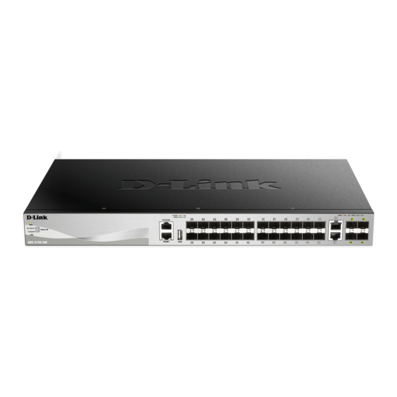
Page 11: Hardware Components
DGS-3130-30TS Switch Front Panel Components The front panel of DGS-3130-30TS features a variety of LED indicators and ports. Figure 2-1 Front panel view of the DGS-3130-30TS Ports that can be found on the front panel of this switch are listed in the table below. - Page 12 DGS-3130 Series Layer 3 Stackable Managed Switch Hardware Installation Guide Figure 2-2 LED indicators for the DGS-3130-30TS Description Power This LED will light solid green after the Switch has been powered on successfully. This LED will be off when the Switch is no longer receiving power (i.e. powered off).
-
Page 13: Rear Panel Components
The rear panel of this switch features a security lock, a GND, an AC power connector, a power cord retainer hole, and an outlet for an external redundant power supply. Figure 2-3 Rear panel view of the DGS-3130-30TS Components that can be found on the rear panel of this switch are listed in the table below. -
Page 14: Dgs-3130-30S Switch
DGS-3130 Series Layer 3 Stackable Managed Switch Hardware Installation Guide Figure 2-4 Side panels of the DGS-3130-30TS DGS-3130-30S Switch Front Panel Components The front panel of DGS-3130-30S features a variety of LED indicators and ports. Figure 2-5 Front panel view of the DGS-3130-30S Ports that can be found on the front panel of this switch are listed in the table below. - Page 15 DGS-3130 Series Layer 3 Stackable Managed Switch Hardware Installation Guide Figure 2-6 LED indicators for the DGS-3130-30S Description Power This LED will light solid green after the Switch has been powered on successfully. This LED will be off when the Switch is no longer receiving power (i.e. powered off).
-
Page 16: Rear Panel Components
DGS-3130 Series Layer 3 Stackable Managed Switch Hardware Installation Guide Description when a 10 Gbps port is active or blink amber when a 1 Gbps port is active. The LED will be off when there is no link or activity. Stack ID This 7-segment LED can display numbers from 1 to 9 and the following letters H, h, E, and G. -
Page 17: Dgs-3130-30Ps Switch
DGS-3130 Series Layer 3 Stackable Managed Switch Hardware Installation Guide Figure 2-8 Side panels of the DGS-3130-30S DGS-3130-30PS Switch Front Panel Components The front panel of DGS-3130-30PS features a variety of LED indicators and ports. Figure 2-9 Front panel view of the DGS-3130-30PS Ports that can be found on the front panel of this switch are listed in the table below. - Page 18 DGS-3130 Series Layer 3 Stackable Managed Switch Hardware Installation Guide Figure 2-10 LED indicators for the DGS-3130-30PS Description Power This LED will light solid green after the Switch has been powered on successfully. This LED will be off when the Switch is no longer receiving power (i.e. powered off).
-
Page 19: Rear Panel Components
DGS-3130 Series Layer 3 Stackable Managed Switch Hardware Installation Guide Description The LED at the right side indicates the status of PoE. When this light is on with a solid green light, it means that the corresponding ports are feeding power to the PoE devices plugged in. -
Page 20: Side Panel Components
DGS-3130 Series Layer 3 Stackable Managed Switch Hardware Installation Guide Side Panel Components The side panels of this switch contain heat vents, fans, and rack-mounting screw holes. The heat vents are used to dissipate internal heat and facilitate internal air circulation. Do not block these openings. Leave at least 4 inches of space at the sides of the Switch for proper ventilation. - Page 21 DGS-3130 Series Layer 3 Stackable Managed Switch Hardware Installation Guide Figure 2-14 LED indicators for the DGS-3130-54TS Description Power This LED will light solid green after the Switch has been powered on successfully. This LED will be off when the Switch is no longer receiving power (i.e. powered off).
-
Page 22: Rear Panel Components
DGS-3130 Series Layer 3 Stackable Managed Switch Hardware Installation Guide Description The letter ‘H’ will be displayed if this switch is the master switch in the stack. The letter ‘h’ will be displayed if this switch is the backup master switch in the stack. -
Page 23: Side Panel Components
DGS-3130 Series Layer 3 Stackable Managed Switch Hardware Installation Guide Side Panel Components The side panels of this switch contain heat vents, fans, and rack-mounting screw holes. The heat vents are used to dissipate internal heat and facilitate internal air circulation. Do not block these openings. Leave at least 4 inches of space at the sides of the Switch for proper ventilation. - Page 24 DGS-3130 Series Layer 3 Stackable Managed Switch Hardware Installation Guide Figure 2-18 LED indicators for the DGS-3130-54S Description Power This LED will light solid green after the Switch has been powered on successfully. This LED will be off when the Switch is no longer receiving power (i.e. powered off).
-
Page 25: Rear Panel Components
DGS-3130 Series Layer 3 Stackable Managed Switch Hardware Installation Guide Description when a 10 Gbps port is active or blink amber when a 1 Gbps port is active. The LED will be off when there is no link or activity. Stack ID This 7-segment LED can display numbers from 1 to 9 and the following letters H, h, E, and G. -
Page 26: Side Panel Components
DGS-3130 Series Layer 3 Stackable Managed Switch Hardware Installation Guide Side Panel Components The side panels of this switch contain heat vents, fans, and rack-mounting screw holes. The heat vents are used to dissipate internal heat and facilitate internal air circulation. Do not block these openings. Leave at least 4 inches of space at the sides of the Switch for proper ventilation. - Page 27 DGS-3130 Series Layer 3 Stackable Managed Switch Hardware Installation Guide Figure 2-22 LED indicators for the DGS-3130-54PS Description Power This LED will light solid green after the Switch has been powered on successfully. This LED will be off when the Switch is no longer receiving power (i.e. powered off).
-
Page 28: Rear Panel Components
DGS-3130 Series Layer 3 Stackable Managed Switch Hardware Installation Guide Description that the port is in an error condition state. When this light is off, it means that the ports are not supplying power to the devices plugged into the ports. Stack ID This 7-segment LED can display numbers from 1 to 9 and the following letters H, h, E, and G. -
Page 29: Side Panel Components
DGS-3130 Series Layer 3 Stackable Managed Switch Hardware Installation Guide Component Description speed. This port can be used to configure the Switch without being connected to the network. Console (RJ45) The RJ45 console port can be used to connect to the Command Line Interface (CLI) of the Switch for configuration, management, and monitoring. -
Page 30: Installation
DGS-3130 Series Layer 3 Stackable Managed Switch Hardware Installation Guide 3. Installation Installation Guidelines Installing the Switch without a Rack Installing the Switch in a Standard 19" Rack Installing Transceivers into the Transceiver Ports Power On (AC Power) Installing the Redundant Power Supply (RPS) Installing the RPS into a Rack-mount Chassis Installation Guidelines This section will discuss the hardware installation guidelines that the user must follow in order to properly and safely... -
Page 31: Installing The Switch In A Standard 19" Rack
DGS-3130 Series Layer 3 Stackable Managed Switch Hardware Installation Guide Installing the Switch in a Standard 19" Rack This section is used to guide the user through installing the Switch into a switch rack. The Switch can be mounted in a standard 19"(1U) rack using the provided mounting brackets. -
Page 32: Power On (Ac Power)
DGS-3130 Series Layer 3 Stackable Managed Switch Hardware Installation Guide Figure 3-4 Inserting transceivers into the transceiver ports The SFP+ ports also support other transceiver form factors like SFP and SFP+ transceivers. A complete list of SFP/SFP+ transceivers, compatible with this switch, can be found the SFP Ports and SFP+ Ports sections in Appendix A - Technical Specifications at the end of this document. - Page 33 DGS-3130 Series Layer 3 Stackable Managed Switch Hardware Installation Guide Figure 3-5 Insert Tie Wrap into the Switch 2. Plug the AC power cord into the power socket of the Switch. Figure 3-6 Connect the power cord to the Switch 3.
-
Page 34: Installing The Redundant Power Supply (Rps)
Installing the Redundant Power Supply (RPS) The Redundant Power Supply (RPS) is designed to conform to the wattage requirements of D-Link’s Ethernet and Gigabit switches. It is an external RPS unit enclosed in solid metal case with sockets to connect AC or DC power sources on one end, and to connect to a switch’s internal power supply on the other end. -
Page 35: Dps-500A Series Redundant Power Supply Unit
DGS-3130 Series Layer 3 Stackable Managed Switch Hardware Installation Guide DPS-500A Series Redundant Power Supply Unit This RPS (DPS-500A) can be connected to the Switch’s RPS port using a 14-pin DC power cable. A standard, three- pronged AC power cable connects the RPS to the main power source. Figure 3–10 Connecting a DGS-3130 Series Switch to the DPS-500A Remove the AC power cord from the AC power port of the Switch. -
Page 36: Dps-700
DGS-3130 Series Layer 3 Stackable Managed Switch Hardware Installation Guide Figure 3–11 Install the DPS-500A in the DPS-800 The DPS-800 can be mounted into a standard 19" rack, as shown below. Figure 3–12 Install the DPS-800 in an Equipment Rack DPS-700 The DPS-700 is connected to the Master Switch using a 22-pin DC power cable. - Page 37 DGS-3130 Series Layer 3 Stackable Managed Switch Hardware Installation Guide Figure 3–13 Front view of the DPS-700 1. Insert one end of the 22-pin DC power cable into the receptacle on the Switch and the other end into the Redundant Power Supply unit. 2.
-
Page 38: Switch Connections
DGS-3130 Series Layer 3 Stackable Managed Switch Hardware Installation Guide 4. Switch Connections Switch to an End Node Switch to Another Switch Switch Stacking Switch to a Server Switch to an End Node An end node is a generic name for edge networking devices that will be connected to this switch. Typical examples of end nodes are Personal Computers (PCs), Notebooks, Access Points, Print Servers, VoIP Phones and more. -
Page 39: Switch Stacking
DGS-3130-30TS/30S/30PS model consumes one stacking cost and DGS-3130-54TS/54S/54PS consumes two stacking costs in a stack. Therefore, if the stack is constructed of DGS-3130-30TS/30S/30PS series, the maximum stacking number is 9 devices per stack. If the stack is constructed of DGS-3130-54TS/54S/54PS series, the maximum stacking number is 6 devices per stack due to stacking cost of DGS-3130- 54TS/54S/54PS is two. - Page 40 DGS-3130 Series Layer 3 Stackable Managed Switch Hardware Installation Guide The figure below illustrates how switches can be stacked in a Duplex Chain formation using RJ45 cables, optical fiber cables connected to SFP+ transceivers or DAC with SFP+ connectors where the 2-port or 4-port stacking configuration is used.
- Page 41 DGS-3130 Series Layer 3 Stackable Managed Switch Hardware Installation Guide Figure 4-4 2-Port Duplex Chain stacking topology (SFP+ ports)
- Page 42 DGS-3130 Series Layer 3 Stackable Managed Switch Hardware Installation Guide Figure 4-5 4-Port Duplex Chain stacking topology (10GBase-T and SFP+ ports)
- Page 43 DGS-3130 Series Layer 3 Stackable Managed Switch Hardware Installation Guide Figure 4-6 4-Port Duplex Chain stacking topology (SFP+ ports)
- Page 44 DGS-3130 Series Layer 3 Stackable Managed Switch Hardware Installation Guide The figure below illustrates how switches can be stacked in a Duplex Ring formation using RJ45 cables, optical fiber cables connected to SFP+ transceivers or DAC with SFP+ connectors where the 2-port or 4-port stacking configuration is used.
- Page 45 DGS-3130 Series Layer 3 Stackable Managed Switch Hardware Installation Guide Figure 4-8 2-port Duplex Ring stacking topology (SFP+ ports)
- Page 46 DGS-3130 Series Layer 3 Stackable Managed Switch Hardware Installation Guide Figure 4-9 4-port Duplex Ring stacking topology (10GBase-T and SFP+ ports)
- Page 47 DGS-3130 Series Layer 3 Stackable Managed Switch Hardware Installation Guide Figure 4-10 4-port Duplex Ring stacking topology (SFP+ ports) NOTE: When 4-port duplex ring with 10GBase-T and SFP+ port topology is used and odd number switches are in one stack, one of the switch in stack should be set as 4-port-SFP+ mode.
-
Page 48: Switch To A Server
DGS-3130 Series Layer 3 Stackable Managed Switch Hardware Installation Guide Switch to a Server The Switch is ideal for connecting to a network backbone, server, or server farm. The RJ45 ports operate at a speed of 10/100/1000 Mbps. The SFP ports operate at a speed of 100/1000 Mbps. The SFP+ ports operate at a speed of 1/10 Gbps. -
Page 49: Switch Management
DGS-3130 Series Layer 3 Stackable Managed Switch Hardware Installation Guide 5. Switch Management Management Options Connecting to the Console Port Connecting to the MGMT Port Connecting using SNMP Management Options This switch provides multiple access platforms that can be used to configure, manage, and monitor networking features available on this switch. - Page 50 DGS-3130 Series Layer 3 Stackable Managed Switch Hardware Installation Guide To configure the terminal emulation software as follows: Select the appropriate serial port (COM1 or COM2). Set the data rate to 115200 baud. Set the data format to 8 data bits, 1 stop bit, and no parity. ...
-
Page 51: Connecting To The Switch For The First Time
DGS-3130-30TS Gigabit Ethernet Switch Command Line Interface Firmware: Build 1.00.001 Copyright(C) 2017 D-Link Corporation. All rights reserved. Switch> By default, there is no Username and Password configured in the account settings of this switch. This will allow the user to simply connect to this Switch for the first time by pressing the ‘Enter’ key. After pressing Enter, access will be given to enter commands after the command prompt (Switch>) appears. -
Page 52: Configuring The Ip Address
DGS-3130 Series Layer 3 Stackable Managed Switch Hardware Installation Guide NOTE: Passwords are case sensitive. Usernames can be up to 32 characters in length. Passwords can be up to 32 plain-text characters in length. Configuring the IP Address Each switch must be assigned its own in-band IP Address, which is used for communication with an SNMP network manager or other TCP/IP applications. -
Page 53: Connecting Using Snmp
DGS-3130 Series Layer 3 Stackable Managed Switch Hardware Installation Guide Connecting using SNMP The Simple Network Management Protocol (SNMP) is an OSI Layer 7 (Application Layer) protocol designed specifically for managing and monitoring network devices. SNMP enables network management stations to read and modify the settings of gateways, routers, switches, and other network devices. -
Page 54: Web-Based Switch Configuration
DGS-3130 Series Layer 3 Stackable Managed Switch Hardware Installation Guide 6. Web-based Switch Configuration Introduction Logging into the Web UI Web User Interface (Web UI) Introduction Most software functions of the Switch can be managed, configured, and monitored via the embedded HTML Web UI. Management can be done on the Switch from remote stations anywhere on the network through a standard web browser. -
Page 55: Web User Interface (Web Ui)
Switch. This area displays the Switch’s ports and expansion modules. It also shows port activity based on a specific mode. Some management functions, including port monitoring, are accessible from here. Click the D-Link logo to go to the D-Link website. -
Page 56: Web Pages
Features regarding the Switch’s Operations, Administration and Maintenance (OAM) can be viewed and configured in this folder. The Switch’s configuration and statistics can be viewed and configured in Monitoring this folder. Green Features regarding the D-Link Green Technology can be viewed and configured in this folder. -
Page 57: Appendix A - Technical Specifications
Supports a USB 2.0 Type-A flash drive with a maximum current of 1 A. This slot only supports FAT16 and FAT32 file system architectures Power Consumption DGS-3130-30TS: 30.76W (Max.), 23.20W (Standby) DGS-3130-30S: 82.4W (Max.), 43.9W (Standby) DGS-3130-30PS: 471.67W (Max.), 52.44W (Standby) DGS-3130-54TS: 50.62W (Max.), 38.67W (Standby) -
Page 58: Performance
DGS-3130-54S: 446.99 BTU/Hr. (Max.) DGS-3130-54PS: 1662.6 BTU/Hr. (Max.) Dimensions DGS-3130-30TS: 440 mm (W) x 250 mm (D) x 44 mm (H), 19-inch, 1 U Rack-mount size DGS-3130-30S: 440 mm (W) x 250 mm (D) x 44 mm (H), 19-inch, 1 U... -
Page 59: Led Indicators
IP Routing Tables IPv4: Max. 512 entries IPv6: Max. 512 entries Virtual Stacking / Clustering Supports D-Link Single IP Management version 1.61 Manages up to 32 devices in a virtual stack with a single IP address LED Indicators Location Color... - Page 60 DGS-3130 Series Layer 3 Stackable Managed Switch Hardware Installation Guide Location Color Status Description Light on (G) Safeguard Engine in exhausted mode LED Per Link/Act/Speed Green Light on (Solid) When there is a connection (or link) to a 10/100/1000 Mode 1000 Mbps Ethernet device on any of the Mbps Port ports...
-
Page 61: Port Functions
DGS-3130 Series Layer 3 Stackable Managed Switch Hardware Installation Guide Port Functions Feature Description RJ45 Ports Compliant with the following standards: IEEE 802.3 compliance IEEE 802.3u compliance IEEE 802.3ab compliance IEEE 802.3an compliance IEEE 802.3az compliance (Energy Efficient Ethernet) Support Full-Duplex operations ... - Page 62 DGS-3130 Series Layer 3 Stackable Managed Switch Hardware Installation Guide Feature Description DEM-436XT-BXU (10GBASE-LR, single-mode, 20 km, TX: 1270 nm / RX: 1310 nm, without DDM) SFP+ Direct Attached Cables (DAC) Supported: DEM-CB100S (10G SFP+, 1 m) for stacking or uplink connection ...
-
Page 63: Appendix B - Cables And Connectors
DGS-3130 Series Layer 3 Stackable Managed Switch Hardware Installation Guide Appendix B - Cables and Connectors Ethernet Cable When connecting the Switch to another switch, a bridge or hub, a straight-through Cat5/5e/6a/7 cable is necessary. Please review these products for matching cable pin assignment. The following diagrams and tables show the standard RJ45 receptacle/connector and their pin assignments. -
Page 64: Console Cable (Rj45 To Rs-232)
DGS-3130 Series Layer 3 Stackable Managed Switch Hardware Installation Guide Console Cable (RJ45 to RS-232) A console cable is used to connect to the RJ45 console port of the Switch to access the command line interface. The following diagram and table show the standard RJ45 to RS-232 cable and pin assignments. Figure B-2 Console to RJ45 Cable Contact Console (DB9/RS232) -
Page 65: Redundant Power Supply (Rps) Cable
DGS-3130 Series Layer 3 Stackable Managed Switch Hardware Installation Guide Redundant Power Supply (RPS) Cable When connecting the Switch to a Redundant Power Supply, an RPS cable is necessary. Please review this product for matching cable pins. The following diagram and table show the standard RPS connector and its pin assignments. Figure B-3 RPS Cable for DPS-500A (14-pin Power Cable) RPS Cable –... - Page 66 DGS-3130 Series Layer 3 Stackable Managed Switch Hardware Installation Guide Figure B-4 RPS Cable for DPS-700 (22-pin Power Cable) Device DPS-700 -54Vrtn -54Vrtn -54V -54V +12V +12V +12V +12V +12V +12V +12V +12V NC/GND +12Ven +12Ven LS-54V LS-54V -54V -54V -54Vrtn -54Vrtn NC/GND...
-
Page 67: Warranty & Technical Support
The customer must submit with the product as part of the claim a written description of the Hardware defect or Software nonconformance in sufficient detail to allow D-Link to confirm the same, along with proof of purchase of the product (such as a copy of the dated purchase invoice for the product) if the product is not registered. - Page 68 D-Link Corporation/D-Link Systems, Inc., as stipulated by the United States Copyright Act of 1976 and any amendments thereto. Contents are subject to change without prior notice. Copyright 2004 by D-Link Corporation/D-Link Systems, Inc.
- Page 69 Product Registration Register your D-Link product online at http://support.dlink.com/register/ Product registration is entirely voluntary and failure to complete or return this form will not diminish your warranty rights.
- Page 70 This guide is only for initial configuration. Please refer to the user manual to learn more or visit http://www.mydlink.com for more information. Also feel free to contact us. U.S. and Canadian customers can contact D-Link Technical Support through our website. http://support.dlink.com Canada...
- Page 71 Europe customers TECHNICAL SUPPORT TECHNISCHE UNTERSTÜTZUNG ASSISTANCE TECHNIQUE ASISTENCIA TÉCNICA SUPPORTO TECNICO TECHNISCHE ONDERSTEUNING POMOC TECHNICZNA TECHNICKÁ PODPORA TECHNICKÁ PODPORA dlink.com/support TECHNIKAI TÁMOGATÁS TEKNISK SUPPORT TEKNISK SUPPORT TEKNISK STØTTE TEKNINEN TUKI ASSISTÊNCIA TÉCNICA ΤΕΧΝΙΚΉ ΥΠΟΣΤΉΡΙΞΗ TEHNIČKA PODRŠKA TEHNIČNA PODPORA SUPORT TEHNIC ТЕХНИЧЕСКА...
- Page 72 Indonesia - www.dlink.co.id Malaysia - www.dlink.com.my Philippines - www.dlink.com.ph Vietnam - www.dlink.com.vn Korea customers Tel : +82-2-2028-1810 Monday to Friday 9:00am to 6:00pm Web : http://d-link.co.kr E-mail : g2b@d-link.co.kr New Zealand customers Tel: 0800-900-900 24/7 Technical Support Web: http://www.dlink.co.nz E-mail: support@dlink.co.nz...
- Page 73 08600 DLINK (for South Africa only) Monday to Friday 8:30am to 9:00pm South Africa Time Web: http://www.d-link.co.za E-mail: support@za.dlink.com D-Link Middle East - Dubai, U.A.E. customers Plot No. S31102, Jebel Ali Free Zone South, P.O.Box 18224, Dubai, U.A.E. Tel: +971-4-8809022...
- Page 74 Pakistan customers Islamabad Office: 61-A, Jinnah Avenue, Blue Area, Suite # 11, EBC, Saudi Pak Tower, Islamabad - Pakistan Tel.: +92-51-2800397, 2800398 Fax: +92-51-2800399 Karachi Office: D-147/1, KDA Scheme # 1, Opposite Mudassir Park, Karsaz Road, Karachi – Pakistan Phone: +92-21-34548158, 34326649 Fax: +92-21-4375727 Technical Support: +92-21-34548310, 34305069 General Inquiries: info.pk@me.dlink.com...
- Page 75 Обновления программного обеспечения и документация доступны на Интернет-сайте D-Link. D-Link предоставляет бесплатную поддержку для клиентов в течение гарантийного срока. Клиенты могут обратиться в группу технической поддержки D-Link по телефону или через Интернет. Техническая поддержка компании D-Link работает в круглосуточном режиме ежедневно, кроме официальных праздничных дней. Звонок...
- Page 77 Офисы Россия Հայաստան Москва, Графский переулок, 14 Երևան, Դավթաշեն 3-րդ Тел. : +7 (495) 744-00-99 թաղամաս, 23/5 E-mail: mail@dlink.ru Հեռ.՝ +374 (10) 39-86-67 Էլ. փոստ՝ info@dlink.am Україна Київ, вул. Межигірська, 87-А Latvija Тел.: +38 (044) 545-64-40 Rīga, Lielirbes iela 27 E-mail: ua@dlink.ua Tel.: +371 (6) 761-87-03 E-mail: info@dlink.lv...
- Page 78 Soporte Técnico Para Usuarios En Latino America Por favor revise el número telefónico del Call Center de su país en http://www.dlinkla.com/soporte/call-center Soporte Técnico de D-Link a través de Internet Horario de atención Soporte Técnico en www.dlinkla.com e-mail: soporte@dlinkla.com & consultas@dlinkla.com...
- Page 79 Clientes de Brasil Caso tenha dúvidas na instalação do produto, entre em contato com o Suporte Técnico D-Link. Acesse o site: www.dlink.com.br/suporte...
- Page 80 台灣服務時間:週一至週五 : 9:00~21:00 週六日及國定假日 ( 不含農曆春節 ) 10:00~19:00 台灣網站: http://www.dlink.com.tw 台灣電子郵件: dssqa_service@dlink.com.tw 產品保固期限、台灣區維修據點查詢,請參考 http://www.dlink.com.tw 網頁說明。 香港、澳門 D-Link 技術諮詢專線 香港技術諮詢服務專線 (852) 8100 8892 香港服務時間:週一至週五 9:00AM~1:00PM 及 2:00PM~6:00PM 週六 9:00AM~1:00PM 香港網站: http://www.dlink.com.hk 香港電子郵件: service@cn.synnex-grp.com 香港、澳門維修據點查詢請參考 http://www.dlink.com.hk/contact.html 網頁說明 如果您是其他地區的用戶,請參考 D-Link 網站 www.dlink.com 查詢全球各地分公司的聯絡 資訊以取得相關支援服務。...
- Page 81 Pelanggan Indonesia Update perangkat lunak dan dokumentasi pengguna dapat diperoleh pada situs web D-Link. Dukungan Teknis untuk pelanggan: Tel: 0800-14014-97 (Layanan Bebas Pulsa) Dukungan Teknis D-Link melalui Internet: Pertanyaan Umum: sales@id.dlink.com Bantuan Teknis: support@id.dlink.com Website : http://www.dlink.co.id 日本のお客様 この度は弊社製品をお買い上げいただき、誠にありがとうございます。 製品に同梱されている保証書の購入元にお問い合わせください。...
- Page 82 8. What category best describes your company? Aerospace Engineering Education Finance Hospital Legal Insurance/Real Estate Manufacturing Retail/Chain store/Wholesale Government Transportation/Utilities/Communication System house/company Other________________________________ 9. Would you recommend your D-Link product to a friend? Don't know yet 10.Your comments on this product? __________________________________________________________________________________________ __________________________________________________________________________________________...