Table of Contents
Advertisement
Your hammer drill has been engineered and manufactured to our high standard for dependability, ease of operation, and
operator safety. When properly cared for, it will give you years of rugged, trouble-free performance.
WARNING:
To reduce the risk of injury, the user must read and understand the operator's manual before using
this product.
Thank you for your purchase.
SAVE THIS MANUAL FOR FUTURE REFERENCE
OPERATOR'S MANUAL
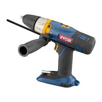
1/2 in., 18 VOLT HAMMER DRILL
2-SPEED
P211
BATTERIES AND CHARGERS
SOLD SEPARATELY
Advertisement
Table of Contents

Related Manuals for Ryobi P211


Summary of Contents for Ryobi P211
- Page 1 Your hammer drill has been engineered and manufactured to our high standard for dependability, ease of operation, and operator safety. When properly cared for, it will give you years of rugged, trouble-free performance. WARNING: To reduce the risk of injury, the user must read and understand the operator's manual before using this product.
-
Page 2: Table Of Contents
The replacement power tool will be covered by the limited warranty for the balance of the two year period from the date of the original purchase. WHAT THIS WARRANTY COVERS: This warranty covers all defects in workmanship or materials in your RYOBI power ®... -
Page 3: General Safety Rules
Use of a cord suit- able for outdoor use reduces the risk of electric shock. n Use battery only with charger listed. MODEL BATTERY PACK (P100) CHARGER (P110) P211 130255004 or 130224028 PERSONAL SAFETY n Stay alert, watch what you are doing and use common sense when operating a power tool. -
Page 4: Specific Safety Rules
n Use the power tool, accessories and tool bits etc., in accordance with these instructions and in the manner intended for the particular type of power tool, taking into account the working conditions and the work to be performed. Use of the power tool for operations dif- ferent from those intended could result in a hazardous situation. -
Page 5: Safety Rules For Charger
SAFETY RULES FOR CHARGER WARNING! READ AND UNDERSTAND ALL INSTRUCTIONS. Failure to follow all instructions listed below, may result in electric shock, fire and/or serious personal injury. n Before using battery charger, read all instructions and cautionary markings in this manual, on battery charger, battery, and product using battery to prevent misuse of the products and possible injury or damage. -
Page 6: Symbols
Some of the following symbols may be used on this tool. Please study them and learn their meaning. Proper interpreta- tion of these symbols will allow you to operate the tool better and safer. SYMBOL NAME Volts Amperes Hertz Watt Minutes Alternating Current Direct Current... - Page 7 The following signal words and meanings are intended to explain the levels of risk associated with this product. SYMBOL SIGNAL DANGER: WARNING: CAUTION: CAUTION: SERVICE Servicing requires extreme care and knowledge and should be performed only by a qualified service tech- nician.
-
Page 8: Features
PRODUCT SPECIFICATIONS Chuck ... 1/2 in. Keyless Motor ...18 Volt DC Switch...Variable Speed No Load Speed ...0-440/0-1,600/min. Hammer Speed ...0-5,720/0-20,800 BPM* *Blows Per Minute ADJUSTMENT RING KEYLESS CHUCK MAGNETIC BIT HOLDER MAGNETIC BIT HOLDER MAG TRAY™ FEATURES Clutch...24 position Torque... Maximum 330 in.lb. Charger Input ... -
Page 9: Know Your Hammer Drill
Your drill is equipped with an auxiliary handle for ease of operation and to prevent loss of control. BIT STORAGE Bits provided with the drill can be placed in the storage area, located on the base of the drill. BLOWS PER MINUTE This tool features an impact speed of BPM (Blows Per Minute). -
Page 10: Assembly
If any parts are damaged or missing, please call 1-800-525-2579 for assistance. PACKING LIST Hammer Drill with Auxiliary Handle Assembly Magnetic Bit Holder Bits (2) Lanyard (Not included in combo) Operator’s Manual... - Page 11 CHARGING THE BATTERY PACK Battery packs for this tool are shipped in a low charge con- dition to prevent possible problems. Therefore, you should charge them until the green LED on the front of the charger comes on. NOTE: Batteries will not reach full charge the first time they are charged.
-
Page 12: To Install/Remove Battery Pack
LED. After 30 minutes, reinsert the battery pack in the charger. If the green LED continues to remain on, return battery pack to your nearest Ryobi Authorized Service Center for checking or replacing. NOTE: This situation only occurs when continuous use of the tool causes the batteries to become hot. -
Page 13: Variable Speed
WARNING: Do not hold chuck body with one hand and use power of the drill to tighten the chuck jaws on the drill bit. The chuck body could slip in your hand, or your hand could slip and come in contact with the rotating drill bit. This could cause an accident resulting in serious personal injury. - Page 14 The drill has a two-speed gear train designed for drilling or driving at LO (1) or HI (2) speeds. A slide switch is located on top of the drill to select either LO (1) or HI (2) speed. When using drill in the LO (1) speed range, speed will decrease and unit will have more power and torque.
- Page 15 TORQUE ADJUSTMENT See Figure 10. When using the drill-driver for various driving applications, it becomes necessary to increase or decrease the torque in order to help prevent the possibility of damaging screw heads, threads, workpiece, etc. In general, torque intensity should correspond to the screw diameter.
- Page 16 BIT STORAGE See Figure 11. When not in use, bits provided with the drill can be placed in the storage areas located on the base of the drill. MAG TRAY™ See Figure 12. The magnetic tray conveniently stores screws or other small parts.
- Page 17 Loosen the auxiliary handle assembly by turning the knob counterclockwise. n Adjust the depth stop rod so that the drill bit extends be- yond the end of the rod to the required drilling depth. n Tighten the auxiliary handle assembly by turning the knob clockwise.
-
Page 18: Removing Bits
Open or close the chuck jaws to a point where the open- ing is slightly larger than the bit size you intend to use. Also, raise the front of the drill slightly to keep the bit from falling out of the chuck jaws. -
Page 19: Wood Drilling
Secure the material to be drilled in a vise or with clamps to keep it from turning as the drill bit rotates. n Hold the drill firmly and place the bit at the point to be drilled. n Depress the switch trigger to start the drill. -
Page 20: Maintenance
Only the parts shown on the parts list are intended to be repaired or replaced by the customer. All other parts should be replaced at a Ryobi Authorized Service Center. BATTERY PACK REMOVAL AND PREPARATION FOR RECYCLING Consult your local waste authority for information regarding available recycling and/or disposal options. -
Page 21: Chuck Removal
Insert a 5/16 in. or larger hex key into the chuck of the drill and tighten the chuck jaws securely. n Tap the hex key sharply with a mallet in a clockwise di- rection. This will loosen the screw in the chuck for easy removal. -
Page 22: Parts Ordering / Service
Please record the model number and serial number in the space provided below. • HOW TO ORDER REPAIR PARTS When ordering repair parts, always give the following information: • MODEL NUMBER • SERIAL NUMBER Ryobi is a registered trademark of Ryobi ® 983000-749 10-05 (REV:01) OPERATOR’S MANUAL 1/2 in./18 VOLT HAMMER DRILL...