Table of Contents
Advertisement
Quick Links
Instruction Manual
Form 5468
June 2010
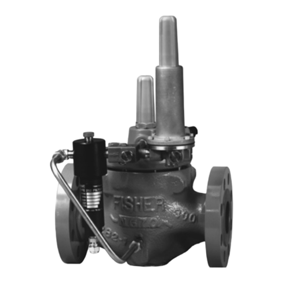
Type Ezr Pressure Reducing Regulator
W7430
161AY SERIES PILOT
WARnInG
!
Failure to follow these instructions or
to properly install and maintain this
equipment could result in an explosion
and/or fire causing property damage and
personal injury or death.
Fisher
regulators must be installed,
®
operated, and maintained in accordance
with federal, state, and local codes, rules
and regulations, and Emerson Process
Management Regulator Technologies,
Inc. instructions.
If the regulator vents gas or a leak
develops in the system, service to the unit
may be required. Failure to correct trouble
could result in a hazardous condition.
Call a gas service person to service
the unit. Only a qualified person must
install or service the regulator.
W7399
TYPE EZR REGULATOR
Figure 1. Type EZR Pressure Reducing Regulator
Introduction
Scope of the Manual
This instruction manual provides installation, startup,
adjustment, maintenance, and parts ordering
information for Type EZR pressure reducing regulator,
Type 112 restrictor, 161AY Series pilot, 161EB Series
pilot, and PRX Series pilot. Any accessories used
with this regulator are covered in their respective
instruction manuals.
Product Description
The Type EZR pilot-operated, pressure reducing
regulators are used for natural gas, air, or other
non-corrosive gas applications and include a Type 112
restrictor and a 161EB, 161AY, or PRX Series pilot. For
applications that have high-pressure drops, using a
Type 161AYM or 161EBM monitor pilot will increase the
accuracy of the regulator.
www.fisherregulators.com
Type EZR
W8346
TYPE PRx PILOT
Advertisement
Table of Contents

Related Manuals for Fisher EZR


Summary of Contents for Fisher EZR
- Page 1 W7430 W8346 161AY SERIES PILOT TYPE PRx PILOT W7399 TYPE EZR REGULATOR Figure 1. Type EZR Pressure Reducing Regulator Introduction WARnInG Scope of the Manual Failure to follow these instructions or to properly install and maintain this This instruction manual provides installation, startup,...
- Page 2 4. NPS 6 x 4, 8 x 4, 8 x 6, 12 x 6 (DN 150 x 100, 200 x 100, 200 x 150, 300 x 150) Types EZR and 399 bodies are not the same as the EW valve bodies and are not interchangeable.
- Page 3 TYPE 252 PILOT SUPPLY FILTER B2625_2 FLOw DIRECTION MAIN SPRING DIAPhRAGM AND PLUG ASSEMBLY W7438 TYPE EZR wITh TYPES 161EB PILOT, 112 RESTRICTOR, AND 252 FILTER TYPE PRx PILOT TYPE 252 SUPPLY FILTER RESTRIcTOR DAMPER PORT S PORT B PORT L...
- Page 4 (control) line. This pilot is used in monitoring systems disk close. Loading pressure begins building on the requiring an isolated pilot bleed (exhaust). Type EZR diaphragm and plug assembly. The loading Type 161EB—High accuracy pilot with an outlet pressure, along with force from the main spring, pressure range of 5 to 350 psig (0,34 to 24,1 bar).
- Page 5 Type 161AYM or 161EBM monitor pilot will increase the Type PRX/120-AP—Outlet pressure range of 435 to accuracy of the regulator. 1000 psig (30,0 to 69,0 bar). The Type PRX/120-AP can be used as the pilot on single-stage pressure Type EZR Installation reducing regulators, as the monitor pilot or working pilot in wide-open monitor systems, or as the working WARnInG pilot for monitoring and working regulators in the working monitoring systems.
- Page 6 All Installations To avoid such injury or damage, provide The robust design of the Type EZR allows this regulator pressure-relieving or pressure-limiting to be installed indoors or outdoors. When installed devices (as required by the appropriate...
- Page 7 (key 23) and vice versa. other foreign material) point the vent down, orient it to the lowest possible point on the spring 2. A Type EZR regulator may be installed in any case or otherwise protect it. Inspect the vent orientation, as long as flow through the regulator ...
- Page 8 2 of underside of the pilot) of the upstream Type PRX-120 pilot this section. to the intermediate pressure between the first and second Type EZR regulators as shown in Figure 5. 2. Pilot supply pressure for the downstream Type EZR regulator must be made directly The “L” port of the upstream Type PRX-125 pilot upstream of the Type EZR using is plugged. Connect the “B” port of upstream ...
- Page 9 SUPPLY VALVE PRESSURE LInE SUPPLY TYPE PRX-125 PRESSURE TYPE PRX-120 hAND MONITOR PILOT LInE wORKING PILOT VALVE cOnTROL LInE ALTERnATE (1) PLUGGED cOnTROL LInE TYPE PRX wORKING MONITOR SYSTEM INSTALLATION Figure 4. Typical Type EZR Monitoring System Installation Schematics...
- Page 10 Do not The pilot supply pressure connection for the exceed maximum pilot ratings given in Table 3. downstream Type EZR regulator must be directly upstream of the Type EZR using intermediate pressure Startup and Adjustment and connected to the “S” port of the downstream Type PRX-120. Install a Type 252 pilot supply filter ...
- Page 11 Type EZR 2. Back out the pilot adjusting screw(s). 3. For easy initial startup, set the restrictor to the “8” position. For future startups, the restrictor can be left in the desired run position. 4. SLOWLY OPEn the valves in the following order: a. Pilot supply and control line valve(s), if used ...
- Page 12 TYPE 112 RECOMMENDED RESTRIcTOR PILOT RESTRIcTOR ORIFIcE SIZE(S) SETTINGS AND Type EZR should be installed. During design of a TYPE SETTInGS FOR FOR LOW FLOW ORIFIcE SIZES TO regulator installation, the downstream piping volume LOW FLOW OPERATIOn AVOID LOw FLOw...
- Page 13 Fair Good 1. The NPS 6 (DN 150), 17E97 diaphragm will perform in gas temperatures as low as -20°F (-29°C). 2. For differential pressures above 400 psig (27,6 bar) diaphragm temperature is limited to 150°F (66°C). 3. The aromatic hydrocarbon content is based on percent volume. Table 9. Type EZR Working Monitor Performance MONITORING PILOT MINIMUM PRESSURE OVER NORMAL DISTRIBUTION PRESSURE AT whICh MONITOR PILOT CAN BE SET Construction...
- Page 14 Type EZR Table 10. Main Valve Maximum Pressure Ratings, Diaphragm Selection Information, and Main Spring Selection MAXIMUM MAXIMUM MAXIMUM OPERATInG EMERGENCY INLET BODY SIZE, DIAPhRAGM OPERATInG InLET MAIN SPRING DIAPhRAGM DIFFERENTIAL AND DIFFERENTIAL NPS (DN) MATERIAL PRESSURE COLOR CODE DESIGNATION...
- Page 15 Type EZR LOADING CONNECTION: 1/4 NPT PIPE CONNECTS TO TYPE EZR DIAPhRAGM LOADING PORT PILOT SUPPLY CONNECTION: 1/4 NPT PIPE CONNECTS TO UPSTREAM PILOT SUPPLY TAP OUTLET CONNECTION: 1/4 NPT PIPE cOnnEcTS TO PILOT InLET cOnnEcTIOn OPTIONAL LOADING CONNECTION: 11B5004-A...
- Page 16 Fisher E-body to a Type EZR. ® cAUTIOn when installing a Type EZR trim package make sure flow is up through the center of the cage and down through the cage slots. In some cases, correct flow path is achieved by removing the body from the line and turning it around.
- Page 17 cage before placing in the body. Lightly lubricate breakage and unit failure. The bonnet the lower adaptor O-rings (keys 121 and 67) and can be identified by the Type EZR place the lower adaptor on a flat surface. Then markings on the top. press the cage down into the lower adaptor.
- Page 18 Type EZR DIAPhRAGM (KEY 9) BOTTOM PLUG (KEY 11) O-RING FLANGED (KEY 14) LOCKNUT (KEY 13) O-RING TOP PLUG (KEY 70) (KEY 5) O-RING (KEY 10) W7394 Figure 9. Diaphragm and Plug Assembly Components 2. Remove the flanged locknut (key 13) from WARnInG the bottom plug (key 11). This loosens the ...
- Page 19 Type EZR INDICATOR FITTING MAIN SPRING UPPER SPRInG (KEY 19) (KEY 12) SEAT (KEY 17) INDICATOR STEM O-RING (KEY 15) (KEY 18) HEx nUTS (KEY 4) INDICATOR COVER (KEY 21) BACK-UP RInGS INDICATOR (KEY 16) wAShER (KEY 79) O-RING (KEY 6)
- Page 20 Type EZR Diaphragm Parts 1. Remove the closing cap (key 16), loosen the locknut (key 12), and back out the adjusting screw (key 11) until compression is removed from the control spring (key 9). 2. Remove the machine screws (key 13, not shown) and separate the spring case (key 2) from the body (key 1). Remove the control spring seat (key 8), the control spring (key 9). If used, remove the diaphragm limiter (key 10). Replace if necessary. W4570-1 3. Remove the diaphragm assembly (key 7) and Figure 11. 161EB Series Pilot Trim Removal/Installation inspect the diaphragm.
- Page 21 Type EZR 4. Install the replacement closing cap gasket (key 25) if necessary and reinstall the closing cap (key 22). BODY SEAL O-RING (KEY 11) 5. If the spring was changed, be sure to change the stamped spring range on the nameplate. BACK-UP RING (KEY 50) BODY (KEY 1) To Disassemble and Reassemble Diaphragm Parts ...
- Page 22 Type EZR from the body (key 16), unless removed during lower diaphragm maintenance. Use a wrench to hold stem (key 23) securely while removing the stem nut (key 26). 5. Remove remaining loose components: washer (key 11), upper diaphragm plate (key 13), diaphragm (key 14), lower diaphragm plate (key 15), and O-rings (keys 18 and 25). Inspect W4573 diaphragm and O-rings for damage or wear, and Figure 13. Pushing Groove Valve Up With Retainer replace if necessary. 3. Use a wrench to hold the stem (key 23) and 6. Lightly lubricate the O-ring (key 25). Place O-ring loosen the stem nut (key 20). Remove the stem over the stem (key 23) and press it down into the nut and washer (key 11).
- Page 23 Parts List Valve Body See Table 14 Type EZR Main Valve (Figures 14 to 18) Bonnet Assembly NPS 1 and 1-1/4 x 1 (DN 25 and 32 x 25) bodies 39B2403X022 NPS 2 x 1 and 2 (DN 50 x 25 and 50) bodies...
- Page 24 Type EZR Table 14. Type EZR Main Valve Body Part Numbers (key 1, Figure 14) BODY STYLE BODY SIZE, BODY END CONNECTION Standard NPS (DN) MATERIAL STYLE Tapped Inlet and Tapped Outlet (Included Tapped Inlet) GE11581X012 - - - - GE11440X012 CL150 RF ...
- Page 25 Type EZR Table 14. Type EZR Main Valve Body Part Numbers (key 1, Figure 14) (continued) BODY STYLE BODY SIZE, END CONNECTION BODY MATERIAL Standard NPS (DN) STYLE Tapped Inlet and Tapped Outlet (Included Tapped Inlet) CL150 RF GE19084X012 CL300 RF...
- Page 26 Type EZR Description Part Number Description Part Number 10* O-ring 14* Top Plug O-ring (continued) NPS 1, 1-1/4 x 1, 2 x 1 and 2 NPS 2 (DN 50) body (DN 25, 32 x 25, 50 x 25, and 50) bodies...
- Page 27 (DN 25, 32 x 25, 50 x 25, 50, 80, 100, 150 x 100, AND 200 x 100) BODY SIZES (NOTE: SEE NPS 2 x 1 (DN 50 X 25) ASSEMBLY FOR ADDITIONAL PARTS) Figure 14. Type EZR Main Valve...
- Page 28 Type EZR Description Part Number Description Part Number 67 O-ring (continued) Indicator Washer (continued) NPS 8 x 6 (DN 200 x 150) body NPS 8 (DN 200) body 20C2461X012 Nitrile (NBR) 1V335006562 21 Indicator Cover Fluorocarbon (FKM) 1V3350X0012 NPS 1, 1-1/4 x 1, 2 x 1, and 2 ...
- Page 29 2 x 1 (DN 50 x 25) MAIN VALVE ASSEMBLY (DN 150, 200 x 150, AND 300 x 150) BODY SIZES NPS 8 x 6 (DN 200 x 150) RESTRICTOR PLATE O-RING PLACEMENT Figure 14. Type EZR Main Valve (continued)
- Page 30 Type EZR APPLY LUBRICANT/SEALANT/ADhESIVE PARTS NOT ShOwN: 63 40C3570-C MAIN VALVE ASSEMBLY FOR NPS 8 (DN 200) BODY Figure 14. Type EZR Main Valve (continued)
- Page 31 Type EZR B2617_A2 Figure 15. Type EZR Nameplate and Flow Arrow B2617_C B2617_D Figure 16. Type EZR Restricted Trim Figure 17. Type EZR Cage O-ring Placement B2617_E NPS 1, 1-1/4 x 1, 2 x 1, 2, 3, AND 4 nPS 6 x 4, 8 x 4, 6, 8 x 6, 12 x 6...
- Page 32 Type EZR 30B4395-E APPLY LUBRICANT/SEALANT/ADhESIVE TYPE 161EB PILOT SEnSE (cOnTROL) PORT SEnSE (ExHAUST) PORT 31B5012-A TYPE 161EBM PILOT Figure 19. 161EB Series Pilots...
- Page 33 Type EZR Type EZR Main Valve (Figures 14 to 18) (continued) Description Part Number Description Part Number 1 Body Assembly, CF8M Stainless steel 130 Lock Washer Types 161EB 1B7971X0252 For NPS 1, 1-1/4 x 1, and 2 x 1 Types 161EBM 30B8715X012 (DN 25, 32 x 25, and 50 x 25) only 1A329128982 ...
- Page 34 Type EZR TYPE 161AY B2631 B2632 B2631 TYPE 161AYM Figure 20. Types 161AY and 161AYM Pilots...
- Page 35 Type EZR 34B7733A 30B4383 OPTIONAL QUICK DISCONNECT UNION PILOT MOUNTING STANDARD PILOT MOUNTING Figure 21. 161EB Series Mounting Parts Type 161AY or 161AYM Pilot (Figure 20) Description Part Number Description Part Number Parts Kit (included are keys 10, 11, 12, 13, 15, 25, Guide Insert 27B4028X022 30, 31, 33, 45, 48, and 49)
- Page 36 Type EZR 161EB Series Mounting Parts (Figure 21) For Working Monitor Set Standard Configuration Description Part Number 4 Nut, SA194 (2 required) 1C330624072 Description Part Number Pipe Nipple, Plated Steel NPS 1 and 1-1/4 x 1 Pipe Nipple, Plated steel (DN 25 and 32 x 25) bodies...
- Page 37 1 NPS 4 (DN 100) BODY ONLY TYPE 161AY PILOT MOUNTING FOR NPS 1 ThROUGh 4 MOUNTING FOR nPS 1 THROUGH 6 (DN 25 ThROUGh 100) TYPE EZR REGULATOR (DN 25 ThROUGh 150) TYPE EZR REGULATOR Type EZR NPS 1 (DN 25) ONLY...
- Page 38 OR 161M TYPE 112 TYPE 252 TYPE 161AYM 41B5009 37B8952 Figure 25. Pounds to Inches (161AY/161EB Series Pilots) Figure 26. Pre-piped Type EZR with Type 161EB Pilot, Monitor System Mounting Parts Type 112 Restrictor, and Type 252 Pilot Supply Filter...
- Page 39 Type EZR Pre-piped Pilot Supply (Figure 26) Description Part Number 59 Pipe Nipple, for use without Type 252 filter NPS 1 (DN 25) body - - - - - - - - - - - NPS 2, 3, and 4 (DN 50, 80, and 100) bodies...
- Page 40 Type EZR PRX Series Pilots (Figure 27) Description Part Number Description Part Number Parts Kits 17* Orifice O-ring See Parts Kits Elastomer Parts Kits (includes keys: 4, 5, 14, 17, 18* Lower Cover O-ring See Parts Kits 18, 25, and 28) 19 Orifice GD25344X012 Types PRX/120 and PRX/125...