Mitsubishi Electric MLZ-KP25VF Service Manual
Hide thumbs
Also See for MLZ-KP25VF:
- Operating instructions manual (208 pages) ,
- Installation manual (12 pages) ,
- Installation manual (12 pages)
Table of Contents
Advertisement
INDOOR UNIT
SERVICE MANUAL
Models
MLZ-KP50VF
NOTE:
RoHS compliant products have <G> mark on the spec name plate.
-
E1
ER1
,
-
E1
ER1
,
-
E1
ER1
,
CONTENTS
1. TECHNICAL CHANGES ··································· 2
2. SAFETY PRECAUTION ···································· 3
3. PART NAMES AND FUNCTIONS ···················· 7
MLZ-KP25VF
4. SPECIFICATION ··············································· 8
MLZ-KP35VF
5. NOISE CRITERIA CURVES ······························ 9
MLZ-KP50VF
6. OUTLINES AND DIMENSIONS ······················ 10
7. WIRING DIAGRAM ···········································11
8. REFRIGERANT SYSTEM DIAGRAM ············· 12
9. SERVICE FUNCTIONS ··································· 13
10. MICROPROCESSOR CONTROL ···················· 16
11. TROUBLESHOOTING ····································· 24
12. DISASSEMBLY INSTRUCTIONS ··················· 38
PARTS CATALOG (OBB801)
No. OBH801
Outdoor unit service manual
MXZ-D VA Series (OBH626)
MXZ-E VA Series (OBH723)
MXZ-F VF Series (OBH790)
Advertisement
Table of Contents
Troubleshooting

Related Manuals for Mitsubishi Electric MLZ-KP25VF


Summary of Contents for Mitsubishi Electric MLZ-KP25VF
- Page 1 INDOOR UNIT No. OBH801 SERVICE MANUAL Models MLZ-KP25VF MLZ-KP35VF MLZ-KP50VF Outdoor unit service manual MXZ-D VA Series (OBH626) MXZ-E VA Series (OBH723) MXZ-F VF Series (OBH790) CONTENTS 1. TECHNICAL CHANGES ··································· 2 2. SAFETY PRECAUTION ···································· 3 3. PART NAMES AND FUNCTIONS ···················· 7 MLZ-KP25VF 4.
-
Page 2: Technical Changes
Do not touch the hot or cold areas in the refrigeration cycle. When the repair or the inspection of the circuit needs to be done without turning off the power, exercise great caution not to touch the live parts. TECHNICAL CHANGES MLZ-KP25VF- MLZ-KP35VF- MLZ-KP50VF- 1. New model... -
Page 3: Safety Precaution
SAFETY PRECAUTION 2-1. CAUTIONS RELATED TO NEW REFRIGERANT Cautions for units utilizing refrigerant R32/R410A WARNING 1. Warning for service (1) In case of reconnecting the refrigerant pipes after detaching, make the flared part of pipe re-fabricated. (2) This unit should be installed in rooms which exceed the floor space specified in outdoor unit installation manual. Refer to outdoor unit installation manual. - Page 4 (1-8) Checks on the Refrigeration Equipment Where electrical components are being changed, they shall be fit for the purpose and to the correct specification. At all times the manufacturer’s maintenance and service guidelines shall be followed. If in doubt, consult the manufacturer’s technical department for assistance.
- Page 5 (7) Removal and Evacuation When breaking into the refrigerant circuit to make repairs – or for any other purpose conventional procedures shall be used. However, for flammable refrigerants it is important that best practice is followed since flammability is a considera- tion.
- Page 6 (10) Labelling Equipment shall be labelled stating that it has been de-commissioned and emptied of refrigerant. The label shall be dated and signed. For appliances containing flammable refrigerants, ensure that there are labels on the equipment stat- ing the equipment contains flammable refrigerant. (11) Recovery When removing refrigerant from a system, either for servicing or decommissioning, it is recommended good practice that all refrigerants are removed safely.
-
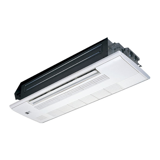
Page 7: Part Names And Functions
PART NAMES AND FUNCTIONS INDOOR UNIT MLZ-KP25VF MLZ-KP35VF MLZ-KP50VF Horizontal vane Vertical vane Air inlet Intake grille Air outlet (Silver-ionized air Display section Spec name plate Safety strings Open the display cover Remote control receiving section Emergency operation switch Operation indicator lamp... - Page 8 SPECIFICATION Indoor model MLZ-KP25VF MLZ-KP35VF MLZ-KP50VF Function Cooling Heating Cooling Heating Cooling Heating Single phase Single phase Single phase Power supply 230V, 50Hz 230V, 50Hz 230V, 50Hz Capacity Air fl ow (High/Med./Low/SLow) m /h 528/480/432/360 552/492/420/360 564/504/438/360 594/528/462/360 684/588/498/360 708/618/528/360...
-
Page 9: Noise Criteria Curves
NOISE CRITERIA CURVES MLZ-KP25VF MLZ-KP35VF FAN SPEED FUNCTION SPL(dB(A)) LINE FAN SPEED FUNCTION SPL(dB(A)) LINE COOLING COOLING High High HEATING HEATING Test conditions, Test conditions, Cooling: Dry-bulb temperature 27ºC Wet-bulb temperature 19ºC Cooling: Dry-bulb temperature 27ºC Wet-bulb temperature 19ºC Heating: Dry-bulb temperature 20ºC Heating: Dry-bulb temperature 20ºC... -
Page 10: Outlines And Dimensions
OUTLINES AND DIMENSIONS MLZ-KP25VF MLZ-KP35VF MLZ-KP50VF Unit: mm INDOOR UNIT OBH801... -
Page 11: Wiring Diagram
WIRING DIAGRAM INDOOR UNIT MLZ-KP25VF- MLZ-KP35VF- MLZ-KP50VF- OBH801... -
Page 12: Refrigerant System Diagram
REFRIGERANT SYSTEM DIAGRAM INDOOR UNIT MLZ-KP25VF MLZ-KP50VF Unit: mm MLZ-KP35VF Refrigerant pipe Ø9.52 Refrigerant pipe Ø12.7 (with heat insulator) (with heat insulator) Indoor coil Indoor coil thermistor thermistor Indoor Indoor RT12,RT14, heat heat RT12 (main) RT15 (main) exchanger exchanger Flared connection... -
Page 13: Service Functions
SERVICE FUNCTIONS MLZ-KP25VF MLZ-KP35VF MLZ-KP50VF 9-1. TIMER SHORT MODE • For service, the following set time can be shortened by bridging the timer short mode point on the electronic control P.C. board. (Refer to 11-7.) • The set time for the ON/OFF timer can be reduced to 1 second for each minute. - Page 14 9-3. AUTO RESTART FUNCTION When the indoor unit is controlled with the remote controller, the operation mode, the set temperature, and the fan speed are memorized by the indoor electronic control P.C. board. “AUTO RESTART FUNCTION” automatically starts operation in the same mode just before the shutoff of the main power. Operation If the main power has been cut, the operation settings remain.
- Page 15 9-4. P.C. BOARD MODIFICATION FOR CHANGING AIRFLOW VOLUME Change dip switch SW3 setting according to the height of ceiling. Dip switch SW3 Normal Increase airflow volume Ceiling height 2.4 m or below above 2.4 m and 2.7 m or below NOTE: When the ceiling is above 2.7 m, airflow volume may be insufficient even with the Dip switch (SW3) set to "increase airflow".
-
Page 16: Microprocessor Control
MICROPROCESSOR CONTROL MLZ-KP25VF MLZ-KP35VF MLZ-KP50VF WIRELESS REMOTE CONTROLLER Signal transmitting section Operate the remote control- ler in the area where signal is Distance of signal: About 6 m received, and beep is heard. Beep(s) is (are) heard from the indoor unit when the signal is received. - Page 17 10-1. COOL ( ) OPERATION (1) Press STOP/OPERATE(OFF/ON) button. OPERATION INDICATOR lamp of the indoor unit turns on with a beep tone. (2) Select COOL mode with OPERATION SELECT button. (3) Press TEMPERATURE buttons TEMP button to select the desired temperature. The setting range is 16 - 31°C. 1.
- Page 18 NOTE 2 FOR MULTI SYSTEM AIR CONDITIONER OUTDOOR UNIT: MXZ series Multi system air conditioner can connect 2 or more indoor units with one outdoor unit. • When you try to operate 2 or more indoor units with one outdoor unit simultaneously, one for the cooling and the others for heating, the operation mode of the indoor unit that operates first is selected.
- Page 19 (6) SWING ( ) mode By selecting SWING mode with VANE CONTROL button, the horizontal vanes swing vertically. When COOL, DRY or FAN mode is selected, only the upper vane swings. (7) Cold air prevention in HEAT operation The horizontal vane position is set to upward. (8) ECONO COOL ( ) operation (ECONOmical operation) When ECONO COOL button is pressed in COOL mode, set temperature is automatically set 2°C higher by micro- processor.
- Page 20 10-8. TIMER OPERATION 1. How to set the time (1) Check that the current time is set correctly. NOTE: Timer operation will not work without setting the current time. Initially “0:00” blinks at the current time display of TIME MONITOR, so set the current time correctly with CLOCK SET button. How to set the current time (a) Press the CLOCK set button.
- Page 21 10-9. WEEKLY TIMER OPERATION • A maximum of 4 ON or OFF timers can be set for individual days of the week. • A maximum of 28 ON or OFF timers can be set for a week. NOTE: The simple ON/OFF timer setting is available while the weekly timer is on. In this case, the ON/OFF timer has priority over the •...
- Page 22 (4) Press button to complete and transmit the weekly timer setting. which was blink- ing goes out, and the current time will be displayed. NOTE: • Press button to transmit the setting information of weekly timer to the indoor unit. Point the remote controller toward the indoor unit for 3 seconds.
- Page 23 10-11. EMERGENCY/TEST OPERATION In the case of test run operation or emergency operation, use EMERGENCY OPERATION switch on the right side of the indoor unit. Emergency operation is available when the remote controller is missing or has failed, or the batteries in the remote controller are running down.
-
Page 24: Troubleshooting
TROUBLESHOOTING MLZ-KP25VF MLZ-KP35VF MLZ-KP50VF 11-1. CAUTIONS ON TROUBLESHOOTING 1. Before troubleshooting, check the following: 1) Check the power supply voltage. 2) Check the indoor/outdoor connecting wire for miswiring. 2. Take care of the following during servicing 1) Before servicing the air conditioner, be sure to turn off the unit first with the remote controller, and then after confirming the horizontal vane is closed, turn off the breaker and/or disconnect the power plug. - Page 25 11-2. FAILURE MODE RECALL FUNCTION Outline of the function This air conditioner can memorize the abnormal condition which has occurred once. Even though LED indication listed on the troubleshooting check table (11-4.) disappears, the memorized failure details can be recalled. 1.
- Page 26 2. Flow chart of the detailed outdoor unit failure mode recall function Operational procedure The outdoor unit might be abnormal. Check if outdoor unit is abnormal according to the following procedures. Make sure that the remote controller is set to the failure mode recall function.
- Page 27 3. Indoor unit failure mode table NOTE: Blinking patterns of this mode differs from the ones of Troubleshooting check table (11-4.). Left lamp of Right lamp of Abnormal point OPERATION OPERATION Condition Remedy (Failure mode) INDICATOR lamp INDICATOR lamp Not lit Not lit Normal —...
- Page 28 11-3. INSTRUCTION OF TROUBLESHOOTING Start Indoor unit Indoor unit Indoor unit operates. OPERATION INDICATOR operates. does not receive Outdoor unit does not lamp on the indoor unit is Outdoor unit the signal from operate normally. flashing on and off. does not remote controller.
- Page 29 11-4. TROUBLESHOOTING CHECK TABLE OPERATION INDICATOR · Flashing of OPERATION INDICATOR lamp (left-hand side lamp) indicates abnormalities. Blinking Not lit NOTE: Before taking measures, make sure that the symptom reappears for accurate troubleshooting. Self check table Abnormal Operation indicator lamp Symptom Condition Remedy...
- Page 30 NOTE: When the indoor unit has started operation and the above failures are detected (the first detection after the power ON), the indoor electronic control P.C. board turns OFF the indoor fan motor with OPERATION INDICATOR lamp flashing. 11-5. TROUBLE JUDGEMENT CRITERIA OF MAIN PARTS MLZ-KP25VF MLZ-KP35VF MLZ-KP50VF Part name Check method and criteria...
-
Page 31: Troubleshooting Flow
11-6. TROUBLESHOOTING FLOW When the left lamp of OPERATION INDICATOR lamp flashes 3 times and the right lamp of OPERATION INDICATOR lamp is not lighted. Indoor fan does not operate. Check of indoor fan motor The indoor fan motor error has occurred, and the indoor fan does not operate. Turn OFF the power supply. - Page 32 Indoor unit operates by pressing EMERGENCY OPERATION switch, but does not operate with the remote controller. Check of remote controller, receiver P.C. board and indoor electronic control P.C. board Check if the remote controller is exclusive for this air conditioner. Press STOP/OPERATE (OFF/ON) button on the remote controller.
- Page 33 The unit cannot be operated with the remote controller. Also, OPERATION INDICATOR lamp does not light up by pressing EMERGENCY OPERATION switch. Check of indoor electronic control P.C. board and indoor fan motor Turn OFF the power supply. Remove indoor fan motor connector CN211 and vane Turn OFF the power supply.
- Page 34 When the left lamp of OPERATION INDICATOR lamp flashes ON and OFF in every 0.5-second. Outdoor unit does not operate. How to check miswiring and serial signal error Turn OFF the power supply. Is there rated voltage of Check the power 230 V AC in the power supply.
- Page 35 When the left lamp of OPERATION INDICATOR lamp flashes 9-time. Indoor unit and outdoor unit do not operate. Check of float sensor Turn OFF the power supply and check connectors CN145 and CN1N1 visually. Are there abnormality in Are the lead wires Replace the indoor Connect the lead wire.
- Page 36 Electromagnetic noise enters into TV sets or radios Is the unit earthed? Earth the unit. Is the distance between the antennas Extend the distance between the antennas and and the indoor unit within 3 m, or is the the indoor unit, and/or the antennas and the distance between the antennas and the outdoor unit.
- Page 37 11-7. TEST POINT DIAGRAM AND VOLTAGE MLZ-KP25VF Factory setting MLZ-KP35VF (Do not change the setting.) MLZ-KP50VF SW101 Indoor electronic control P.C. board NR11 CN1N1 CN145 CN202 Varistor Drain pump Float sensor Serial signal R111 F11 FUSE T3.15AL250V CN201 Power supply...
-
Page 38: Disassembly Instructions
Locking lever lever. Connector MLZ-KP25VF MLZ-KP35VF MLZ-KP50VF NOTE: Turn OFF the power supply before disassembly. OPERATING PROCEDURE PHOTOS/FIGURES Photo 1 1. Removing the intake grille (1) Slide the tabs (2 places) of intake grille in the direction... - Page 39 OPERATING PROCEDURE PHOTOS/FIGURES Figure 5 2. Removing the grille (1) Remove the intake grille. (2) Remove the fixing screws for side panels (2 screws) on the left and right sides (Figure 5). Attach to the hook of grille. (3) Open the side panels on the left and right sides. Screw cap Remove the safety strings from the grille and remove the side panels (Figure 5).
- Page 40 OPERATING PROCEDURE PHOTOS/FIGURES (7) Install the screw cap. Figure 9 (8) After attaching the safety strings for the left and right side panels to the grille, install the side panels (Figure NOTE: Make sure that the tabs of the side panels securely fit into place (Figure 9).
- Page 41 OPERATING PROCEDURE PHOTOS/FIGURES Photo 2 3. Removing the indoor electric control P.C. board, the receiver P.C. board and the display P.C. Fixing screw of Drain pan the electrical box board (1) Remove the intake grille. (2) Remove the side panel (L). (3) Remove the electrical cover (4 fixing screws) (Photo 2).
- Page 42 Motor band these 2 items.) Safety string Fan motor HEAD OFFICE: TOKYO BUILDING, 2-7-3, MARUNOUCHI, CHIYODA-KU, TOKYO 100-8310, JAPAN © Copyright 2018 MITSUBISHI ELECTRIC CORPORATION Published in Feb. 2018 No. OBH801 Made in Japan Specifications are subject to change without notice.