
Related Manuals for RTS CLD Color Keypanel Family DKP 16 CLD


Summary of Contents for RTS CLD Color Keypanel Family DKP 16 CLD
-
Page 1: User Manual
CLD Color Keypanel Family User Manual KP 32 CLD DKP 16 CLD EKP 32 CLD 93507858000 Rev B 8/2008... - Page 2 Telex is prohibited. ARRANTY OTICE See the enclosed warranty card for further details. USTOMER UPPORT Technical questions should be directed to: Customer Service Department RTS/Telex Communications, Inc. 12000 Portland Avenue South Burnsville, MN 55337 USA Telephone: 800-392-3497 Fax: 800-323-0498 ETURN HIPPING NSTRUCTIONS Customer Service Department Telex Communications, Inc.
-
Page 3: Table Of Contents
INTRODUCTION ... 3 Features ...3 Specifications ...4 KP 32 CLD Block Diagram ...5 Reference View - KP 32 CLD (90007858000) ...6 ...6 RONT ANEL ESCRIPTIONS ...7 ANEL ESCRIPTIONS GPI 32 CLD M PTIONAL ODULE Reference View DKP 16 CLD (90007866000) ...8 ...8 RONT ANEL... - Page 4 UDIO PTIONS PEAKER UDIO PTIONS UDIO PTIONS REAMP Menu System, Display ... 78 ...79 ISPLAY SSIGN ...80 ISPLAY HANS ...80 ISPLAY HIME ...81 ISPLAY XCLUSIVE ...81 ISPLAY ROUPS ...82 ISPLAY 2 ...83 ISPLAY EVEL ...83 ISPLAY ISTEN ...84 ISPLAY ATRIX ID ...84 ISPLAY ANEL...
- Page 5 KP 32 CLD Inside Switch Bank ... 15 FIGURE 10. Use this switch setting scheme for RTS Standard Cable (USOC)..16 FIGURE 11. Use this switch setting scheme for a Standard CAT-5 Cable using pin 1 and pin 2 for RS485 functionality (568B)..16 FIGURE 12.
- Page 6 FIGURE 45. Audio Options - Headset Mic Options ...63 FIGURE 46. Audio Options Key Volume Adjust ...64 FIGURE 47. Audio Options - Key Volume Enabled ...65 FIGURE 48. Audio Options Menu - Key Volume Reset ...65 FIGURE 49. Key Volumes Reset ...66 FIGURE 50.
- Page 7 FIGURE 105. Key Options Menu - Tallies Menu ... 105 FIGURE 106. Key Options Menu - Tally Time Options ... 106 FIGURE 107. RVON Offers Display ... 106 FIGURE 108. Main Save Config Menu ... 107 FIGURE 109. Configuration Saved ... 107 FIGURE 110.
-
Page 9: Introduction
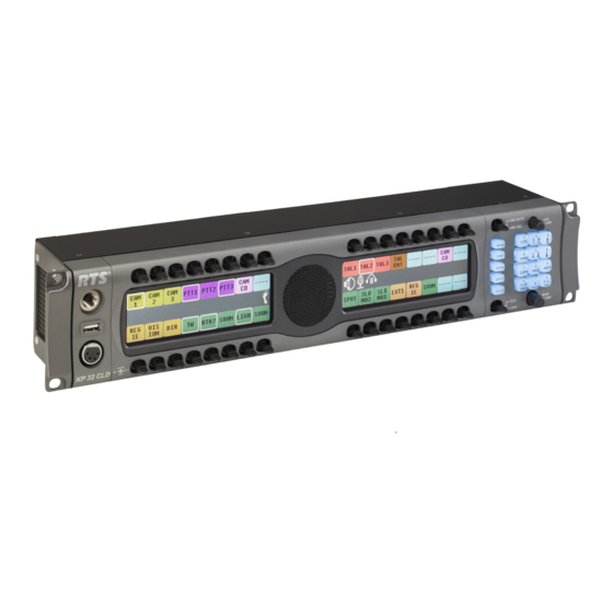
The revolutionary CLD family of keypanels from RTS introduces several new features designed to enhance capability and ease of use. The intuitive graphic interface is housed inside two (2) full-color 4.9” LCD displays. The front panel also features conveniences such as two (2) user-programmable buttons, one-touch listen volume adjustment on each of the 32 new multifunction user keys, and a backlit keypad. -
Page 10: Specifications
XLR(Female) Headset” on page 11 for pinouts). USB Type A Keypanel Audio DB-9, RJ-45 (Supports RTS RJ-11 cabling or Input / Output Standard Cat5 cabling) See “RJ-45 Frame (RTS RJ11 Cable)” and “DB-9 (male) Frame” on page 12 for pinouts. -
Page 11: Kp 32 Cld Block Diagram
KP 32 CLD Block Diagram KP 32 CLD Block Diagram FIGURE 1. -
Page 12: Reference View - Kp 32 Cld (90007858000)
Reference View - KP 32 CLD (90007858000) KP 32 CLD Front Panel FIGURE 2. Front Panel Descriptions 1 1/4” Stereo Jack - Panel Mic USB - Data Storage 4- or 5-pin XLR(female) - Headset only connection 6- or 7-pin XLR (female) - Headset and Footswitch connection. Keypanel Keys - Press down to talk, press up to listen. -
Page 13: Rear Panel Descriptions
KP 32 CLD Back Panel and GPI 32 CLD Option Card FIGURE 3. Rear Panel Descriptions AC Power Connector DB-9 (female) Connector - Frame RJ-45 Connector - Frame RJ-45 Connector - Expansion RJ-45 Connector - LCP (for future expansion) Boot Loader Reset - For more information, see “Download Firmware Using the BLR Function”... -
Page 14: Reference View Dkp 16 Cld (90007866000)
Reference View DKP 16 CLD (90007866000) DKP 16 CLD - Top View FIGURE 4. Front Panel Descriptions 1 1/4” Stereo Jack - Panel Mic Keypanel Keys - Press down to talk, press up to listen. For more information, see “Basic Intercom Key Operation”... - Page 15 DKP 16 CLD Front, Right and Left Side Views FIGURE 5. USB - Data Storage Right side 4-, 5-pin XLR(female) for Headset. 6-, 7-pin XLR(female) for Headset and Footswitch connection. Left side 4-, 5-pin XLR(female) for Headset. 6-, 7-pin XLR(female) for Headset and Footswitch connection.
- Page 16 DKP 16 CLD Back View FIGURE 6. AC/Power Boot Loader Reset - For more information, see “Download Firmware Using the BLR Function” on page 42. DB-9 (female) Connector - Frame RJ-45 Connector - Frame XLR-3 (female) Connector - Aux 1 XLR-3 (female) Connector - Aux 2 DB-9 Connector - Aux 3, Footswitch and Speaker DB-9 (male) Connector - Opto 1-3 IN...
-
Page 17: Connector Pinouts
Connector Pinouts USB Type A USB 5V Data - Data + DGND 1 1/4” Stereo Jack (Panel Mic) Audio + and DC Bias Ring Sleeve Chassis GND 4-, 5-, 6-, 7-pin XLR(Female) Headset 4-pin 5-pin Pin 1 MIC + MIC + MIC + Pin 2 GND(MIC) GND (MIC) GND (MIC) - Page 18 Audio OUT (to Matrix) - Data Shield Audio IN (from Matrix)- Audio IN (from Matrix)+ Audio OUT (from Matrix) shield RJ-45 Frame (RTS RJ11 Cable) Assignment RS485 - Audio IN (from Matrix) + Audio OUT (to Matrix) + Audio OUT (to Matrix) -...
- Page 19 RJ-45 Frame (Standard Cable) Assignment RS485 + (pair 1&2) RS485 - (pair 1&2) Audio IN (from Matrix) + Audio OUT (to Matrix) + Audio OUT (to Matrix) - Audio IN (from Matrix) - RS485 + (pair 7&8) RS485 - (pair 7&8) RJ-45 EXP (expansion) Assignment RS485 +...
-
Page 20: Accessing The Switch Bank
Accessing the Switch Bank To access the switch bank, do the following: Remove the four (4) screws on the top of the unit (shown in Figure 7). KP 32 CLD Top Screw Removal. FIGURE 7. In no certain order, remove the following screws (shown in Figure 8). KP 32 CLD Back Panel Screw Removal FIGURE 8. - Page 21 Carefully lift the chassis up and back to remove the back panel. Note, the back panel is still attached by the DB-9 Frame ribbon cable. KP 32 CLD Inside Switch Bank FIGURE 9. Using a pointed object, set the switches to the type of operation you desire. For operation modes, see Figure 10, Figure 11, or Figure 12.
- Page 22 Use this switch setting scheme for RTS Standard Cable (USOC). FIGURE 10. Use this switch setting scheme for a Standard CAT-5 Cable using pin 1 and pin 2 for RS485 FIGURE 11. functionality (568B). Use this switch setting scheme for a Standard CAT-5 Cable using pin 7 and pin 8 for FIGURE 12.
-
Page 23: Installation
Figure 13). Connect a DB9 cable (G) to the DB9 frame connector (see Figure 13). Using the KP 32 CLD and AZedit, configure your keypanel for operation. ® cabling (E) or RJ45 cable with RTS CHAPTER 2 Installation ® cabling (F) to the frame connector (see... -
Page 24: Power Up
Power Up Connect a power cord to the unit and then to an AC power source. The power supply accepts 100-240 VAC, 50/60 Hz. At power-up, if the keypanel is connected to the matrix, the alphanumeric display shows dashes in the light blue color key . -
Page 25: Connections
Connections Frame Connector Use either of the Frame connectors (but not both) to connect to an intercom port of the intercom system. For frame connector locations, see Figure 3 on page 7. The intercom port you connect to should agree with the address you set previously. Headset Connector A stereo headset may be connected to the front of the unit (or rear, with optional GPI 32 CLD option card installed) for use along with or in place of the front/rear panel speaker and a separate microphone. -
Page 27: Basic Operation
Intercom Keys and Displays Color Display Descriptions for Intercom Keys The KP 32 CLD display uses key colors to distinguish the type of key assignment assigned to the key. Use Table 2, Default Key Colors, to help you determine the available key assignment colors. TABLE 2. -
Page 28: Display Icons
Display Icons Display icons are used to indicate the accessories and features enabled, disabled, active, and inactive. Use Table 3 for a complete description of each icon seen on the KP 32 CLD. Display Icon Descriptions TABLE 3. Icon Icon Name Matrix Connected Disconnected... - Page 29 Display Icon Descriptions TABLE 3. Icon Icon Name Front Speaker The front speakers are muted. To mute the front speaker, see “Mute the Microphone/ Muted Speaker” on page 34. Rear The rear headphones are active. To activate the rear headphones, see “Audio Options Headphones Menu, Headset”...
-
Page 30: Default Keypad
Display Icon Descriptions TABLE 3. Icon Icon Name Both Microphones Muted Both Speakers Both Speakers Muted Snoop Tally Active Hot Mic Tone 1kHz Enabled Tone 500Hz Enabled Main Volume User Volume Default Keypad There are two (2) different keypad sequences you can apply to the KP 32 CLD unit, the Default keypad sequence and the Classic keypad sequence. -
Page 31: Default Keypad
To select the keypad sequence desired, do the following: On the KP 32 CLD, press the MENU button. The top-level menu appears. Using the (3)↑ or (6)↓, scroll to Service. Press the SEL button. The Service menu appears. Using the (3)↑ or (6)↓, scroll to Keypad. Press the SEL button. - Page 32 BACK button UPG 1 button UPG 2 button LOC (1) button TYPE (4) button COPY (7) button CLR/DROP (*) button ↑↑ (2) button ↓↓ (5) button PAGE (8) button PHONE (0) button ↑ (3) button ↓ (6) button The BACK button moves you backward, one level, through the menu structure.
-
Page 33: Info Button
INFO (9) button SEL/DIAL (#) button INFO button The INFO button is used to access commonly used features and configuration options for the KP 32 CLD. These include the following: INFO Button Feature and Option Descriptions TABLE 4. Graphical Representation FEATURE DESCRIPTION Displays the port ID where the keypanel is located... -
Page 34: Intercom Key Operation
INFO Button Feature and Option Descriptions TABLE 4. Displays the firmware version currently loaded on the KP 32 CLD. For more information, see “Display Menu, Version” on page 85. Intercom Key Operation Basic Intercom Key Operation Coupled with the traditional operation of keys, the KP 32 CLD keypanel also has an integrated LCP (level control panel). This feature allows the user to adjust the volume for individual keys on the keypanel. -
Page 35: Key Gain Adjustment
Key Gain Adjustment The Key Gain Adjustment is used to change the crosspoint listen gain on a specific key from the Matrix. This adjustment is automatically reflected in AZedit on the Crosspoint Gains window. (System|Gains|Crosspoint). The range for this feature is Mute, -80dB to +6dB. NOTE: A listen assignment must be configured for key gain to be enabled on a keypanel key. -
Page 36: Aux Volume Adjustments
NOTE: When the MAIN VOLUME encoder is turned, the volume level bar appears in the display window (see Figure 16). Main Volume Adjustment Front Speaker FIGURE 16. NOTE: You can save the volume adjustments to be power-up defaults using “Service Menu, Save Cfg”. To select a different listen destination volume control, do the following: >... - Page 37 To adjust listen volume level, do the following: > On the KP 32 CLD, turn the AUX VOLUME encoder to the right to increase the volume for the listen source. Turn the AUX VOLUME encoder to the left to decrease the volume for the listen source. NOTE: When the AUX VOLUME encoder is turned, the volume level bar appears in the display window (see Figure 16).
-
Page 38: Operation Of Intercom Keys With Auto Functions
Operation of Intercom Keys with Auto Functions NOTE: Assignment of keys with auto functions is described in the programming section that follows. Operation of keys with auto functions, is as follows: Talk+auto follow Talk and listen can be activated separately. The listen assignment listens to whatever is assigned to the talk key. -
Page 39: Operation Of Intercom Keys Assigned To Tif Ports
Operation of Intercom Keys assigned to TIF Ports If a keypanel key is assigned to talk to an intercom port designated as a TIF port in AZedit, placing the key in the talk position activates the KP 32 CLD dialing menu. PROCEDURE: To designate an intercom port as a TIF port, select the Port is TIF check box in AZedit. -
Page 40: Mute The Microphone/Speaker
To answer a CWW call, do the following: > Press down and hold the CWW key to talk back. To clear a name from the CWW window, do the following: > When the CWW window is populated, tap up on the CWW key. NOTE: If a second call is received in the CWW while a caller name is already displayed, the Call Waiting window flashes. -
Page 41: Mic Select
Mic Select The MIC SEL display alternates between Headset and Speaker with each key press. When active the Headset or Speaker icon appear in the keypanel display. To switch between active sources, do the following: > On the KP 32 CLD, press down on the MIC SEL switch (see Figure 2 on page 6). The audio source is changed. - Page 42 Source Configuration Matrix and Display icons TABLE 5. ALWAYS ON/ENABLED Speaker Front and Rear Front Rear Front Rear Headset Front and Rear Front Rear Front Rear NOTE: All four (4) mics cannot be enabled at the same time. If three (3) mic sources are turned ON, the external panel mic is not available.
-
Page 43: User Programmable Keys
User Programmable Keys UPG 1 and UPG 2 (see Figure 2 and Figure 4) gives you the option to assign frequently used menu items to a single key on the keypanel, eliminating the need to navigate through the menu structure. Not all menu items can be programmed to the UPG keys, such as any assignment group menu, any TIF menu items, or scrolling menu items. - Page 44 Using the 3(↑) or 6(↓), select Activate. Press SEL. The screen saver activates on the keypanel. Press and hold the UPG key you want to assign this option to for two (2) seconds. Menu position saved appears in the display window and the screen saver feature is assigned to the UPG key.
-
Page 45: Firmware Download
NOTE: The instructions provided below are applicable for all CLD family keypanels; however, the instructions below display the KP 32 CLD. Download Firmware to the Color Keypanel Family From AZedit Open AZedit. From the Status menu, select Port. The Port Status window appears. Find the port number where the KP 32 CLD is assigned. - Page 46 Highlight the Port (keypanel) to be updated. You may select more than one at a time by holding CTRL key down while you select. Right-click the highlighted selections and select Download Firmware. The Firmware Download window appears. Using the browse button, browse to the file to be downloaded. Click Open.
- Page 47 NOTE: The KP 32 CLD resets itself once the firmware download is complete.
-
Page 48: Download Firmware Using The Blr Function
Verify the version upgrade in the I/O Card Version Information window is correct. Download Firmware Using the BLR Function NOTE: The instructions provided below are applicable for all CLD family keypanels; however, the instructions below display the KP 32 CLD The BLR (Boot Loader Reset) button is used to upload new firmware to a keypanel with a corrupt/bad image installed. - Page 49 Using a screwdriver, press the BLR button located on the back of the keypanel. While the BLR button is pressed, connect the power cord to the keypanel. KP 32 CLD - Boot Loader Waiting for download... appears in the display window. In AZedit, from the Status menu, select Software Versions.
- Page 50 Right-click on the KP 32 CLD. A popup menu appears. From the popup menu, select Download Firmware... The Firmware Download navigation window appears. Navigate to your firmware file (i.e., KP32CLD.hex). Click Open. The Download Device Firmware window appears. Click Begin Download. The Download begins and a popup message appears.
- Page 51 NOTE: Once the Boot Loader is finished downloading, it reboots itself. The KP 32 CLD displays one of two messages, shown below. If the download is brand new, you will see message 1. Message1...
-
Page 53: Kp 32 Cld Menu System
NOTE: A menu system quick reference chart is located at “Keypanel Menu Quick Reference” on page 137. Main Menu Access The Main Menu is the top most level of the menu structure for the KP 32 CLD. This menu has the following selections: Audio Options Display Key Assign... -
Page 54: Menu System, Audio Options
Use the 3 (↑) and 6 (↓ on the keypad to navigate through the menu options. Press the SEL button to select the menu option. The submenu for the selection appears. Menu System, Audio Options The information available for audio options is as follows: DSP Funcs Headset Headset Mic... -
Page 55: Figure
Main Audio Options Menu FIGURE 23. -
Page 56: Audio Options Menu, Dim
Audio Options Menu, Dim Dim allows the user to set the level of audio, in dB, heard from the front speaker, rear speaker, front headphone and rear headphone, when a talk key is activated. By default, Dim volume for speakers is set at 8dB, and for headsets it is set at 0dB. The dim volume range is -20dB to 0dB. -
Page 57: Audio Options Menu, Dsp Funcs
Audio Options Menu, DSP Funcs DSP Funcs accesses the digital signal processing options for the KP 32 CLD. These options include: Equalization, Filters, Gating, Metering, and Mixing. Each of these options is described in detail below. To access the DSP Func menu, do the following: On the KP 32 CLD keypad, press the MENU button. -
Page 58: Figure
The presets are as follows: Frequency Response - Preset 1 (20Hz to 300Hz) FIGURE 26. Frequency Response - Preset 2 (300Hz to 900Hz) FIGURE 27. -
Page 59: Figure
Frequency Response - Preset 3 (900Hz to 2100Hz) FIGURE 28. Frequency Response - Preset 4 (2100Hz to 4500Hz) FIGURE 29. -
Page 60: Figure
Frequency Response - Preset 5 (4500Hz to 24,000Hz) FIGURE 30. NOTE: The EQ feature is only used for Front and Rear Speakers. To configure a preset frequency response on the front speaker, rear left speaker, or rear right speaker, do the following: On the KP 32 CLD keypad, press MENU. -
Page 61: Filters
Press the SEL button. None, Preset #1, Preset #2, Preset #3, Preset #4, and Preset #5. Audio Options - Presets FIGURE 32. Using the 3(↑) or 6(↓), select the preset you want to enable. Press the SEL button. A blue arrow appears next to the selected option Filters Filters allow you to add a 9600Hz notch filter to one or more audio sources. -
Page 62: Gating
Press the SEL button. Aux In 1, Aux In 2, Aux In 3, Aux In 4, Aux In 5, Aux In 6, Front Hdst, Front Mic, Matrix In, Rear Hdst, and Rear Mic appear in the display window. Audio Options - Filters FIGURE 33. -
Page 63: Figure
Aux In 1-6 = 8dBu Headset Mic = -50dBu Matrix In = 8dBu Panel Mic = -42.5dBu To configure Gating on the KP 32 CLD keypanel, do the following: On the KP 32 CLD keypad, press MENU. The Top Level menu appears. Using the 3(↑) or 6(↓), select Audio Options. -
Page 64: Metering
Metering Metering allows you to monitor an audio source connected to the keypanel. The energy of that incoming audio is split into five (5) bands and displayed on the left side of the keypanel, when enabled. FIGURE 37. The dB display range is from 28dB below nominal to 8dB above nominal. The ranges are as follows: Band 1 100Hz to 400Hz... -
Page 65: Mixing
You can enable metering on: • Aux In 1 - 6 (This feature is only available when GPI 32 CLD option card is installed) • Front Headset • Front Mic • Matrix In • Rear Headset (This feature is only available when GPI 32 CLD option card is installed) •... -
Page 66: Figure
By default, the microphone signal is routed to the matrix, and the matrix signal is routed to the speaker and to the left and right headphones. The sources available for mixing and sending are as follows: • Aux 1 – 6 (This feature is only available when GPI 32 CLD option card is installed) •... -
Page 67: Figure
Press the SEL button. Front Hdst, Front Spkr, Preamp Out, Rear Hdst, Rear Spkr and To Matrix appear in the display window. Audio Options Menu - Mixing Output Options FIGURE 40. Using the 3(↑) or 6(↓), select the Output you want to mix. Press the SEL button. -
Page 68: Audio Options Menu, Headset
Audio Options Menu, Headset The Headset menu option is used to configure how the headset operates. When a GPI 32 CLD option card is installed, Front and Rear options are displayed. You can configure the speaker with one of the following: Always ON (default) - no matter what is selected, Always ON overrides the manual selection. -
Page 69: Audio Options Menu, Headset Mic
Press the SEL button. A blue arrow appears next to the selected option. Audio Options Menu, Headset Mic The Headset Mic option allows the user to select where audio is coming from. When a GPI 32 CLD option card is installed, Front and Rear options are displayed. -
Page 70: Audio Options Menu, Key Volumes
Using the 3(↑) or 6(↓), select the mode. Press the SEL button. A blue arrow appears next to the selected option. Audio Options Menu, Key Volumes Key Volumes are used to adjust the crosspoint listen gains. If Key Volumes are enabled, the user can adjust the listen gains for Matrix crosspoints or point-to-point key assignments from the KP 32 CLD. -
Page 71: Audio Options - Key Volume Enabled
Using the 3(↑) or 6(↓), select Enabled. Audio Options - Key Volume Enabled FIGURE 47. Press the SEL button. Key volume adjustments by users are allowed. To reset all key gains to their default value, do the following: On the KP 32 CLD keypad, press MENU. The Top Level menu appears. -
Page 72: Audio Options Menu, Mic Gain
Press the SEL button. Volumes Reset appears in the display window. Key Volumes Reset FIGURE 49. Audio Options Menu, Mic Gain Mic Gain allows the user to adjust the mic gain level, in dB, and enable or disable mic gain on the keypanel. By default, mic gain is set at 0dB. -
Page 73: Audio Options - Mic Gain - Level Options
Press the SEL button. Front Hdst, Front Mic, Rear Hdst, and Rear Mic appear in the display window. Audio Options - Mic Gain - Level Options FIGURE 51. Using the 3(↑) or 6(↓), select the source to configure mic gain. Press the SEL button. -
Page 74: Audio Options Menu, Min Volume
Using the 3(↑) or 6(↓), select Adjust. Audio Options - Mic Gain - Adjust Option FIGURE 53. Press the SEL button. Disabled (default), Front Hdst, Front Mic, Rear Hdst, and Rear Mic appear in the display window. Audio Options - Mic Gain - Adjust Menu Options FIGURE 54. -
Page 75: Audio Options Menu, Matrix Out
Using the 3(↑) or 6(↓), select Headset to set the minimum volume for headsets. Using the 3(↑) or 6(↓), select Speaker to set the minimum volume for speakers. Press the SEL button Front and Rear appear in the display window. Using the 3(↑) or 6(↓), select Front to set the minimum volume for the front speaker/headset. -
Page 76: Audio Options Menu, Max Volume
Audio Options Menu - Matrix Out FIGURE 56. Using the 3(↑) or 6(↓), select Hot Mic or Normal. Press the SEL button. A blue arrow appears next to the selected option. NOTE: When Hot Mic is enabled, the Hot Mic Audio Options - Hot Mic Enabled FIGURE 57. -
Page 77: Audio Options Menu, Outp Level
Press the SEL button Front and Rear appear in the display window. Using the 3(↑) or 6(↓), select Front to set the maximum volume for the front headset. Using the 3(↑) or 6(↓), select Rear to set the maximum volume for the rear headset. Press the SEL button. -
Page 78: Audio Options Menu, Panel Mic
Audio Options Menu, Panel Mic The Panel Mic menu option is used to configure how the panel mic operates. When a GPI 32 CLD option card is installed, Front and Rear options are displayed. You can configure the speaker with one of the following: Disabled Enabled Switched (default) - when enabled, whichever mic is selected, the corresponding speaker/headphone is active. -
Page 79: Audio Options Menu, Sidetone
Press the SEL button. A blue arrow appears next to the selected option. Audio Options Menu, Sidetone Sidetone indicates the level, in dB, and duration the users own voice is heard. Most people prefer some amount of sidetone to overcome the muffled sensation when talking, especially when wearing a full-muff headset. By default, the sidetone level is set at -20dB. -
Page 80: Audio Options Menu, Speaker
Using the 3(↑) or 6(↓), select Sidetone. Press the SEL button. Level and Mode appear in the display window. Using the 3(↑) or 6(↓), select Mode. Press the SEL button. Always On, Disabled, and Switched appear in the display window. By default, Switched is selected. Sidetone Mode Options FIGURE 63. -
Page 81: Audio Options Menu , Tone
Press the SEL button. Front and Rear appear. Audio Options - Front Rear Options FIGURE 64. Using the 3(↑) or 6(↓), select either Front or Rear. Press the SEL button. Always On, Disabled, and Switched appears. Audio Options - Speaker Options FIGURE 65. -
Page 82: Audio Options - Frequency Tone Off/On
Using the 3(↑) or 6(↓), select Tone Off to disable the tone generator. Using the 3(↑) or 6(↓), select Tone On to enable the tone generator. A blue arrow appears next to the selected option. Audio Options - Frequency Tone Off/On FIGURE 66. -
Page 83: Audio Options Menu , Preamp
Press the SEL button. 1kHz Tone and 500Hz Tone appears in the display window. Audio Options - 1KHz and 500Hz FIGURE 68. Using the 3(↑) or 6(↓), select 1KHz Tone. Using the 3(↑) or 6(↓), select 500Hz Tone. A blue arrow appears next to the selected option and the 500Hz window. -
Page 84: Menu System, Display
Menu System, Display Use this menu to display various information about the keypanel configuration. The information available for display is as follows: Assign Type Chans ON Chime Exclusive Key Groups Key List Level 2 (Key Assignments) Listen (Assignments) Matrix Panel ID Solo Key (Keypanel Firmware) Version Main Display Menu... -
Page 85: Display Menu, Assign Type
Display Menu, Assign Type Assign Type displays the talk level 1 assignment types for all keys. Abbreviations for the key assignment types appear in the display as follows: Pt-to-Pt: Party Line: IFB: Special List: System Relay: Camera ISO: UPL RSRC: IFB SL: To display the types of key assignments assigned to the KP 32 CLD, do the following: On the KP 32 CLD keypad, press MENU. -
Page 86: Display Menu, Chans On
Display Menu, Chans On Chans On displays an alpha list of all intercom ports with talk crosspoints currently closed to this keypanel. Chans On is typically used to locate an open mic or other open audio source that needs to be shut off. The most likely cause is a talk key that has been left on at some keypanel. -
Page 87: Display Menu, Key Group
Press the SEL button The Chime display appears showing chime enabled keys in red Display Menu - Chime FIGURE 73. Display Menu, Exclusive Exclusive displays all keys with the exclusive key assignment. For more information on the exclusive assignment, see “Key Options Menu, Exclusive”... -
Page 88: Figure
Press the SEL button. The Display submenu appears. Using the 3(↑) or 6(↓), select Key Groups. Press the SEL button Group 1, Group 2, Group 3, and Group 4 appear in the display window. Using the 3(↑) or 6(↓), select the Group you want to display. Press the SEL button. -
Page 89: Figure
Display Menu, Level 2 Level 2 displays the talk level 2 assignments for all keys. Talk Level 2 assignments are used to be able to call two users at one time or to assign an auto function that is activated when the Level 1 assignment is used. To display the Level 2 Talk information, do the following: On the KP 32 CLD keypad, press MENU. -
Page 90: Display Menu, Matrix
Display Menu, Matrix Matrix displays the intercom system name for all talk level 1 key assignments. The local intercom is represented by a green key, while a remote intercom is represented by a red key. If a key assignment is not present on a key, an unassigned key displays. -
Page 91: Display Menu, Solo
Display Menu - Panel ID FIGURE 80. Display Menu, Solo Solo displays all keys with the solo assignment. For more information on the solo assignment, see “Key Options Menu, Latching” on page 103. To display the Solo Key information, do the following: On the KP 32 CLD keypad, press MENU. -
Page 92: Display Menu - Version
Press the SEL button. The Display submenu appears. Using the 3(↑) or 6(↓), select Version. Press the SEL button. The Version display appears showing firmware version for the keypanel (see Figure 82). Display Menu - Version FIGURE 82. -
Page 93: Menu System, Key Assign Menu
Menu System, Key Assign Menu The Key Assign menu, shown in Figure 83, is used to assign intercom key assignments and auto functions to keypanel keys. The Key Assign menu consists of the following: Matrix (only in trunked systems) Pt-to-Pt Party Line Special List Sys Relay... -
Page 94: Key Assign Menu, Matrix (Trunked System Only)
Key Assign Menu, Matrix (Trunked System Only) Matrix only appears for trunked intercom systems. You must select a remote intercom matrix before assigning intercom keys to destinations in that matrix. You do not need to select matrix to assign keys to destinations in your own matrix. Also, you do not need to select matrix when assigning an auto function key to a matrix. -
Page 95: Figure
Using the 3(↑) or 6(↓), select the auto-function you want to assign to the Pt-to-Pt assignment, if applicable. Auto Functions FIGURE 86. Press the SEL button. Tap Key appears. Press down on the keypanel key position where you want the Pt-to-Pt assignment to appear. The key color changes to teal and the alpha name appears on the key. -
Page 96: Figure
Key Assign Menu, Pt-to-Pt Pt-to-Pt assigns a key that talks or listens to a another intercom port. NOTE: Some Pt-to-Pt destinations may be non-keypanel devices that cannot activate talk and listen paths. Therefore, if you want full communication, you may need to assign both talk and listen on the key. To assign auto functions, see “Key Assign Menu, Auto Func”... -
Page 97: Key Assign Menu, Party Line
Key Assign Menu, Party Line Party Line assigns a key that talks and/or listens to a party line. The key is not available until members have been assigned to the party line, done in AZedit. NOTE: Party Line members are usually non-keypanel devices that cannot activate talk and listen paths. Therefore, if you want full communication, you may need to assign both talk and listen on the key. -
Page 98: Key Assign Menu, Spcl List
Press the SEL button. A scroll list of available IFBs appears. Key Assign Menu - IFB FIGURE 90. Using the 3(↑) or 6(↓), select the IFB assignment you want to assign to the keypanel key. Press the SEL button. A list of auto-functions appear (see, Figure 88, “Auto Functions,” on page 90). Using the 3(↑) or 6(↓), select the auto-function you want to assign to the IFB assignment, if applicable. -
Page 99: Key Assign Menu, Sys Relay
Key Assign Menu - Special List FIGURE 91. Using the 3(↑) or 6(↓), select the Special List you want to assign to the keypanel key. Press the SEL button. A list of auto-functions appear (see Figure 88, “Auto Functions,” on page 90). Using the 3(↑) or 6(↓), select the auto-function you want to assign to the Special List assignment, if applicable. -
Page 100: Figure
Key Assign Menu - System Relay FIGURE 92. Using the 3(↑) or 6(↓), select the relay you want to assign to the keypanel key. Press the SEL button. A list of auto-functions appear (see Figure 88, “Auto Functions,” on page 90). Using the 3(↑) or 6(↓), select the auto-function you want to assign to the relay assignment, if applicable. -
Page 101: Key Assign Menu, Upl
Using the 3(↑) or 6(↓), select the auto-function you want to assign to the Camera ISO assignment, if applicable. Press the SEL button. Tap Key appears. Press down on the keypanel key position where you want the Camera ISO assignment to appear. The key color changes to dark yellow and the alpha appears on the key. -
Page 102: Key Assign Menu, Auto Func
Press the SEL button. The Key Assign submenu appears. Using the 3(↑) or 6(↓), select IFSL. Press the SEL button. A scroll list of available IFSLs appears. Key Assign Menu - Assign IFB SL FIGURE 95. Using the 3(↑) or 6(↓), select the IFSL you want to assign to the keypanel key. Press the SEL button. -
Page 103: Auto Functions
Auto Functions FIGURE 96. To assign an Auto Function, do the following: On the KP 32 CLD keypad, press MENU. The Top Level menu appears. Using the 3(↑) or 6(↓), select Key Assign. Press the SEL button. The Key Assign submenu appears. Using the 3(↑) or 6(↓), select Auto Funcs. -
Page 104: Menu System, Key Options Menu
Menu System, Key Options Menu The Key Options Menu, shown in Figure 97, is used to configure many of the KP 32 CLD keypanel operation options, such as auto dial functions, chime keys and duration, exclusive keys, key group assignments, solo key configuration, latching options, and tally operation. -
Page 105: Key Options Menu , Autod
On the KP 32 CLD keypad, press FWD. Save Number? appears in the display window. Press the SEL button. The auto dial position number and telephone number appear in the display window. To delete a stored auto dial number, do the following: On the KP 32 CLD keypad, press MENU. -
Page 106: Key Option Menu - Chime Assignment
Key Option Menu - Chime Assignment FIGURE 98. Tap down on each keypanel key to which you want to add Chime. The selected keys turn red. To delete an existing chime on keypanel keys, do the following: On the KP 32 CLD keypad, press MENU. The Top Level menu appears. -
Page 107: Key Options Menu, Exclusive
Key Options Menu - Chime Duration FIGURE 99. Using the 3(↑) or 6(↓), scroll to the amount of time, between 5 and 30 seconds, you want the chime to last. Press the SEL button. The duration is configured. Key Options Menu, Exclusive Exclusive allows the user to set up a key that causes all other keys to turn OFF when activated. -
Page 108: Key Option Menu, Key Group
Press the SEL button. The Key Options submenu appears. Using the 3(↑) or 6(↓), select Exclusive. Press the SEL button. Tap Key appears in the display window. Tap down on each red keypanel key from which you want to remove the exclusive key option. The key display turns red. -
Page 109: Key Option Menu, Latching
Key Options Menu - Creating Master and Slave Keys FIGURE 102. Tap down on the keypanel keys you want to be activated when the master key is selected. The selected keys turn green. To delete a key group, do the following: On the KP 32 CLD keypad, press MENU. -
Page 110: Key Options Menu - Latching Enabled
Key Options Menu - Latching Enabled FIGURE 103. Using the 3(↑) or 6(↓), select Enabled or Disabled. A blue arrow appears next to the selected option. Key Options Menu, Solo Solo allows the user to setup a key that causes all other keys to turn OFF when activated. However, when the solo key is released, the keys that were turned off by the solo key turn back on. -
Page 111: Key Options Menu, Tallies
To remove a solo key, do the following: On the KP 32 CLD keypad, press MENU. The Top Level menu appears. Using the 3(↑) or 6(↓), select Key Options. Press the SEL button. The Key Options submenu appears. Using the 3(↑) or 6(↓), select Solo. Press the SEL button. -
Page 112: Menu System, Rvon Offers
Key Options Menu - Tally Time Options FIGURE 106. Using the 3(↑) or 6(↓), select 15 Seconds or Indefinite. Press the SEL button. A blue arrow appears next to the selected option. Menu System, RVON Offers RVON Offers are the different RVON ports available for the keypanel to use. NOTE: RVON Offers only displays if the keypanel is connected to an RVON device, otherwise the menu item is not available... -
Page 113: Menu System, Save Config
Menu System, Save Config The Save Config menu option, shown in Figure 108, is used to save custom settings made in the Key Option or Service menus. Once you have made modifications to these menu options, you must run Save Cfg to store the custom settings in non- volatile memory. -
Page 114: Menu System, Service
Menu System, Service The information available for key assign is as follows: Alpha Size Aux Inputs Baud Rate Display Dim Footswitch Key View Keypad Local GPIO Reset Cfg RVON Setup Scrn Saver Set Address Snoop Tally Test Panel Main Service Menu FIGURE 110. -
Page 115: Service Menu, Alpha Size
Service Menu, Alpha Size Alpha Size indicates the character size seen in the display of the KP 32 CLD. IMPORTANT: When using an AIO-8, AIO-16 with a SCSI connector or a Zeus Intercom System, only keypanels with the same alpha size can be used. To set the alpha size in AZedit go to the Alphas page in the Application Preferences notebook (in AZedit, Options|Preferences|Alphas). - Page 116 Using the 3(↑) or 6(↓), select Save and Restart. Press the SEL button. Restarting... appears in the panel display, and then the keypanel cycles power. Alpha Menu Restarting FIGURE 112.
-
Page 117: Service Menu, Aux Inputs
Service Menu, Aux Inputs Aux Inputs enables or disables the auxiliary input audio path to any output. The KP 32 CLD has six(6) Aux Input connectors on the back panel of the unit. See the “KP 32 CLD Block Diagram” on page 5. By default, Matrix In is enabled. -
Page 118: Service Menu, Display Dim
Service Menu - Baud Rate Selection FIGURE 113. Using the 3(↑) or 6(↓), select the baud rate you want to use. A blue arrow appears next to the option currently selected. Press the SEL button. Service Menu, Display Dim Display Dim displays the percentage of brightness of the keypanel display. This value can range from 35% brightness up to 100% brightness (set in increments of 5). - Page 119 To set the keypanel brightness for the main panel, do the following: NOTE: Use these instructions to set the brightness for any expansion panels you want to set. On the KP 32 CLD keypad, press MENU. The Top Level menu appears. Using the 3(↑) or 6(↓), select Service.
-
Page 120: Service Menu , Footswitch
Using the 3(↑) or 6(↓), select Enabled. Press the SEL button. A blue arrow appears next to Enabled. When Footswitch is enabled, a green foot appears on the right side of the left display window (see Figure 114). Service Menu - Footswitch Enabled FIGURE 114. -
Page 121: Service Menu, Keypad
NOTE: When Talk/Listen is selected, the keypanel keys shows the listen assignment on top and talk assignment on the bottom of the key. Service Menu - Talk/Listen Keypanel View FIGURE 115. Service Menu, Keypad Keypad is used to set the keypad sequence to be used with the keypanel and to set the backlight options. Service Menu - Keypad Options FIGURE 116. - Page 122 Service Menu - Keypad Sequences Option FIGURE 117. Using the 3(↑) or 6(↓), select Default for the default keypad sequence. Using the 3(↑) or 6(↓), select Classic for the classic keypad sequence. A blue arrow appears next to the selection. Backlight options are: Activate - (default) When Activate is selected, the backlight activates when the user presses any keypad key on the...
-
Page 123: Service Menu , Local
Service Menu - Keypad Backlight Option FIGURE 118. Using the 3(↑) or 6(↓), select Always On to have the keypad backlight always ON. Using the 3(↑) or 6(↓), select Always Off to have the keypad backlight never ON Using the 3(↑) or 6(↓), select Activate to have the keypad turn ON when the keypad is pressed. Service Menu, Local GPIO Local GPIO is used to assign GPIO inputs and outputs. - Page 124 Press the SEL button. Opto 1, Opto 2, Opto 3, and Opto 4 appear in the display window. Using the 3(↑) or 6(↓), select Opto 1, Opto 2, Opto 3, or Opto 4. Press the SEL button. Key Group, Not Assigned, and Talk Key appear in the display window. GPIO Input Options FIGURE 120.
- Page 125 Service - Key Group Options FIGURE 121. Using the 3(↑) or 6(↓), select the group you want to assign the GPIO Input to. A blue arrow appears next to the selected option. To setup GPIO outputs talk key, do the following: NOTE: There are no open collectors available on the DKP 16 CLD.
-
Page 126: Service Menu, Reset Cfg
Service Menu, Reset Cfg Reset Cfg restores all custom settings to the defaults and erases all stored autodial numbers. To reset the keypanel configuration, do the following: On the KP 32 CLD keypad, press MENU. The Top Level menu appears. Using the 3(↑) or 6(↓), select Service. -
Page 127: Service Menu, Scr Saver
Service Menu, Scr Saver Scr Saver allows the user to configure the way the screen saver feature operates. Service Menu - Screen Saver Options FIGURE 125. Activate- allows the user to activate the screen saver with no delay. Delay- can be set to activate the screen saver after 30 minutes or up to 12 hours. Mode- can be set to scroll text or shut the display off (sleep mode). - Page 128 Press the SEL button. The screen saver is activated on the keypanel display window. To set the delay option for the keypanel screen saver, do the following: On the KP 32 CLD keypad, press MENU. The Top Level menu appears. Using the 3(↑) or 6(↓), select Service.
-
Page 129: Service Menu, Set Address
Press the SEL button. Display Off and Text appear in the display window Screen Saver Mode Options FIGURE 128. Using the 3(↑) or 6(↓), select Display Off to put the display into sleep mode when the screen saver activates. Using the 3(↑) or 6(↓), select Text to have scrolling text when the screen saver activates. Service Menu, Set Address Set Address is used to indicate the poll ID of the KP 32 CLD. -
Page 130: Service Menu, Snoop Tally
Using the 3(↑) or 6(↓), scroll to Save and Restart. Set Address Save and Restart FIGURE 130. Press the SEL button. Restarting... appears. The keypanel resets. Once the restart is complete, the Poll ID is enabled. Set Address Restarting FIGURE 131. Service Menu, Snoop Tally Snoop Tally, when enabled, provides an indication to keypanel users somebody is listening to them. - Page 131 Service Menu - Snoop Tally Enabled FIGURE 132. Using the 3(↑) or 6(↓), select Chime. Press the SEL button. A blue arrow appears next to Chime. Snoop Tally is enabled. To disable snoop tallies on the keypanel, do the following: On the KP 32 CLD keypad, press MENU.
-
Page 132: Service Menu, Test Panel
Service Menu, Test Panel Test Panel allows the user to check the operation of all keys and displays on the KP 32 CLD. Service Menu - Test Panel FIGURE 134. Test Panel Key Descriptions TABLE 6. All alpha numeric displays show a % symbol on a red button when in Test Panel mode. Pressing DOWN on any key causes OK to display on a green button with a red outline. -
Page 133: Telephone Operation
NOTE: Telephone operation requires an optional TIF (Telephone Interface). You must assign an intercom key to talk/listen to the TIF. We recommend a talk + auto follow assignment. See the TIF User Manual for specific TIF configuration options. Receiving A Phone Call When there is an incoming telephone call, the TIF alpha begins to blink. -
Page 134: Keypanel Hang Up
TIF Operation - Manual Dial Feature FIGURE 135. Press SEL. Dial: appears in the display window. Using the keypad, dial the number you want to call. TIF Operation - Manual Dial, Dial Number FIGURE 136. Press SEL. The call is placed. Keypanel Hang Up To hang up the telephone from the KP 32 CLD, do the following: On the KP 32 CLD, press the TIF key down to turn it ON. - Page 135 To program a CLD UPG key to activate the TIF key, do the following: In Default mode, press 0. In Classic mode, press 4. Dial Drop appear in the display window. Using the 3(↑) or 6(↓), select Dial. Tap Key appears in the display window. Press and hold the desired UPG button (1 or 2) to which you want to program the TIF activation.
-
Page 136: Auto Dial
Press SEL to disconnect the call. The call is ended. Auto Dial To autodial a phone number on the KP 32 CLD, do the following: On the KP 32 CLD, press the TIF listen key ON. On the KP 32 CLD, press the TIF talk key ON. Auto Dial, Hang Up, Manual Dial, and Redial appear in the display window. -
Page 137: Kp 32 Cld Keypad Quick Reference
Keypad Sequence Introduction Keypad sequences are a series of keypad strokes made on the KP 32 CLD, which in turn displays specific information (such as keypanel ID, talk level 2 assignments, etc.). Keypanel sequences are shortcuts via the KP 32 CLD keypad. There are two types of keypad sequences: Classic and Default. - Page 138 Keypad 7, <key> 0,8,1 0,8,2 0,8,3 0,8,7 0,8,0 3,1,SEL (PGM), <listen key> 3,2,SEL (PGM), <listen key> 3,3,SEL (PGM), <listen key> 3,4,SEL (PGM), <listen key> 3,7,SEL (PGM), <listen key> 3,5,SEL (PGM), <talk key> 0,8,8 0,8,9 0,5,6 0,5,9 0,7, <key>, <key> 8, <page>, PGM, <key> 4, PGM, <key>...
- Page 139 Keypad The following sequences also require that the assignments are marked as “Local” scroll enable in AZedit NOTE: IFB, RY, ISO, and IFSL are not locally scrollable, by default. 1, <port>, SEL (PGM), <key> 2, <PL num>, SEL (PGM), <key> 0,1, <SL num>, SEL (PGM), <key>...
- Page 140 Button/Keypad Sequence 7, <key> 0,0,0,8,1 0,0,0,8,2 0,0,0,8,3 0,0,0,8,7 0,0,0,8,0 0,0,0,8,8 0,0,3,1,SEL, <listen key> 0,0,3,2,SEL, <listen key> 0,0,3,3,SEL, <listen key> 0,0,3,4,SEL, <listen key> 0,0,3,7,SEL, <listen key> 0,0,3,5,SEL, <talk key> 7, SEL <key>, <key> 8, <page>, <key> 0, SEL, <key> 0, CLR, <key> The following sequences also require that the assignments are marked as “Local”...
- Page 141 Button/Keypad Sequence 0,0,1, <port>, SEL, <key> 0,0,2, <PL num>, SEL, <key> 0,0,0,1, <SL num>, SEL, <key> 0,0,0,2, <IFB num>, SEL, <key> 0,0,0,3, <ISO num>, SEL, <key> 0,0,0,4, <RY num>, SEL, <key> Default Keypad Sequence Description Program a key with a port assignment Program a key with a PL assignment Program a key with a SL assignment Program a key with an IFB assignment...
-
Page 143: Keypanel Menu Quick Reference
CHAPTER 8 Keypanel Menu Quick Reference... -
Page 144: Kp 32 Cld System Menu - With Gpi 32 Cld Option Card
KP 32 CLD System Menu - with GPI 32 CLD Option Card Audio Options Menu for the KP 32 CLD with GPI 32 CLD Option card installed. FIGURE 142. - Page 145 Display, Key Assign, Key Options Menu, RVON Offers and Save Configuration for the KP 32 CLD with FIGURE 143. GPI 32 CLD Option card installed. RVON Offers only displays if the keypanel is connected to an RVON device, otherwise the menu item is not available...
- Page 146 Service Menu for the KP 32 CLD with GPI 32 CLD Option card installed. FIGURE 144.
-
Page 147: Kp 32 Cld System Menu - No Gpi 32 Cld Option Card
KP 32 CLD System Menu - no GPI 32 CLD Option card Audio Options Menu for the KP 32 CLD without GPIO Option card installed. FIGURE 145. - Page 148 Display, Key Assign, and Key Options Menu for FIGURE 146. the KP 32 CLD without GPI 32 CLD Option card installed.
- Page 149 RVON Offers, Save Configuration and Service Menu for the KP 32 CLD without GPI 32 CLD Option card FIGURE 147. installed. RVON Offers only displays if the keypanel is connected to an RVON device, otherwise the menu item is not available...
-
Page 151: Boot Loader Reset
Boot Loader Reset - BLR Button The BLR (Boot Loader Reset) button is used to upload a new boot load image to a keypanel with a corrupt/bad image installed. NOTE: The instructions provided below are applicable for all CLD family keypanels; however, the instructions below display the KP 32 CLD To run the boot loader, do the following: NOTE:... - Page 152 In AZedit, from the Status menu, select Software Versions. The Software Versions fly-out menu appears. From the Software Versions fly-out menu, select Keypanels. The Keypanel Version Information window appears. From the Keypanel Version Information window, find and highlight the specified KP 32 CLD. NOTE: Notice the version information column shows the KP 32 CLD Boot Loader version X.X.X.X.
- Page 153 Click Open. The Download Device Firmware window appears. Click Begin Download. The Download begins and a popup message appears. Click OK. The KP 32 CLD boot loader finishes. This can take up to 10 minutes to complete. Use the Keypanel Version Information window to follow the progress of the download (then number and percentage of chunks completed).
- Page 155 NOTE: Once the Boot Loader is finished downloading, the KP 32 CLD reboots itself. The KP 32 CLD displays one of two messages shown below. If the download is brand new, you will see message 1. However, if you are reinstalling the same boot load file on the KP 32 CLD, you will see message 2.
-
Page 157: Ekp 32 Cld
Introduction Connecting directly to the KP 32 CLD color keypanel, the EKP 32 CLD (Expansion Panel Color Display) provides an additional 32 channels of digital audio (per expansion panel) to your intercom application. Use the supplied RJ-45 expansion cable (included with the EKP 32 CLD) and refer to Figure 150, “Expansion Panel Cabling,” on page 153, for information on how to connect up to two (2) additional expansion panels. -
Page 158: Ekp 32 Cld Expansion Panel Reference View
EKP 32 CLD Expansion Panel Reference View EKP CLD Expansion Panel Reference View - Front and Rear FIGURE 149. Expansion Keys Panel Speaker RJ-45 Expansion IN RJ-45 Expansion OUT RJ-45 J1 Connector Boot Loader Reset - for more information, see “Download Firmware Using the BLR Function”... -
Page 159: Expansion Panel Cabling Reference
Expansion Panel Cabling Reference Expansion Panel Cabling FIGURE 150. RJ-45 EXP IN pinout TABLE 7. RJ-45 EXP IN (expansion) RS485 + RS485 - Reserved TABLE 8. Assignment RJ-45 EXP OUT pinout RJ-45 EXP OUT (expansion) Assignment RS485 + RS485 - Reserved...