Janome JR3200 series Operation Manual
Jr3000 series desktop robot
Hide thumbs
Also See for JR3200 series:
- Operation manual (134 pages) ,
- Operation manual (88 pages) ,
- Operation manual (64 pages)
Table of Contents
Advertisement
JANOME DESKTOP ROBOT
Operation Manual
(For Installation Operators)
Installation operators are persons who have undergone installation training at
Janome or at a representative branch. People responsible for installation work should
complete this training.
Thank you for purchasing this Janome Robot.
Before using your robot, please read this manual thoroughly
and always make sure you use the robot correctly. In
particular, be sure to thoroughly read "For Your Safety" as it
contains important safety information.
After reading this manual, store in a safe place that can be
easily accessed at any time by the operator.
This manual is written according to IEC 62079.
JR3000 Series
Setup
Original Instructions
Advertisement
Table of Contents

Related Manuals for Janome JR3200 series


Summary of Contents for Janome JR3200 series
- Page 1 Setup (For Installation Operators) Installation operators are persons who have undergone installation training at Janome or at a representative branch. People responsible for installation work should complete this training. Thank you for purchasing this Janome Robot. Before using your robot, please read this manual thoroughly and always make sure you use the robot correctly.
-
Page 2: Preface
PREFACE The Janome Desktop Robot JR3000 Series are new, low-cost, high-performance robots. With these robots we succeeded in reducing the price while maintaining functionality. The combined use of stepping motors and specialized micro step driving circuits saves both energy and installation space. - Page 3 Failure to do so could cause electric shock and/or injury. Do not handle or operate the robot in ways not covered in the manuals listed on the previous page. Contact Janome (listed on the Warning back page of this manual) for repairs.
-
Page 4: Table Of Contents
FOR YOUR SAFETY ..........................5 1. SYSTEM CONFIGURATION ......................13 2. INSTALLATION ..........................14 2.1 Common to the JR3200 Series ....................15 2.2 Common to the JR3300 Series ....................16 2.3 Common to the JR3400 Series ....................17 2.4 Teaching Pendant Hanging Ring ....................18 2.5 Cable Connection ........................ -
Page 5: Setup
8.2.1 Changing Program Numbers ....................45 8.2.2 Program Number Reading Format ..................45 8.2.3 Program Number Switching Method ..................46 8.3 I/O-S Settings (Optional) ......................47 9. CONVERTING JR2000/JR2000N DATA TO JR3000 DATA ............48 Setup Desktop Robot JR3000... -
Page 6: For Your Safety
FOR YOUR SAFETY The safety notes outlined below are provided in order to ensure safe and correct usage of the product in addition to preventing injury to the operator, other people and damage to property as well. ・・・・・ Be sure to follow the safety guidelines detailed here ・・・・・ Symbols are also listed alongside the safety note explanations. - Page 7 FOR YOUR SAFETY If using auxiliary axis functions to operate a motor, such as a servo motor, that produces feedback and/or a motor with high output etc., or when using auxiliary axes in the formation of a robot etc., we ask that you perform a risk assessment on your side and take any necessary safety measures.
- Page 8 FOR YOUR SAFETY If Using Auxiliary Axis Functions in a Way that Require Safety Measures Danger When power to the robot is ON, never enter the safety enclosure or put your face, hands, or any part of your body inside. Failure to do can result in injury.
- Page 9 FOR YOUR SAFETY If Using Auxiliary Axis Functions in a Way that Require Safety Measures Warning Construct a safety enclosure that is strong enough to protect the operator against such dangers as the tool or workpiece splintering, etc. When working within the safety enclosure, use protective gear such as a helmet, protective gloves, protective goggles, and safety shoes.
- Page 10 FOR YOUR SAFETY Danger Do not use where flammable or corrosive gas is present. Leaked gas accumulating around the unit causes explosions and fire. Warning Make sure that you securely install the unit in a place that can fully withstand both the unit’s weight and its usage.
- Page 11 FOR YOUR SAFETY Warning Always make sure the machine is grounded through the power cord. Do not use the machine when it is not grounded. Improper grounding causes electric shocks, fires, malfunction, and unit breakdown. Wipe the power plug with a clean, dry cloth periodically to eliminate dust. Dust accumulation deteriorates the electrical insulation and causes fires.
- Page 12 FOR YOUR SAFETY Caution Do not drop or jar the unit during transport and/or installation. This causes injuries or damages the unit. Before performing any operation, ensure there is no imminent danger to any of the operators. Failure to do so causes injury. Use the unit in an environment between 0 and 40°C, with a humidity level of 20 –...
- Page 13 FOR YOUR SAFETY Caution When attaching tools etc., make sure they are securely fitted before running the robot. Failure to do so causes injury or breakdown. When using the machine for extended periods of time, check and make sure none of the main unit’s mounting screws are loose, and perform a routine inspection every 3 months.
-
Page 14: System Configuration
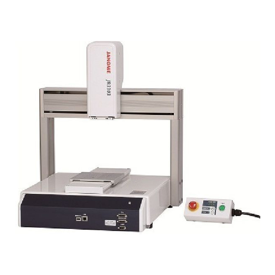
1. SYSTEM CONFIGURATION Teaching Pendant (Optional) Robot Example: JR3203N-BC Switchbox (Switchbox specification robots only) with a Windows® 7 / 8 / 8.1 operating system Tool* Dispenser, Electric Screwdriver, etc. PLC, etc. Area Sensor, etc. * RS-232C Windows is a registered trademark of Microsoft Cable* Not included An RS-232C port on the back of the robot is optional... -
Page 15: Installation
2. INSTALLATION Danger Do not use where flammable or corrosive gas is present. Leaked gas accumulating around the unit causes explosions and fire. Warning Make sure that you securely install the unit in a place that can fully withstand both the unit’s weight and its usage. Install the robot and switchbox on a workbench 60cm or higher above floor level, and install the robot in the center of the workbench. -
Page 16: Common To The Jr3200 Series
2.1 Common to the JR3200 Series NOTE When installing, rotate the rubber feet to adjust the height. Be sure to make them stable. Example: JR3203N-AC -φ (Rubber Feet) 4-M8 There are four rubber feet (ϕ30). The values within the brackets above are for reference only. -
Page 17: Common To The Jr3300 Series
2.2 Common to the JR3300 Series Example: JR3303N-AC -φ (Rubber Feet) 4-M8 (15.5) There are four rubber feet (ϕ27). NOTE • The robot may rattle depending on the tool mass. If so, be sure to secure the unit. To secure the unit, remove the rubber feet and use the 4 M8 screw holes used for fastening the rubber feet, with spacers of a height of 20mm or more (due to protrusions). -
Page 18: Common To The Jr3400 Series
2.3 Common to the JR3400 Series Example: JR3403N-AC 4-φ27 (Rubber Feet) 4-M8 (15.5) There are four rubber feet (ϕ27). NOTE • The robot may rattle depending on the tool mass. If so, be sure to secure the unit. To secure the unit, remove the rubber feet and use the 4 M8 screw holes used for fastening the rubber feet with spacers of a height of 20mm or more (due to protrusions). -
Page 19: Teaching Pendant Hanging Ring
2.4 Teaching Pendant Hanging Ring You can attach the hanging ring included in the package to the teaching pendant to hang it up. Also, if you are using the teaching pendant as a monitor during use in Run Mode, install at an easy to operate height of 60cm or higher from the ground. -
Page 20: Cable Connection
2.5 Cable Connection 2.5.1 JR3200 Series Installed Switch Specifications Front View (Example: JR3203N-AC) Fieldbus * (optional) Screw Holes Teaching Pendant MEMORY COM1: RS-232C Screw Holes FB Cover For models equipped with a Fieldbus (DeviceNet, CC-Link only), attach the included FB Cover to the main unit with the screws included to protect the terminal. - Page 21 Rear View (Example: JR3203N-AC/BC) COM2: RS-232C (optional) COM3: RS-232C (optional) I/O-SYS I/O-1 or I/O-MT(optional) Area Sensor etc. I/O-S (optional) I/O-S Connector (optional) INLET Power Cord If you do not connect a safety device such as an area sensor* , connect the included I/O-S connector* with the two lead wires short circuited.
-
Page 22: Jr3300 Series
2.5.2 JR3300 Series Installed Switch Specifications Front View (Example: JR3303N-AC) Teaching Pendant MEMORY COM1: RS-232C Switchbox Specifications Front View (Example: JR3303N-BC) Switchbox Install the switch box 60cm or higher from the floor and at a height convenient for operation. Setup Desktop Robot JR3000... - Page 23 Rear View (Example: JR3303N- AC/BC) I/O-MT (optional) COM2: RS-232C (optional) COM3: RS-232C (optional) Screw Holes I/O-SYS I/O-1 (optional) Screw Fieldbus * Holes (optional) FB Cover Area Sensor I/O-S (optional) I/O-S Connector (optional) OUTLET (Depending on the specs, the robot may or may not have an outlet and the shape may vary.) INLET...
-
Page 24: Jr3400 Series
2.5.3 JR3400 Series Installed Switch Specifications Front View (Example: JR3403N-AC) Teaching Pendant MEMORY COM1: RS-232C Installed Switchbox Specifications Front View (Example: JR3403N-BC) Switchbox Install the switch box 60cm or higher from the floor and at a height convenient for operation. Setup Desktop Robot JR3000... - Page 25 Rear View (Example: JR3403N-AC/BC) I/O-MT (optional) COM2: RS-232C (optional) COM3: RS-232C (optional) Screw Holes I/O-SYS I/O-1 (optional) Screw Holes Fieldbus * (optional) FB Cover I/O-S (optional) Area Sensor I/O-S Connector (optional) OUTLET (Depending on specs the robot may or may not have an outlet and the shape may vary) INLET Power Cord...
- Page 26 2.5.4 Device Connections For information regarding connecting an external device via I/O-SYS refer to the operation manual External Control (IO/Fieldbus), for LAN connections refer to “2.6 Connecting to a PC (Ethernet)” and for all other connections refer to the operation manual Specifications. Connector Mark Connecting Cable Connecting Device...
-
Page 27: Protective Grounding
COMPATIBILITY WITH EC DIRECTIVES This robot is a semi-finished product, and includes a declaration to the EC directive. Janome implements its conformity testing via a third-party certification for each of the EMC, LCD, MD directives. Attention The applicable requirements of the MD and EMC Directives vary depending on the machine settings and systems. -
Page 28: Attaching Devices
2.5.6 Attaching Devices Tie up air tubes and cables using the path illustrated below as a reference. NOTE Make sure that each cable does not interfere with robot movements. Cable Tie (included) Cord Clamp Bundle and tie up the air (included) tubes, cords and cables with the cable ties. -
Page 29: Connecting To A Pc (Ethernet)
2.6 Connecting to a PC (Ethernet) To back up the robot’s C&T data and to upgrade the robot’s system software, connect the robot and a PC via Ethernet and make sure the PC and robot are able to interface. Ethernet Overview The robot is fitted with an Ethernet connector (10/100BASE-TX) by standard. -
Page 30: Jr C-Points Ii Limited Edition Requirements
2.6.1 JR C-Points II Limited Edition Requirements To operate JR C-Points II Limited Edition (included in the Operation Manual CD), the following system configurations are necessary: Computer A PC capable of running Windows® 7/8/8.1 Memory capacity 512MB or more Microsoft Windows® 7/8/8.1 NOTE: compatible with both 32bit/64bit systems. -
Page 31: Lan Cable
2.6.2 LAN Cable Make sure power to both the robot and the PC are OFF before attaching or Attention removing cables. Failure to do so can cause malfunction. Use a straight LAN cable (category 5) compatible with the 10/100BASE-TX standard to connect the Robot and PC. -
Page 32: Lan Port
2.6.3 LAN Port Diagram: RJ-45 LAN Port Pin Assignment Pin No. Name Function Transmit signal+ Transmit signal- Receive signal+ Not connected Not connected Receive signal- Not connected Not connected 2.6.4 Communication Settings (IP Address Settings) Ethernet communication uses “TCP/IP protocol”. For this reason, you need to set the IP address, subnet mask, and default gateway as preparations for Ethernet connection. -
Page 33: Robot Ip Address Settings
2.6.5 Robot IP Address Settings You can set up the robot’s IP address from the PC software JR C-Points II (optional). (This is also possible with Limited Edition) Open the JR C-Points II robot IP address settings dialog by clicking [Robot] [IP-Address Settings]. -
Page 34: Backing Up And Restoring Robot Data
3. BACKING UP AND RESTORING ROBOT DATA The robot (data) storage area is partitioned as shown by the Robot System diagram on the right. All of the storage area partitions, Software including the robot system software storage partition, are subject to backup and data restoration operations. Individual Configuration Info. -
Page 35: Restore Data
3.2 Restore Data This restores robot data using the data saved in [Robot Data Backup]. Restoring robot data deletes all of the data in the robot (robot system software, C&T data, individual configuration information and model setting files) and overwrites it with the data in the backup file. Click [Robot] on the menu bar and select [Restore Robot Data] from the pull-down menu. -
Page 36: Sending And Receiving C&T Data
4. SENDING AND RECEIVING C&T DATA The data sent and received between the robot and the PC is teaching data and customizing data, sent as one unit (C&T data). NOTE To create backup data using a PC, refer to “2.6 Connecting to a PC (Ethernet)” in this manual, and “2.2 Connecting to a PC (LAN Connection)”... - Page 37 Have the robot doing one of the following: Switch Run Mode: Waiting for run start (Wait Start Point) External Run Mode: Waiting for run start (Wait Start Point) Teaching Mode: Point value setting screen Startup JR C-Points II Limited Edition, and from the [Robot] pull down menu select [Receive C&T Data].
-
Page 38: Transmitting Robot System Software
5. TRANSMITTING ROBOT SYSTEM SOFTWARE This robot is controlled by built-in robot system software. To upgrade the robot system software or make a system recovery due to the robot not starting up properly, follow the instructions below. (The robot system software version number can be confirmed through the version information display described in “10. - Page 39 NOTE • To perform this operation, the robot and PC must be connected. Refer to “2.6 Connecting to a PC (Ethernet)” and make sure the robot and PC can interface. • If you are using JR C-Points II software (optional), the robot system software can also be upgraded by selecting [Send Robot System Software] from the [Robot] pull-down menu.
-
Page 40: Clock Settings
6. CLOCK SETTINGS Before you first use the robot, set up the clock settings. Once you set up clock settings, the robot can record the date and time of when errors occur. You can set this with the teaching pendant or PC software (optional). For setting up clock settings via the teaching pendant, press the MODE key and switch over to the Administration Mode. -
Page 41: Settings Needed For Teaching
7. SETTINGS NEEDED FOR TEACHING Before registering a program etc. matchup the following settings to the methods and environment with which you will use the robot. 7.1 3-Axis Specifications: Tool Data The following settings are in [Tool Data]: • Tool Mass (the mass affecting the Y axis) •... -
Page 42: Axis Specifications: Tool Data
TCP-∆Z After changing tools etc., if the tool height is different from the registered tool center point position, enter the Z-direction difference to TCP-∆Z. NOTE: When adding a new program, the values of the default all program common settings (customizing data) are entered as program data default values. Additionally, when using the additional function data [Tool Data], you can change tool data at intervals between specific points. - Page 43 TCP-X, TCP-Y The TCP (tool center point) is the X and Y TCP-X direction distance from the R axis center to the Top View tool tip. With [Direct TCP-XY Setting], automatically calculate and set the [TCP-X] and TCP-Y [TCP-Y] values by indicating the same point twice with the tool tip (from different R-axis angles).
-
Page 44: Workpiece Mass
7.3 Workpiece Mass There is no [Workpiece Mass] setting for the JR3200. This is fixed at 7kg. For other models, the default for [Workpiece Mass] is 5kg. NOTE With the PC software (JR C-Points II) this item is not available and cannot be modified. Set [Workpiece Mass] using the table below. -
Page 45: Settings Needed To Make A Run
8. SETTINGS NEEDED TO MAKE A RUN Before running a point or program, match up the following settings to the methods and environment with which you will use the robot. 8.1 External Run Mode Settings If using the robot in External Run Mode, set the source from where the entered start signal becomes valid. -
Page 46: Setting Program Numbers
• Ethernet Send a run start command via Ethernet and the run starts. The receiving port on the robot side is 10031. For further information regarding commands, refer to Communication Control (COM/LAN). 8.2 Setting Program Numbers Here you can set the method for changing program numbers. 8.2.1 Changing Program Numbers To change program numbers, there are 5 methods shown below. -
Page 47: Program Number Switching Method
MENU [All Program Common Settings] [I/O Settings] [Program Number Reading Format] [Data] [All Program Common Settings] [Common Data] 8.2.3 Program Number Switching Method If you want to change program numbers by connecting a digit switch to the I/O terminal, select [Load at Start]. -
Page 48: I/O-S Settings (Optional)
8.3 I/O-S Settings (Optional) The I/O-S is a connector intended for use with an area sensor or a light curtain etc. If the signal from this connector comes ON during a run, the robot makes an emergency stop. It is possible to restrict the emergency stop so it does not occur if the I/O-S signal comes ON when the robot is in standby. -
Page 49: Converting Jr2000/Jr2000N Data To Jr3000 Data
9. CONVERTING JR2000/JR2000N DATA TO JR3000 DATA To use JR2000/JR2000N series teaching data as JR3000 series C&T data, it is necessary to convert the data. The following three steps are needed to convert data: 1. Use JR Points (JR2000 optional) and/or JR C-Points (JR2000N optional) to send the data to the 2. - Page 50 Please carry out the following: (This is done using a PC with JR-Points or JR C-Points and JR C-Points II installed and connected to both the JR2000/JR2000N and JR3000 Series robots.) 1. Turn ON the robot and the PC. If the robot is in Run Mode, make sure it is in run standby. For other modes, have the robot at the base screen.
- Page 51 Precautions when converting from JR-Points to JR C-Points II • The sysFlag numbers for point jobs, execute conditions, PLC programs etc., do not change when they are converted over from JR-Points, however, contents of some items have changed with JR C-Points II. Please confirm after converting over to JR C-Points II. Precautions when converting from JR C-Points to JR C-Points II •...
- Page 52 No part of this manual may be reproduced in any form, including photocopying, reprinting, or translation into another language, without the prior written consent of JANOME. ©2014, Janome Sewing Machine Co., Ltd., All rights reserved.