Table of Contents
Advertisement
SLV-ED225/ED323/ED825/ED828/ED925/ED929/
SERVICE MANUAL
System
Colour system
ED225/ED323/ED825/ED828/ED925/ED929:
PAL, MESECAM, NTSC 3.58, NTSC 4.43
EZ727: PAL, NTSC 3.58, NTSC 4.43
EZ121/EZ424/EZ725: PAL, NTSC 4.43
TV system
ED929: B/G, D/K, I, NTSC-M
ED225/ED323/ED825/ED828/ED925: B/G, D/K, I
EZ121/EZ424/EZ725/EZ727: B/G, B/B
Channel coverage
B/G: VHF E2 to E12/UHF E21 to E69/CATV S01 to
S05, S1 to S41
B/B: VHF R1 to R12/UHF R21 to R69
D/K: VHF R1 to R12/UHF R21 to R69
I: VHF SA4 to SA13/UHF B21 to B69/CATV S01
to S05,S1 to S41
RF output signal
UHF channels 21 to 69 (G, I, K, B, M)
UHF channels 28 to 69 (B/B)
Aerial out
75-ohm asymmetrical aerial socket
EZ121/EZ424/EZ725/EZ727
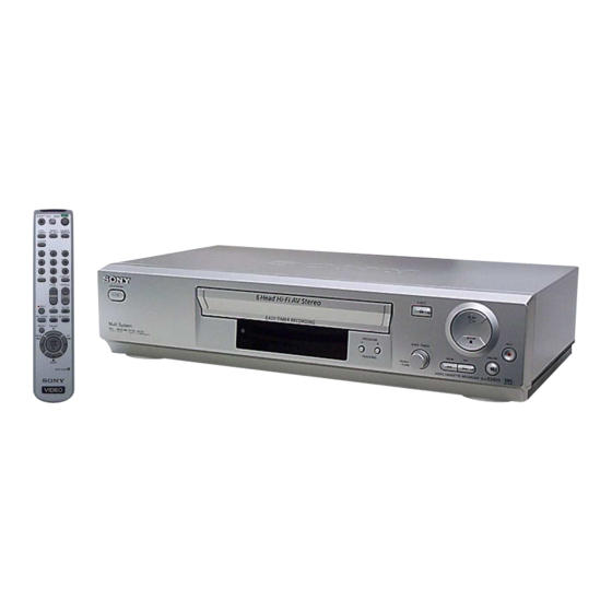
Photo: SLV-ED825PS
RMT-V408
SPECIFICATIONS
Tape speed
ED929:
SP: PAL
23.39 mm/s (recording/playback)
NTSC 33.35 mm/s (recording/playback)
LP: PAL
11.70 mm/s (recording/playback)
NTSC 16.67 mm/s (playback only)
EP: NTSC 11.12 mm/s (recording/playback)
ED225/ED323/ED825/ED828/ED925/EZ727:
SP: PAL
23.39 mm/s (recording/playback)
NTSC 33.35 mm/s (recording (Line input only)/
playback)
LP: PAL
11.70 mm/s (recording/playback)
NTSC 16.67 mm/s (playback only)
EP: NTSC 11.12 mm/s (recording (Line input only)/
playback)
EZ121/EZ424/EZ725:
SP: PAL
23.39 mm/s (recording/playback)
NTSC 33.35 mm/s (playback only)
LP: PAL
11.70 mm/s (recording/playback)
NTSC 16.67 mm/s (playback only)
EP: NTSC 11.12 mm/s (playback only)
Maximum recording/playback time
10 hrs. in LP mode (with E300 tape)
Rewind time
Approx. 1 min.(with E180 tape)
RMT-V408/V408A/V409
Middle East Model
SLV-ED323ME/ED323SG/ED828ME/ED828SG
SLV-ED225PS/ED825PS/ED925PS
Hong Kong Model
Australia Model
Refer to the SERVICE MANUAL of VHS MECHANI-
CAL ADJUSTMENT MANUAL VII for MECHANICAL
ADJUSTMENTS. (9-921-790-11)
Inputs and outputs
LINE IN 1/LINE-2 IN
VIDEO IN, phono jack (1)
Input signal: 1 Vp-p, 75 ohms,
unbalanced, sync negative
AUDIO IN, phono jack (2)
Input level: 327 mVrms
Input impedance: more than 47 kilohms
General
Power requirements
ED225/ED323/ED825/ED828/ED925/ED929:
110 – 240 V AC, 50/60 Hz
EZ121/EZ424/EZ725/EZ727:
220 – 240 V AC, 50 Hz
Power consumption
ED225/ED323/EZ121/EZ424: 15 W
ED825/ED828/ED925/ED929/EZ725/EZ727: 17 W
3 W (POWER SAVE is set to ON, minimum)
Operating temperature
5 °C to 40 °C
Storage temperature
–20 °C to 60 °C
VIDEO CASSETTE RECORDER
E Model
SLV-ED929MI
SLV-EZ121AZ/EZ424AZ/
EZ725AZ/EZ727AZ
TS-10 MECHANISM
— Continued on next page —
Advertisement
Table of Contents

Related Manuals for Sony SLV-ED225


Summary of Contents for Sony SLV-ED225
- Page 1 SLV-ED225/ED323/ED825/ED828/ED925/ED929/ EZ121/EZ424/EZ725/EZ727 RMT-V408/V408A/V409 SERVICE MANUAL Middle East Model SLV-ED323ME/ED323SG/ED828ME/ED828SG E Model SLV-ED225PS/ED825PS/ED925PS Hong Kong Model SLV-ED929MI Australia Model SLV-EZ121AZ/EZ424AZ/ EZ725AZ/EZ727AZ Photo: SLV-ED825PS TS-10 MECHANISM RMT-V408 Refer to the SERVICE MANUAL of VHS MECHANI- CAL ADJUSTMENT MANUAL VII for MECHANICAL ADJUSTMENTS. (9-921-790-11)
-
Page 2: Ez121/Ez424) ··································································
LINE WITH MARK 0 ON THE SCHEMATIC DIAGRAMS AND IN THE PARTS LIST ARE CRITICAL TO SAFE OPERATION. REPLACE THESE COMPONENTS WITH SONY PARTS WHOSE PART NUMBERS APPEAR AS SHOWN IN THIS MANUAL OR IN SUPPLEMENTS PUBLISHED BY SONY. — 2 —... -
Page 3: Table Of Contents
TABLE OF CONTENTS Important Service Guide P.C.Boards Mode Switch (Program Switch) Assembly Point ························· 4 Main PCB (AUS) ································································ 3-3 How to eject the cassette tape Main PCB (E, HK, ME) ····················································· 3-7 (If the unit does not operate on condition that tape is inserted Function PCB (Hi-Fi model) ············································... -
Page 4: Important Service Guide
IMPORTANT SERVICE GUIDE MODE SWITCH (PROGRAM SWITCH) ASSEMBLY POINT 1) When installing the ass’y deck on the Main PCB, be sure to align the assembly point of mode switch. ASSEMBLY POINT (ALIGN TWO ARROWS) Fig. 1 HOW TO EJECT THE CASSETTE TAPE (If the unit does not operate on condition that tape is inserted into housing ass’y) 1) Turn the Gear Worm 1 clockwise in the direction of arrow with screw driver. -
Page 5: General
SLV-ED225/ED323/ED825/ED828/ED925/ED929/ EZ121/EZ424/EZ725/EZ727 1. GENERAL This section is extracted from SLV-ED929MI/ED925PS/ED828ME/ED828SG/ ED825PS/ED323ME/ED323SG/ED225PS instruction manual. (3-073-156-11) Getting Started For SLV-ED323ME/SG and ED225PS Index to parts and controls Refer to the pages indicated in parentheses ( ) for details. Front panel For SLV-ED929MI, ED925PS, ED828ME/SG and ED825PS... -
Page 6: Step 1 : Unpacking
Using the remote Remote sensor commander You can use this remote commander to operate this VCR and a Sony TV. Buttons on the remote commander marked with a dot (¥) can be Check your model name used to operate your Sony TV. -
Page 7: Step 3 : Connecting The Vcr
¥ Do not use a new battery together with an old one. TV using an audio/video cable to get a better picture and sound. ¥ Do not use different types of batteries together. ¥ Some buttons may not work with certain Sony TVs. Connecting the aerial Mains lead... -
Page 8: Step 5 : Setting The Clock
Step 4 : Setting up the VCR with the Auto Set Up function (continued) To cancel the Auto Set Up function Press MENU. To change the RF channel Press OK. If the picture does not appear clearly on the TV, change the RF channel on PLAY The SYSTEM SELECT menu appears. -
Page 9: Step 6 : Selecting The Tv System
Step 6 : Selecting the TV system Selecting a language (SLV-ED828ME/SG and ED323ME/SG only) You must select the appropriate TV system for your area. You can change the on-screen display language from the one you selected with the Before you start Auto Set Up function. -
Page 10: Changing/Disabling Programme Positions
Presetting channels (continued) Changing/disabling programme If the picture is not clear positions If the picture is not clear, you may use the Manual Fine Tuning (MFT) function. After step 4, press M/m to select MFT. Press </, to get a clear After setting the channels, you can change the programme positions as you like. -
Page 11: Basic Operations
Changing/disabling programme positions (continued) Enter the station name. MANUA L T UNING 1 Press M/m to select a character. PLAY Changing the station names SYS TEM : B / G/ D/ K Each time you press M, the You can change or enter the station names (up to 4 characters). 0 3 3 character changes as shown —... -
Page 12: Recording Tv Programmes
Press z REC to start recording. Recording TV programmes The recording indicator lights up red in the display window. Before you start... ¥ Refer to Index to parts and controls for button locations. Turn on your TV and set it to the video channel. Insert a tape with its safety tab in place. -
Page 13: Recording Tv Programmes Using The Easy Timer
Recording TV programmes using the Press EASY TIMER. EASY TIMER START indicator and the current time appear in the display Easy Timer window. The Easy Timer function allows you to ?/1 ON/STANDBY EASY TIMER x STOP make timer recordings of programmes without turning on your TV. -
Page 14: Recording Tv Programmes Using The G-Code System
Recording TV programmes using the Easy Timer (continued) About the Demonstration Mode The Easy Timer function has a Demonstration Mode that allows the user, such as a salesperson, to enter more than eight examples of timer settings when demonstrating To set the clock the use of the Easy Timer. -
Page 15: Recording Tv Programmes Using The Timer
Recording TV programmes using the G-CODE system (SLV-ED929MI ¤ Recording TV programmes using the only) (continued) Daily/weekly recording timer In step 4 above, press m to select the recording pattern. Each time you press m, the indication changes as shown below. Press M to change the indication You can preset a total of eight programmes, including settings made with other timer in reverse order. -
Page 16: Additional Operations
Additional Operations Playing/searching at various speeds Setting the recording duration time After you have started recording in the normal way, you can have the VCR stop Before you start recording automatically after a specified duration. ¥ Refer to Index to parts and controls for button locations. Before you start Playback options Operation... -
Page 17: Recording Stereo And Bilingual Programmes
In the NICAM system (SLV-ED929MI and ED925PS only) Recording stereo and bilingual This VCR receives and records stereo and bilingual programmes based on the NICAM system (NICAM appears on the TV screen). When a stereo or programmes (not available on SLV- bilingual programme is received, the STEREO indicator appears in the display window. -
Page 18: Adjusting The Picture
Adjusting the picture Reducing the VCR’s power consumption Adjusting the tracking You can turn off the indicators in the display window when the VCR is off (standby Although the VCR automatically adjusts the mode) to reduce the VCR’s power consumption. tracking when playing a tape, distortion may occur if the recording is in poor condition. -
Page 19: Editing
Do not use a commercially available liquid type cleaning cassette other than Sony s, as it may damage the video heads. ¥ The video heads may have to be replaced. Consult your local Sony service facility for more information. -
Page 20: Index
¥ The video heads are dirty. Clean the video heads ¥ Turn the power off and unplug the mains lead. in stereo or the STEREO using the Sony T-25CLD, E-25CLDR, or T-25CLW A tape cannot be inserted. ¥ Check that a tape is not already in the tape indicator in the display video head cleaning cassette as explained above. -
Page 21: Disassembly
SLV-ED225/ED323/ED825/ED828/ED925/ED929/ EZ121/EZ424/EZ725/EZ727 2. DISASSEMBLY 2-1 MONO MODELS 2-1-1 CASE UPPER Case upper 1 Two screws 2 Lift up the cabinet top in the direction of arrow by releasing the hook. Fig. 2-1 Cabinet Top 2-1-2 COVER BOTTOM 1 Release two snapfits 2 Lift up the bottom cover in the direction of arrow. -
Page 22: Ass'y-Panel Front
2-1-3 ASS’Y-PANEL FRONT 2 Release three hooks 1 Release four hooks ASS'Y-PANEL FRONT – BOTTOM VIEW – – TOP VIEW – Fig. 2-3 Ass’y-Panel Front... -
Page 23: Ass'y Main Board, Deck
2-1-4 ASS’Y MAIN BOARD, DECK 3 Four screws 4 Flat cable 5 Flat cable 8 Ass'y-deck 6 Flat cable 1 Two screws 9 Main board 7 Release hook PUSH 2 Bracket-frame Fig. 2-4 Ass’y Main-PCB, Deck... -
Page 24: Hi-Fi Models
2-2 Hi-Fi MODELS 2-2-1 CASE UPPER Case upper 1 Two screws 2 Lift up the cabinet top in the direction of arrow by releasing the hook. Fig. 2-5 Cabinet Top 2-2-2 COVER BOTTOM 1 Release two snapfits 2 Lift up the bottom cover in the direction of arrow. Fig. -
Page 25: Ass'y-Panel Front
2-2-3 ASS’Y-PANEL FRONT 2 Release three hooks 1 Release four hooks ASS'Y-PANEL FRONT – BOTTOM VIEW – – TOP VIEW – Fig. 2-7 Ass’y-Panel Front 2-2-4 JACK BOARD Disconnect the CN701 from the ass'y main and then lift the jack board up. CN702 CN704 CN705... -
Page 26: Deck, Main Board
2-2-5 DECK, MAIN BOARD 3 Four screws 4 Flat cable 5 Flat cable 8 Ass'y-deck 6 Flat cable 1 Two screws 9 Main board 7 Release one tab 2 Bracket-frame Fig. 2-9 Ass’y Main-PCB, Deck 2-6E... -
Page 27: P.c.boards
SLV-ED225/ED323/ED825/ED828/ED925/ED929/ EZ121/EZ424/EZ725/EZ727 3. P.C.BOARDS 3-1 Main PCB (AUS) - - - - - - - - - - - - - - - - - - - - - - - - - - - - - - - - - - - - - - - - - - 3-3... -
Page 28: Main Pcb (Aus)
3-1 MAIN PCB (AUS) COMPONENT SIDE... - Page 29 CONDUCTOR SIDE...
-
Page 30: Main Pcb (E, Hk, Me)
3-2 MAIN PCB (E, HK, ME) COMPONENT SIDE... - Page 31 CONDUCTOR SIDE 3-10...
-
Page 32: Function Pcb (Hi-Fi Model)
3-3 FUNCTION PCB (Hi-Fi MODEL) COMPONENT SIDE CONDUCTOR SIDE 3-11 3-12E... -
Page 33: Schematic Diagrams
SLV-ED225/ED323/ED825/ED828/ED925/ED929/ EZ121/EZ424/EZ725/EZ727 4. SCHEMATIC DIAGRAMS Block Identification of Main PCB - - - - - - - - - - - - - - - - - - - - - - - - - - - - - - - - 4-3 4-1 S.M.P.S. -
Page 34: Block Identification Of Main Pcb
BLOCK IDENTIFICATION OF MAIN PCB Component Side Conductor Side... -
Page 35: Aus)
4-1 S.M.P.S. (AUS) PWR OFF PWR ON... -
Page 36: E, Hk, Me)
4-2 S.M.P.S. (E, HK, ME) PWR OFF PWR ON... -
Page 37: Power
4-3 POWER 4-10... -
Page 38: System Control/Servo
4-4 SYSTEM CONTROL/SERVO 4-11 4-12... -
Page 39: Audio/Video
4-5 AUDIO/VIDEO - - - - - VIDEO SIGNAL IN/OUT LUMINANCE RECORDING - - - - - LUMINANACE PLAYBACK CHROMA RECORDING - - - - - CHROMA PLAYBACK AUDIO PROCESS IN - - - - - AUDIO PROCESS OUT 4-13 4-14... -
Page 40: Hi-Fi (Hi-Fi Model)
4-6 Hi-Fi (Hi-Fi MODEL) - - - - - AUDIO PB PROCESS - - - - - AUDIO REC PROCESS AUDIO PROCESS (IN) - - - - - AUDIO PROCESS (OUT) C R IN AUX R IN AV R IN (MTS MODEL : 43K) TU L IN TU L IN... -
Page 41: Tm-Block
4-7 TM-BLOCK - - - - - VIDEO PROCESS (IN) - - - - - VIDEO PROCESS (OUT) AUDIO PROCESS (IN) - - - - - AUDIO PROCESS (OUT) 4-17 4-18... -
Page 42: Osd/Vps/Pdc
4-8 OSD/VPS/PDC - - - - - OSD VIDEO PROCESS (IN) - - - - - OSD VIDEO PROCESS (OUT) 4-19 4-20... -
Page 43: A2/Nicam (Ed925/Ed929/Ez725/Ez727)
4-9 A2/NICAM (ED925/ED929/EZ725/EZ727) 4-21 4-22... -
Page 44: Input-Output (Rca Jack)
4-10 INPUT-OUTPUT (RCA JACK) AUDIO PROCESS (OUT) - - - - - AUDIO PROCESS (IN) VIDEO PROCESS (OUT) - - - - - VIDEO PROCESS (IN) 4-23 4-24... -
Page 45: Sub (Hi-Fi Model)
4-11 SUB (Hi-Fi MODEL) 4-25 4-26... - Page 46 S.M.P.S. BLOCK SYSTEM CONTROL/SERVO BLOCK AUDIO/VIDEO BLOCK TM BLOCK O. S. D. BLOCK 1 Q1SR01-COLLECTOR 3 IC601-3 7 IC610-97 qa IC301-100 qf IC301-88 qj TM401-24 qk IC6P01-19 POWER OFF/380Vp-p PB/5.1Vp-p REC/1.5Vp-p REC(LP)/2.5Vp-p 0.9Vp-p 2.1Vp-p PB/5.1V 2 Q1SR01-COLLECTOR 4 IC601-9 8 TP601-89 qs IC301-65 qg IC301-94 POWER ON/400Vp-p...
- Page 47 OSD BLOCK LOGIC BLOCK AV BLOCK HI-FI BLOCK A2-NICAM BLOCK PLAY STOP PLAY STOP PLAY STOP PLAY STOP PLAY STOP PLAY STOP PLAY STOP PLAY STOP MODE MODE MODE MODE MODE MODE MODE MODE IC601 UPD784927GF IC601 UPD784927GF IC605 24LCXX IC301 LA71750M/LA71730M IC301...
- Page 48 MEMO 4-32E...
-
Page 49: Alignment And Adjustment
SLV-ED225/ED323/ED825/ED828/ED925/ED929/ EZ121/EZ424/EZ725/EZ727 5. ALIGNMENT AND ADJUSTMENT 5-1 REFERENCE 1) X-Point (Tracking center) adjustment, “Head switching adjustment” and “NVRAM option setting” can be adjusted with remote control. 2) When replacing the Micom (IC601) and NVRAM (IC605 ; EEPROM) be sure to adjust the “Head switching adjustment” and “NVRAM option setting”. -
Page 50: Test Point Location For Adjustment Mode Setting
5-1-2 Test point location for adjustment mode setting (EZ121/EZ424) PRESS Fig. 5-2 Main PCB (Top View) -
Page 51: Test Point Location For Adjustment Mode Setting
5-1-3 Test point location for adjustment mode setting (ED225/ED323) PRESS Fig. 5-3 Main PCB (Top View) -
Page 52: Sw7T21 (Test) Location For Adjustment Mode Setting
5-1-4 SW7T21 (TEST) location for adjustment mode setting (ED825/ED828/ED925/ED929/EZ725/EZ727) TEST (SW7T21) BUTTON Fig. 5-4 Function PCB (Top View) -
Page 53: Mechanical Adjustment
5-2 MECHANICAL ADJUSTMENT Note : Refer to the Mechanical Manual for the adjustment and confirmation of ass’y deck. 5-2-1 The number and position of test point Test point : TP602 (H’D S/W -Trigger) TP301 (Envelope) TP302 (Audio output) AUDIO OUTPUT ENVELOPE HEAD SWITCHING Fig. -
Page 54: Head Switching Point Adjustment
5-3 HEAD SWITCHING POINT ADJUSTMENT 1) Playback the alignment tape. 2) Press the “TEST” button on Main PCB/Function PCB to set the adjustment mode. (See Fig. 5-2, 5-3 and 5-4) 3) Press the “SP/LP” button of remote control then adjustment is operated automatically. (See Fig. 5-1) 4) Turn the Power off. -
Page 55: Repair Parts List
SLV-ED225/ED323/ED825/ED828/ED925/ED929/ EZ121/EZ424/EZ725/EZ727 6. REPAIR PARTS LIST Page 6-1 Exploded Views - - - - - - - - - - - - - - - - - - - - - - - - - - - - - - - - - - - - - - - - -... -
Page 56: Exploded Views
6-1 EXPLODED VIEWS NOTE: • -XX, -X mean standardized parts, so they may • The mechanical parts with no reference number The components identified by mark 0or have some differences from the original one. in the exploded views are not supplied. dotted line with mark 0 are critical for safety. -
Page 57: Instrument Assembly (Hi-Fi Model)
6-1-2 Instrument Assembly (Hi-Fi Models) supplied supplied not supplied not supplied not supplied not supplied not supplied supplied supplied not supplied Ref. No. Part No. Description Remarks Ref. No. Part No. Description Remarks 0 54 3-076-025-01 PANEL FRONT (ED825) 1-824-231-11 POWER CORD (EZ725/EZ727) 3-076-026-01 PANEL FRONT (ED828) 3-075-019-01 CASE UPPER 3-076-027-01 PANEL FRONT (EZ725) -
Page 58: Mechanical Parts (Top Side)
6-1-3 Mechanical Parts (Top Side) not supplied supplied supplied supplied not supplied supplied not supplied (OPTIONAL) supplied (OPTIONAL) not supplied not supplied supplied not supplied supplied Ref. No. Part No. Description Remarks Ref. No. Part No. Description Remarks 3-067-779-01 LEVER-GUIDE ASSY 1-804-710-11 DRUM ASSY (ED825/ED925/ED929/EZ725/EZ727) 3-067-780-01 SPRING-GUIDE 1-796-433-11 DAMPER-CAPSTAN... -
Page 59: Mechanical Parts (Bottom Side)
6-1-4 Mechanical Parts (Bottom Side) not supplied not supplied supplied not supplied supplied not supplied supplied not supplied not supplied Ref. No. Part No. Description Remarks Ref. No. Part No. Description Remarks 3-067-790-01 BELT-PULLEY 1-796-432-11 MOTOR-CAPSTAN... -
Page 60: Electrical Parts List
MAIN FUNCTION 6-2 ELECTRICAL PARTS LIST NOTE: • Items marked “*” are not stocked since they are • Abbreviation AUS : Australia model • Due to standardization, replacements in the seldom required for routine service. Some delay parts list may be different from the parts should be anticipated when ordering these items. - Page 61 MAIN Ref. No. Part No. Description Remarks Ref. No. Part No. Description Remarks C349 1-165-319-11 CERAMIC,CHIP 1000nF +80-20% 16V C350 1-115-339-11 CERAMIC,CHIP 100nF C501 1-126-109-11 ELECT 10uF C351 1-126-437-11 ELECT 47uF (Hi-Fi model) C352 1-126-458-61 ELECT C502 1-115-339-11 CERAMIC,CHIP 100nF (Hi-Fi model) C353 1-126-458-61 ELECT...
- Page 62 MAIN Ref. No. Part No. Description Remarks Ref. No. Part No. Description Remarks C651 1-163-033-11 CERAMIC,CHIP 22nF ZD1P04 1-804-417-11 DIODE MTZJ9.1B C655 1-163-121-11 CERAMIC,CHIP 0.15nF ZD1SS1 1-804-415-11 DIODE UZP43B (AUS) C679 1-163-033-11 CERAMIC,CHIP 22nF ZD801 1-804-803-11 DIODE MTZ6.2B (ED225) C680 1-126-926-11 ELECT 1000uF C692...
- Page 63 MAIN Ref. No. Part No. Description Remarks Ref. No. Part No. Description Remarks Q3A01 1-804-421-11 TRANSISTOR KSC945 R1SF19 1-247-831-11 CARBON 1/8W Q3A02 1-804-420-11 TRANSISTOR KSA733 (E, HK, ME) Q3A03 1-804-422-11 TRANSISTOR KTC3203-Y R1SF20 1-216-363-11 METAL OXIDE 0.33 Q3A04 1-804-422-11 TRANSISTOR KTC3203-Y (E, HK, ME) R1SF21 1-247-903-11 CARBON...
- Page 64 MAIN Ref. No. Part No. Description Remarks Ref. No. Part No. Description Remarks R4N03 1-216-627-11 RES-CHIP 1/10W R668 1-216-675-11 RES-CHIP 1/10W (ED925/ED929/EZ725/EZ727) R669 1-216-675-11 RES-CHIP 1/10W R4N04 1-216-661-11 RES-CHIP 1/10W R670 1-216-667-11 RES-CHIP 4.7K 1/10W (ED925/ED929/EZ725/EZ727) R502 1-216-670-11 RES-CHIP 6.2K 1/10W R671 1-216-667-11 RES-CHIP...
- Page 65 MAIN Ref. No. Part No. Description Remarks Ref. No. Part No. Description Remarks < MODULE > ACCESSORIES & PACKING MATERIALS RM701 1-477-308-11 MODULE REMOCON TSOP2238WE1 ******************************** < PHOTO TRANSISTOR > 1-477-367-11 REMOTE COMMANDER (RMT-V408) (ED225/ED323/EZ725/ED825/ED828/ED925/ S601 1-804-439-11 PHOTO TRANSISTOR EZ121) S602 1-804-439-11 PHOTO TRANSISTOR 1-477-368-11 REMOTE COMMANDER (RMT-V408A)
- Page 66 SLV-ED225/ED323/ED825/ED828/ED925/ED929/ EZ121/EZ424/EZ725/EZ727 Sony Corporation 2002D0500-1 Home Video Company 9-929-726-11 ©2002.4 — 88 — Published by Quality Assurance Dept.