Table of Contents
Advertisement
Quick Links
MARCH 2004
Terminal Server 16 - 37687
Terminal Server 8 - 37688
Rack Terminal Server 16 - 40870
Rack Terminal Server 8 - 40871
102 Terminal Server- 41872
104 Terminal Server - 41874
Terminal Server
User Guide
CUSTOMER
Order toll-free in the U.S 24 hours, 7 A.M. Monday to midnight Friday: 877-877-BBOX
SUPPORT
FREE technical support, 24 hours a day, 7 days a week: Call 724-746-5500 or fax 724-746-0746
INFORMATION
Mail order: Black Box Corporation, 1000 Park Drive, Lawrence, PA 15055-1018
Web site: www.blackbox.com * E-mail info@blackbox.com
Advertisement
Table of Contents

Related Manuals for Black Box 37687


Summary of Contents for Black Box 37687
-
Page 1: Terminal Server
Order toll-free in the U.S 24 hours, 7 A.M. Monday to midnight Friday: 877-877-BBOX SUPPORT FREE technical support, 24 hours a day, 7 days a week: Call 724-746-5500 or fax 724-746-0746 INFORMATION Mail order: Black Box Corporation, 1000 Park Drive, Lawrence, PA 15055-1018 Web site: www.blackbox.com * E-mail info@blackbox.com... - Page 2 Normas Oficiales Mexicanas (NOM) Electrical Safety Statement INSTRUCCIONES DE SEGURIDAD Todas las instrucciones de seguridad y operación deberán ser leídas antes de que el aparato eléctrico sea operado. Las instrucciones de seguridad y operación deberán ser guardadas para referencia futura. Todas las advertencias en el aparato eléctrico y en sus instrucciones de operación deben ser respetadas.
- Page 3 15. En caso de existir, una antena externa deberá ser localizada lejos de las lineas de energia. 16. El cable de corriente deberá ser desconectado del cuando el equipo no sea usado por un largo periodo de tiempo. 17. Cuidado debe ser tomado de tal manera que objectos liquidos no sean derramados sobre la cubierta u orificios de ventilación.
- Page 4 FEDERAL COMMUNICATIONS COMMISSION CANADIAN DEPARTMENT OF COMMUNICATIONS RADIO FREQUENCY INTERFERENCE STATEMENTS This equipment generates, uses, and can radiate radio frequency energy and if not installed and used properly, that is, in strict accordance with the manufacturer's instructions, may cause interference to radio communication. It has been tested and found to comply with the limits for a Class A computing device in accordance with the specifications in Subpart J of Part 15 of FCC rules, which are designed to provide reasonable protection against such interference when the equipment is operated in a...
-
Page 5: About This Manual
User Guide About this manual Purpose of this manual This manual tells you how to install, configure and use the Black Box Terminal Server communications servers. Who this manual is for This manual is aimed at users who want to connect serial devices directly to LANs and WANs. -
Page 6: Table Of Contents
Fast Contents ..................5 BOUT THIS MANUAL ..................... 6 ONTENTS ...................... 7 ONTENTS ................23 HAPTER NTRODUCTION ................32 HAPTER NSTALLATION ........... 50 HAPTER ERMINALS ON MUTLI USER SYSTEMS ..........58 HAPTER ETTING UP DIAL IN MODEM PORTS ........66 HAPTER ODEM AUTHENTICATION AND LOGGING ............. -
Page 7: Contents
Contents ............5 BOUT THIS MANUAL Purpose of this manual ..................5 Who this manual is for ...................5 ..............6 ONTENTS ................7 ONTENTS Page 7... - Page 8 HAPTER NTRODUCTION About the Terminal Server ................24 Terminal Server Features ................26 Hardware ....................26 Software ....................27 Security .....................28 Hardware Overview ..................29 Hardware description for Terminal Server ..........29 Hardware description for Rack Terminal Server ........30 Hardware description for 102/104 Terminal Server ........31 Page 8...
- Page 9 HAPTER NSTALLATION Connecting to your Network .................33 10BASE-T (twisted pair) ................33 10BASE2 (Thin Ethernet) .................33 AUI port.....................33 10/100BASE-T ..................33 Switching on Terminal Server ..............34 Communicating via ARP ................35 Communicating via a Terminal or PC ............36 The Menu System ...................37 Connections Menu ..................39 Administration Menu .................40 Server Configuration Menu ...............42 Port Setup Menu and Beyond..............44...
- Page 10 HAPTER ERMINALS ON MUTLI USER SYSTEMS Introduction ......................51 Terminal Port Configuration .................52 Host Table Setup .....................54 Making a Connection ..................55 Tips ........................57 Connecting via ‘fixed ttys’ .................57 Multisessions on terminals/PCs ..............57 Gateway Tables ..................57 Page 10...
- Page 11 HAPTER ETTING UP DIAL IN MODEM PORTS Introduction ......................59 Dial-in Port ......................60 The host ......................62 The modem ......................63 Client login .......................64 Tips ........................65 Domain Name Server (DNS) ..............65 WINS Server .....................65 MOTD .......................65 Gateway notes ..................65 Page 11...
- Page 12 HAPTER ODEM AUTHENTICATION AND LOGGING Introduction ......................67 User authentication/logging ................68 The host ......................71 Basic authentication..................71 User services authentication..............71 Logging ......................73 Tips ........................74 Page 12...
- Page 13 HAPTER IALOUT MODEM PORTS SETUP Introduction ......................76 Configuration ....................77 The host ......................78 For dial-out connections on Unix ..............78 For dial-out connections on Windows ® systems ........78 Routing ......................79 Remote Access Systems ................80 Dial-out PAP Authentication ..............82 Remote site devices ..................83 Tips ........................84 Page 13...
- Page 14 HAPTER MODEM IRTUAL MODEM About Vmodem (Virtual modem) ..............86 Configuring ports to use Vmodem ..............87 Configuring ports to use Vmodem in Normal Mode ........87 Making a Call using Vmodem in Normal Mode ..........89 Disconnecting a Call in Vmodem Normal Mode ..........89 Configuring Vmodem to use Dial on DTR mode........90 Making a Call using Vmodem in Dial on DTR Mode ........
- Page 15 HAPTER RINTING Introduction ......................95 Using ioland .....................96 Configuration.....................97 The Host ....................98 Using LPD ......................99 Configuration.....................99 Accessing the Printer ................101 LPD printing from DOS/Windows ® ............102 LPD Printing from BSD Unix and Linux ............103 LPD Printing from SYS V Unix..............104 LPD printing from AIX ................104 LPD printing from HP/UX ................104 Using RCP ......................105 Configuration.....................105...
- Page 16 HAPTER THER DEVICES SETUP Introduction ......................111 Reverse Telnet Port Configuration ..............112 The Host ....................113 Black Box IOLAND Utility ................114 Mandatory arguments ................115 Optional arguments...................116 Example daemon configuration file............119 Tips ........................120 Page 16...
- Page 17 10 T HAPTER HE MENU INTERFACE Introduction to menu commands ..............122 Toggle fields ....................122 Fast keys....................123 Connections menu ..................124 Port setup menu ....................126 Hardware ....................127 User ......................128 Flow control....................129 IP address....................130 Options......................131 Keys ......................132 Access ......................133 Administration menu ..................135 Extra statistics screens .................. 136 Access menu ....................137 Remote access sites.................138 Remote site devices..................140...
- Page 18 PPENDIX OMMAND NTERFACE Introduction ......................157 Using the CLI ....................158 System administration ...................159 Basic configuration ..................160 Command descriptions .................161 arp......................161 clear ......................161 connect .....................161 copy ......................162 dial ......................162 disconnect ....................162 exit ......................162 facreset .....................162 gateway.....................162 help ......................163 host ......................163 kill......................163 lock......................163 logout ......................163 prov ......................163 reboot......................164...
- Page 19 show ports ..................... 167 show lines ...................... 167 show statistics ....................167 su ......................167 telnet ......................167 test ......................168 Page 19...
- Page 20 B 48V DC R PPENDIX ERMINAL ERVER Introduction ......................170 Installing the Rack Terminal Server 48V DC ..........171 Installation....................171 Electrical Supply Details ................171 Safety Earth ....................172 Fusing .......................172 Electrical Safety Guidelines ................173 Connecting up your Rack Terminal Server ..........173 Disconnecting your Rack Terminal Server ..........173 Page 20...
- Page 21 PPENDIX ROUBLESHOOTING Introduction ......................175 Terminals/PC Problems .................176 Printer Problems .....................178 Modem problems ....................180 Unit still does not communicate ..............181 Resetting Your unit ..................182 Using the Statistics screens .................183 ETH/TTY/GATEWAY.................183 IP/ICMP/UDP ....................184 TCP......................184 Users......................184 Framed Link Status ...................185 Netstat.......................186 Gateway....................186 SLIP ......................186 Clear counters...................186 Restore counters..................187 Port Status ....................187...
- Page 22 PPENDIX ABLING Introduction ......................194 Serial port connectors on the Terminal Server unit .........195 Serial port connector guide ...............195 RS232 DB25 female DTE .................195 RS232 RJ45 DTE socket ................197 RS422 RJ45 DTE socket ................198 Standard modem cables ................199 Terminal Server DB25 DTE to Modem DB25 DCE ........199 Cable diagram ....................
-
Page 23: Chapter 1 Introduction
You need to read this chapter if you want an overview of the Terminal Server product. this chapter if you want to... This chapter provides introductory information about the Black Box Terminal Server, its associated components, software and configuration utilities. This chapter includes the following sections;... -
Page 24: About The Terminal Server
About the Terminal Server The Terminal Server is a unique Ethernet TCP/IP communications / terminal server allowing serial devices to be connected directly to LANs and WANs. The 2, 4, 8 or 16 serial ports enable Terminal Server to connect to a wide range of devices including: •... - Page 25 This configuration diagram shows many of the features available on the Ter- minal Server communications server: N E T 3 2 4 Terminal Server User Guide Chapter 1 Introduction About the Terminal Server Page 25...
-
Page 26: Terminal Server Features
Terminal Server Features Terminal Server RS-232 or RS-422 ports for is a TCP/IP communications server with 2, 4, 8 or 16, making serial network connections. It attaches to your TCP/IP network and allows serial devices such as modems, terminals and printers to access the network. Hardware Terminal Server hardware features include:... -
Page 27: Software
Software Terminal Server software features include: • Support for TCP/IP and UDP protocols including telnet and rlogin. • Remote access support including PPP, SLIP and CSLIP. • Printer support via lpd, rcp, and utilities. • Modem support via PPP and utilities. •... -
Page 28: Security
Security Terminal Server security features include: • Supervisory and port password. • Port locking. • Authentication with PAP support. • Per user access level assignment. • Service logging. • Logging facility for audit and billing. • Modem auto reset. Terminal Server User Guide Chapter 1 Introduction Terminal Server Features Page 28... -
Page 29: Hardware Overview
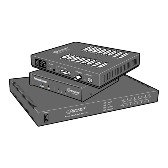
Hardware Overview The following table and diagrams describe the units: Model Type No. Ports Connector Interface 102/104 Terminal Table Top RJ45 RS-232 Server Terminal Server Table Top 8,16 DB25 RS232 Rack Terminal Server Rack Mount 4, 8, 16 RJ45 RS-232 Model Hardware description for Terminal Server 100 BASE T Link/Activity... -
Page 30: Hardware Description For Rack Terminal Server
Hardware description for Rack Terminal Server POWER 10 BASE T 100 BASE T ACTIVITY Port activity indicator Main power switch Power input socket Serial ports 10/100 BASE T socket Terminal Server User Guide Chapter 1 Introduction Hardware description for Rack Terminal Server Page 30... -
Page 31: Hardware Description For 102/104 Terminal Server
Hardware description for 102/104 Terminal Server Network indicator Port activity indicators Power indicator Power input socket Serial ports 10/100 BASE-T socket Terminal Server User Guide Chapter 1 Introduction Hardware description for 102/104 Terminal Server Page 31... -
Page 32: Chapter 2 Installation
This chapter provides information about installing the Black Box Terminal Server including connecting to your network, configuring communications as well as information on the menu system and general tips. This chapter includes the following sections;... -
Page 33: Connecting To Your Network
Connecting to your Network First connect Terminal Server to a network then begin configuring the unit for your application. Additional information on configuring modems and printers follows. Terminal Server and Rack Terminal Server connect to your ethernet network via one of the following (depending on your hardware model): •... -
Page 34: Switching On Terminal Server
Switching on Terminal Server The Terminal Server power supply accepts input voltages in the range 110 to 240V AC, allowing it to be used world-wide. The 102/104 Terminal Server has an external power supply unit. After you connect your LAN interface, you can power up the unit. The green power indicator at the side (or front for rack and 102/104 units) should be lit. -
Page 35: Communicating Via Arp
Communicating via ARP Your Terminal Server supports the ‘Address Resolution Protocol’ (ARP). It allows you to temporarily connect to your Terminal Server to assign a permanent IP address. If you prefer to use a terminal or PC attached to Terminal Server see Communicating via a Terminal or on page 36. -
Page 36: Communicating Via A Terminal Or Pc
Communicating via a Terminal or PC You can connect to Terminal Server using a terminal or PC (with a terminal emulation package such as Hyperterm). 1. Connect a terminal or your PC to port 1. The Terminal Server serial ports are DTE type RS-232 ports. -
Page 37: The Menu System
The Menu System You should now be at the Command Line Interface (CLI) of the Terminal Server as designated by the local> prompt. If you would like to continue in CLI mode refer to Appendix A Command Line Interface, but we recommend the menu system. 1. - Page 38 The Connections Menu should now be displayed. This menu displays the current state of the four possible connections. There are no active connections. The firmware version of Terminal Server is located on the lower left hand portion. The wording ‘REMOTE-ADMIN’ in the upper right signifies you are remotely telneted into Terminal Server (and will read ‘Terminal: 1’...
-
Page 39: Connections Menu
Connections Menu Select connection '1’ on the Connections Menu and press the Enter key. The Commands pop-up menu is displayed. There are a number of options available from this menu. Before communication across the network can be established the Terminal Server must be assigned a network IP address. -
Page 40: Administration Menu
Administration Menu The top level Administration Menu appears as follows: 1. Select the Password field and press the Enter key. Use the factory default password here: this is iolan (no caps). Note: This password level will time-out in four minutes if there is no activity. This is for security reasons and will take you back to Administration Menu (view level). - Page 41 2. Select the server entry and press the Enter key. This takes you into the Server Configuration Menu. Terminal Server User Guide Chapter 2 Installation The Menu System Page 41...
-
Page 42: Server Configuration Menu
Server Configuration Menu There are a number of fields in the Server Configuration menu which are explained in Chapter 10 The menu interface. At this point proceed as follows; 1. Give the Terminal Server an IP address and a name. 2. - Page 43 4. Select the Save & Exit field and press the Enter key. Other options are Quit & Exit, which does not save the changes before exiting this menu, Values, which will display the optional values for this field if available, and Cancel, which will take you back to this screen for more editing.
-
Page 44: Port Setup Menu And Beyond
Port Setup Menu and Beyond Your communications server is now ready to configure for terminals on multi-user systems or modems, printers and other devices. The next sections deal with each of these. If you’ve got a good feel for the menu system, you should proceed to the section appropriate for your application. - Page 45 This menu is divided into the following sections: Menu option Description Hardware Defines port type and is used for setting up the hardware configuration of the modem, terminal, printer or PC session. This section is always used. User Defines various user parameters such as name and terminal type. Most fields are used in this section.
-
Page 46: Tips
Tips Copy Command The Terminal Server has a copy command that allows you to copy the setup of one port to another. You will need to get to the CLI (from the Connection menu) and use the following syntax. Note: To get back to the menu system once in the CLI, type set menu at the command line. - Page 47 hd is the home directory for specifying Terminal Server firmware (optional) bf is the name of Terminal Server firmware (optional) ip is the IP address you want to use Note This BOOTP implementation is a subset and not a full implementation of the RFC. Note The most common error is bad information in the /etc/bootptab file (recheck it).
-
Page 48: Saving And Downloading Configurations
Saving and downloading configurations It is possible to save the configuration of your Terminal Server. This is convenient for loading multiple communications servers with the same setup. It is also advisable as a backup method. If the boot file name has the extension “.cfg” (eg iolan.cfg), it will be loaded as a configuration file rather than a boot file. -
Page 49: Domain Name Server (Dns)
Terminal Server will now automatically download this configuration on reboot. Remember that whenever you change a setting on the unit, it will be overwritten the next time the unit is rebooted unless the new configuration is saved. Domain Name Server (DNS) Terminal Server can be configured to take advantage of your network’s Domain Name Server (DNS). -
Page 50: Chapter 3 Terminals On Mutli-User Systems
Terminal Server User Guide Chapter 3 Terminals on mutli-user systems You need to read You need to read this chapter if you want information on setting up a terminal for use with this chapter if you your Terminal Server product. want to... -
Page 51: Introduction
Introduction Terminal Server is used extensively for connecting terminals, printers and modems on multi- user Unix systems, especially in retail applications. These Unix systems include SCO Unix, IBM AIX, HP-UX, Data General’s DG/UX, etc. This chapter deals with terminals and/or PCs using emulation packages (such as Hyperterm). -
Page 52: Terminal Port Configuration
Terminal Port Configuration This is the setup for making a terminal connect to a designated Unix host login prompt automatically. The following fields are important: Menu option Description Access Set this field to Local. This tells the terminal server port to listen for data on the RS-232 side. - Page 53 Menu option Description Remote Port This corresponds to Telnet service on the remote host and must be set to the standard 23 (or 513 for rlogin). Monitor DSR You can set this field to Yes if you wire the terminal’s DTR signal pin 20 (DB25) to the Terminal Server's DSR signal pin 3 on the RJ45 connector ( see Appendix D Cabling...
-
Page 54: Host Table Setup
Host Table Setup In order for your Terminal Server to connect easily to machines on the network it must know the IP addresses of the other computers. The Terminal Server can have its own internal table of IP addresses set up in the host table. This is a ‘local’ naming system only. Your Terminal Server can also use the name server utility of your Unix system (consult your Unix system manual and Tips... -
Page 55: Making A Connection
Making a Connection If you are using initiated connections, you will not see the Terminal Server menus. Instead, you see the login prompt of the host you assigned in the host field of the Port Setup Menu. However, if your connection field is set to None, the Connections Menu appears. You are now ready to make connections. - Page 56 name of the host is now displayed where *** FREE *** was). Press the Enter key to bring up the Connection pop-up menu, then select the Resume Connection option. Note If the ^] did not work, you might have a conflict with that character sequence and should check the Keys section of this port.
-
Page 57: Tips
Tips Connecting via ‘fixed ttys’ Your Terminal Server has the ability to create a ‘fixed tty’ under Unix. This is helpful for older or secure Unix applications that require a fixed location for each terminal. Consult Chapter 9 Other devices setup. -
Page 58: Chapter 4 Setting Up Dial-In Modem Ports
Terminal Server User Guide Chapter 4 Setting up dial-in modem ports You need to read You need to read this chapter if you want information on creating dial-in connections with this chapter if you your Terminal Server product. want to... This chapter provides information on the configuration necessary to create dial-in connections. -
Page 59: Introduction
Introduction This chapter will review the configuration necessary to create dial-in connections. It will start with the most simple connection such as a dial-in Unix connection. The chapter then moves into setting up PPP ports which is how Windows ® systems dial-in (as well as Unix). This is very important if you are an Internet Service Provider (ISP) or a corporate site providing remote access or Internet/Intranet access. -
Page 60: Dial-In Port
Dial-in Port The following is the port configuration for a dial-in connection, including PPP. The following fields are important: Option Description Monitor DCD With this flag set to Yes, your Terminal Server will monitor Data Carrier Detect (DCD) - pin 8 - from the modem. As soon as your modem answers a call and establishes a carrier signal, the modem raises DCD. - Page 61 Option Description Dst: This field contains the IP address the dial-in user will borrow for the PPP session. If you are using a straight forward dial-in connection for Unix, this is not required. Mask If using PPP, SLIP or CSLIP, this is the subnet mask that controls the range of IP addresses accessible from the port and must correspond with your network.
-
Page 62: The Host
The host Make sure you have setup a valid user account for authentication on the designated authentication host. See Chapter 5 Modem authentication and logging. Terminal Server User Guide Chapter 4 Setting up dial-in modem ports The host Page 62... -
Page 63: The Modem
The modem You will need to configure the modem using a configuration string. To do this, go to the Remote Site Devices screen (via the Access section of the Administrative Menu). Select the UNUSED ENTRY that corresponds to the port with the modem attached (that is, third one down is port 3, etc.). -
Page 64: Client Login
Client login When the caller connects, you may want to send out a welcome message of some sort. After the user gets this message, you want him/her to enter a login and password then connect to the Host for a shell account. Or, if it is a PPP user, they will simply start sending PPP packets at the login prompt (for example, Windows ®... -
Page 65: Tips
Tips Domain Name Server (DNS) Your Terminal Server can be configured to take advantage of your network’s Domain Name Server (DNS). This is important for ISPs. From the Administration Menu select server and key in the IP address of your DNS in the Name server field. You could fill in the Domain name field as well. -
Page 66: Chapter 5 Modem Authentication And Logging
Terminal Server User Guide Chapter 5 Modem authentication and logging You need to read You need to read this chapter if you want information on modem authentication and logging this chapter if you for your Terminal Server unit. want to... This chapter contains information providing authentication support to validate users connecting to the serial port, and updating a host log file on connection states. -
Page 67: Introduction
Introduction Your Terminal Server provides authentication support to validate users connecting to the serial port, and can update a host log file on connection states. Authentication and logging is achieved by using a designated authentication host to validate users and keep connection information. -
Page 68: User Authentication/Logging
User authentication/logging To improve access security, the Terminal Server has a mechanism for authenticating users before allowing them access. This is accomplished by prompting the user for a Login ID and a password. The Terminal Server will then attempt to login to a specified host using that ID and password. - Page 69 Option Description Auth Host The IP Address/Name of the host that the Terminal Server attempts to login to for authenticating users. Authentication Port The TCP service to be used for authenticating users. Normally this is set to 23 for Telnet. Login Prompt The string used by the Terminal Server to know when to send the login ID.
- Page 70 Option Description Log Port Connect/ The Terminal Server will log when someone connects Disconnect to and disconnects from a port on Terminal Server. Log User Service Start/ The Terminal Server will log a PPP, SLIP or CSLIP Stop service when started on the port. Terminal Server User Guide Chapter 5 Modem authentication and logging User authentication/logging...
-
Page 71: The Host
The host Basic authentication Your Terminal Server will need to login to the authentication host with the log user name defined on the Host Authentication And Logging screen. Therefore, you need to create an account to be used by Terminal Server (avoid csh shell). Make sure the user can log in successfully. - Page 72 # Everybody else gets PPP with a dynamic address DEFAULT Password Framed-Protocol = PPP Note When using advanced authentication, make sure the Success Indication String in the Host Authentication And Logging menu is set to userdefined. Terminal Server User Guide Chapter 5 Modem authentication and logging The host Page 72...
-
Page 73: Logging
Logging A log file can be updated on the authentication host to record when a Terminal Server is powered up, rebooted, and users and ports are connected and disconnected. This information is of particular importance to administrators who need to record users logging in and out. -
Page 74: Tips
Tips Windows ® notes Authentication of Windows NT ® requires a telnet daemon. Check the Windows ® section of our website for the latest Windows ® telnetd software. You will need to set up your users on Windows NT ® through this software. Logging on Windows NT ®... -
Page 75: Chapter 6 Dialout Modem Ports Setup
Terminal Server User Guide Chapter 6 Dialout modem ports setup You need to read You need to read this chapter if you want information on setting up modem ports for your this chapter if you Terminal Server product. want to... This chapter provides on setting up modem ports for your Terminal Server product. -
Page 76: Introduction
Introduction Dial-out ports can be just a simple Unix outbound cu call or your Terminal Server can act as a dial-out router to facilitate Internet PPP requests. As a dial-out router your Terminal Server automatically establishes a PPP/SLIP/CSLIP link to that site. -
Page 77: Configuration
Configuration The Port Setup Menu should be set up as follows for both simple dial-in connections and PPP/SLIP connections. The following fields are important: Field Description Access Set the Access field to Dynamic (dial-in or out) or Remote (dial- out only). Monitor DCD With this flag set to Yes, the terminal server will monitor the modem signal Data Carrier Detect (DCD) - pin 8. -
Page 78: The Host
The host For dial-out connections on Unix If you have not already loaded ioland onto your system, do so now (see CD). For more information on ioland see Chapter 9 Other devices setup. In it’s simplest form, at the superuser prompt you would run the following command in Unix: ioland –h <server-name>... -
Page 79: Routing
Routing For dial-out routing, you must have the proper routing entry on all hosts in your local network that will communicate with the remote site. In the case of a Unix system, you must make an entry similar to the following (please check your Unix manual for the proper syntax of the route command): For a single host at the remote site: route add <remote-ip-addr>... -
Page 80: Remote Access Systems
Remote Access Systems This screen is used to define a remote system (up to 16 entries per unit), a phone number, login script, etc. There are a lot of similarities between this screen and the UUCP systems file under Unix. The following fields are important: Terminal Server User Guide Chapter 6 Dialout modem ports setup... - Page 81 Field Description Sitename The IP name or IP address of the remote site Terminal Server will be calling. User name The user name required by the remote system for logging in. You may use the \u in your login script in lieu of the full name. Password The above user name’s password as required by the remote system.
-
Page 82: Dial-Out Pap Authentication
Dial-out PAP Authentication If a dial-out script is not used but a username and password are defined, your Terminal Server will send a PAP packet after establishing a PPP link and use the username and password defined for the remote site. Terminal Server User Guide Chapter 6 Dialout modem ports setup Remote Access Systems... -
Page 83: Remote Site Devices
Remote site devices This screen is used to define/setup the modem device. There are a lot of similarities between this screen and the UUCP devices file under Unix. It is possible to assign several ports the same device name, and the dialer daemon will automatically use the first available port. It is also possible to have these ports do ‘double-duty’... -
Page 84: Tips
Field Description Max Retries Number of option retries before dropping the line. Dial Timeout Number of seconds to wait for the modem to establish link and respond. Dial Retries Number of times to attempt a connection to the remote site before giving up. -
Page 85: Chapter 7 Vmodem (Virtual Modem)
Terminal Server User Guide Chapter 7 Vmodem (Virtual modem) You need to read You need to read this chapter if you want an overview of the Terminal Server products Virtual this chapter if you modem feature. want to... This chapter provides information about the Vmodem feature of the Terminal Server, which provides “modem like”... -
Page 86: About Vmodem (Virtual Modem)
About Vmodem (Virtual modem) Vmodem is a feature of the Terminal Server, which provides “modem like” communication between two Terminal Server units on a network. This feature behaves like two modems connected across a telephone line. Typically, you use the Vmodem feature when you have multiple devices communicating with a central site. -
Page 87: Configuring Ports To Use Vmodem
Configuring ports to use Vmodem The Vmodem feature has two modes, Normal and Dial on DTR. • In normal mode, the Vmodem ports behave like a modem using basic AT commands to connect and disconnect. • In Dial on DTR mode, the unit will automatically connect to a pre-configured destination. Configuring ports to use Vmodem in Normal Mode Carry out the following on all the participating Terminal Server units;... - Page 88 13.Press the Escape key to go back to the CONNECTIONS MENU. 14.In the CONNECTIONS MENU; a. Select a FREE connection and press the Enter key. b. Select Commands > CLI. 15.Connect the devices required to the Vmodem port on the Terminal Server using the appropriate cable.
-
Page 89: Making A Call Using Vmodem In Normal Mode
Making a Call using Vmodem in Normal Mode Using Vmodem, telephone numbers are replaced by the IP address and TCP port of the Vmodem port you are calling. 1. To place a call using the device attached to a Vmodem port, the ATD sequence would be: ATD<IP address><Port>... -
Page 90: Configuring Vmodem To Use Dial On Dtr Mode
Configuring Vmodem to use Dial on DTR mode You use Dial on DTR mode because you want your device to dial a preconfigured number automatically when DTR is raised by the device. To configure your port, proceed as follows; 1. Login to your Terminal Server unit using either serial link or telnet. 2. -
Page 91: Making A Call Using Vmodem In Dial On Dtr Mode
The ADMINISTRATION MENU is now displayed. c. Press the Escape key to go back to the CONNECTIONS MENU. 18.In the CONNECTIONS MENU; a. Select a FREE connection and press the Enter key. b. Select Commands > CLI. 19.Connect the devices required to the Vmodem port on the Terminal Server using the appropriate cable. -
Page 92: Setting/Modifying Up Vmodem Responses
Setting/Modifying up Vmodem responses The default responses for failure/success of a connection, may be customized. To configure the Vmodem responses, proceed as follows; 1. Login to your Terminal Server unit using either serial link or telnet as required. 2. Within the CONNECTIONS MENU now displayed press the Enter key and select;. Commands >... -
Page 93: Vmodem At Commands
Vmodem AT Commands Ports configured for Vmodem operation interpret the following AT command codes. Code Description +++ATH Disconnect and hang-up a connection. ATQ0 Enable connection responses for the duration of the session. ATQ1 Suppress connection responses for the duration of the session. ATV0 Selects numeric results codes for the duration of the session. -
Page 94: Chapter 8 Printing
Terminal Server User Guide Chapter 8 Printing You need to read You need to read this chapter if you want information on printing from your Terminal Server this chapter if you product. want to... This chapter provides information about the three methods of printing from your Terminal Server: ioland, LPD, or RCP. -
Page 95: Introduction
Introduction There are three methods of printing from your Terminal Server: ioland, LPD, or RCP. ioland is the recommended method, however this will depend on your application and operating system. Method Description ioland ioland provides a pseudo TTY interface to Unix print spoolers (not available for Windows ®... -
Page 96: Using Ioland
Using ioland We suggest you use the ioland utility on the CD provided. The ioland utility can be used for Unix printing only. Ioland is a Unix tty port redirector. For non-UNIX applications use LPD, Using LPD on page 99. Terminal Server User Guide Chapter 8 Printing Using ioland... -
Page 97: Configuration
Configuration The following fields are important: Field Description Flow ctrl Set your Terminal Server port flow control to Hardware. Then set your printer to use ‘DTR Pacing’ or ‘Hardware’ or ‘Ready/Busy’ flow control. Use the RS-232 printer cable pinout shown in Appendix D Cabling. -
Page 98: The Host
The Host If you are already familiar with ioland, all you have to do for the above configuration is: ioland -T <server name> 10006 <device name> This will start ioland process and create a device in /dev. If you are not familiar with the ioland program, Chapter 9 Other devices setup. -
Page 99: Using Lpd
Using LPD Your Terminal Server can be setup for receiving print jobs via LPD and this is a very simple method. It works for both Windows ® and Unix systems. Configuration The following fields are important: Terminal Server User Guide Chapter 8 Printing Using LPD Page 99... - Page 100 Field Description Flow control Set your Terminal Server port flow control to Hardware. Then set your printer to use ‘DTR Pacing’ or ‘Hardware’ or ‘Ready/ Busy’ flow control. Use the RS-232 printer cable pinout shown in the Cabling Guide (Appendix C), as this will save a print job if the printer is turned off or the cable becomes detached.
-
Page 101: Accessing The Printer
Accessing the Printer The client is the machine that contains the file to be printed and may be running one of a range of operating systems and applications. The client must support LPD, Unix systems normally include a version of LPD and there are a number of TCP/IP applications for DOS/ Windows ®... -
Page 102: Lpd Printing From Dos/Windows
LPD printing from DOS/Windows ® At present it is possible to print from Windows ® or DOS although this will normally be accomplished via a separate application program like PC/TCP or Netmanage Chameleon. The new versions of Windows ® type operating systems either have or intended to have TCP/IP built into the operating system. -
Page 103: Lpd Printing From Bsd Unix And Linux
LPD Printing from BSD Unix and Linux This section should give you some idea of how to set-up printing via LPD on a Unix host. However, this will not be universally true as different versions of Unix have different configuration requirements. You may also wish to consult your Operating System documentation before attempting to add LPD. -
Page 104: Lpd Printing From Sys V Unix
This would be sufficient to print a header page and perform form feeds. If a specialised filter program is required for something like a plotter then the script may look something like the following: #!/bin/sh /usr/local/filter ‘$@’ | lpr –PLaser1 LPD Printing from SYS V Unix Here is an example for setting up the System V spooling system (for example, Linux, Solaris, etc.) to print to the Terminal Server LPD daemon. -
Page 105: Using Rcp
Using RCP RCP is used as an alternative option (where LPD and ioland are not available). It is a Unix only command set. A script is provided on the CD for RCP. Configuration The following fields are important: Field Description Flow ctrl Set your Terminal Server port flow control to Both. -
Page 106: The Host
Field Description Mode The port of the terminal server will operate in a raw TCP/IP mode. Local port The INETD process running on the terminal server for this port is listening for TCP/IP connections on TCP port 514 (this is the RCP service number). The Host On systems where LPD or a binary for ioland is not available, or is found to be unreliable due to limitations in the OS, RCP provides a useful, if limited, alternative method for printing. -
Page 107: Using Rcp With Unix System V Line Printer Spoolers
Using RCP with Unix System V line printer spoolers. 1. Log in as root and create a print queue for the printer with /dev/null as the device port. For example, create an HP LaserJet printer queue via the command: /usr/lib/lpadmin -hpjet -v/dev/null -mHPLaserJet Do not accept or enable the printer at this stage. -
Page 108: Rcp Printing On A Spooler System Based On Bsd Unix
RCP printing on a spooler system based on BSD Unix Currently, the RCP printing utility will not work if the of filter is used in conjunction with any other filter. 1. Log in as root and create a print queue for the printer with /dev/null as the device port. For example, create a printer queue by placing this record in /etc/printcap: rcp Printer to IOLAN port 8 IOLAN8|IOLAN rcp Printer:\... -
Page 109: Setting Up Rcp Printing On Aix
Setting up RCP printing on AIX See the our website for latest information. Tips Hunt groups: There is no hunt group method using RCP. Terminal Server User Guide Chapter 8 Printing Using RCP Page 109... -
Page 110: Chapter 9 Other Devices Setup
This chapter includes the following sections; • Introduction on page • Reverse Telnet Port Configuration on page • Black Box IOLAND Utility on page • Tips on page 120. Terminal Server User Guide Chapter 9 Other devices setup Page 110... -
Page 111: Introduction
Introduction The Terminal Server is a very versatile product and can handle a lot of creative applications. This section deals with setting up printers and data acquisition type equipment, including retail point-of-sale equipment. Many types of RS-232 equipment can be attached including: •... -
Page 112: Reverse Telnet Port Configuration
Reverse Telnet Port Configuration This setup is used when you need to access a serial port from the network. For example you might want to collect data from a serial device such as a barcode scanner, POS terminal, etc. Or you can tie a login to a specific Unix tty device (using ioland). For Unix you use the utility ioland. -
Page 113: The Host
The Host If you are already familiar with ioland, all you have to do for the above configuration on Unix ioland -p <server name> 10006 <device name> This will start the ioland process in permanent mode and create a device in /dev. If you are not familiar with the ioland program, read the following section. -
Page 114: Black Box Ioland Utility
Black Box IOLAND Utility The Terminal Server peripheral daemon provides a client process with a full-duplex and transparent interface to a server port of its choice, via a pseudo-tty device. This presents a tty-like interface to the application in much the same way as a serial port. -
Page 115: Mandatory Arguments
This should be used as the interface device for client processes since the pseudo-tty may change during the daemon lifetime. Terminal Server User Guide Chapter 9 Other devices setup Black Box IOLAND Utility Page 115... -
Page 116: Optional Arguments
Terminal Server port. This option does the opposite and tries to re-establish the TCP connection first. Terminal Server User Guide Chapter 9 Other devices setup Black Box IOLAND Utility Page 116... - Page 117 Adding the desired level numbers together can combine these levels. Care should be taken when a high debug level is set because the log file could grow too large. Terminal Server User Guide Chapter 9 Other devices setup Black Box IOLAND Utility Page 117...
- Page 118 Network connection timeout option. The daemon will try for n seconds to establish a TCP connection after which time it will abort and discard any pending data. The default is to try forever. Terminal Server User Guide Chapter 9 Other devices setup Black Box IOLAND Utility Page 118...
-
Page 119: Example Daemon Configuration File
Normally, the debug level is set to a minimal level such as three. Terminal Server User Guide Chapter 9 Other devices setup Black Box IOLAND Utility Page 119... -
Page 120: Tips
Tips Unix Notes On Unix variants based on System V Release 3, clients that are interactive shell processes may not be able to handle the interrupt, quit and break keys properly. This is a deficiency in the pseudo-tty drivers and not the daemon. On some System V Release 4 variants, if the daemon writes to a non-existent client, the pseudo-tty may irretrievably hang up. -
Page 121: Chapter 10 The Menu Interface
Terminal Server User Guide Chapter 10 The menu interface You need to read You need to read this chapter if you want an overview of the Terminal Server menu interface. this chapter if you want to... This chapter describes the menu system and the fields within them. All of the menus are covered and referenced in this section. -
Page 122: Introduction To Menu Commands
Introduction to menu commands This chapter describes the menu system and the fields within them.You move around the menus with the arrow keys or by using the first letter of the associated command. When you are in an editable menu, the arrow key is used to move around the various fields. Pressing the Enter key will usually bring up the following exit menu. -
Page 123: Fast Keys
Fast keys A fast key allows the user to jump from one menu to another avoiding the normal path. Most of the commonly used options available from the Connections Menu can be accessed via fast keys. These are listed in the following: Menu option Fast key sequence Description... -
Page 124: Connections Menu
Connections menu This is the top level menu, normally the first thing a user sees when they power up their terminal. The main focus of this screen is the list of connection states, showing which host each of the four sessions is connected to (or if it is FREE). Figure 31: Connections Menu - Commands pop-up menu. - Page 125 Option Description Telnet This option allows you to make a connection to a specified host on the network using telnet. When this command is selected, another pop-up menu appears, giving you the host table list. In addition, there is a specify host/IP address option you can use for other IP addresses and host names.
-
Page 126: Port Setup Menu
Port setup menu This menu allows the user to set up all of the parameters associated with a port. The administrator can alter the set-up of any port on the Terminal Server while a user can only alter the set-up for their own port. This menu is divided into several separate sections, each of which can be accessed independently by the administrator. -
Page 127: Hardware
Hardware The hardware section defines port type and is used for setting up the hardware configuration of the modem, terminal, printer or PC session. This section is always used. The parameters are as follows: Option Description Speed This field sets the baud rate of the port and can be set to the following values: 50, 75, 110, 150, 300, 600, 1200, 1800, 2400, 4800, 9600, 19200, 38400, 57600, 115200. -
Page 128: User
User The User section defines various user parameters such as name and terminal type. Most fields are used in this section. A full description is given below: Option Description Name This field defines the user name of this port on the Terminal Server. Any string of up to 14 characters can be entered. -
Page 129: Flow Control
Flow control This section defines the various flow control options used by the Terminal Server. This section is always used. The parameters are: Option Description Flow Ctrl This field defines which method of flow control to be used by this port, either XON/XOFF, HARDWARE, BOTH, none or WANG. -
Page 130: Ip Address
IP address This section of the menu deals with remote access and modem sessions only. The parameters are as follows: Option Description This is the source IP address of the port for PPP/SLIP connections. If blank, the Terminal Server IP address is used. This is the destination IP address of the PPP/SLIP connections. -
Page 131: Options
Options This section of the menu deals mainly with the telnet options and is the least used. Most of these options default to No. Option Description Keepalive This option specifies whether the Terminal Server should send keepalive messages to the host machines it is connected to. Default is No. -
Page 132: Keys
Keys This section defines the various accelerator keys that the Terminal Server responds to. This section is optionally used. The parameters are as follows: Option Description This is the key used to escape from a host connection back to the Terminal Server Connection Menu. -
Page 133: Access
Access This section controls the type of the connection made from this port. This is the most important section in defining a port. The parameters are as follows: Option Description Access This field defines the type of service that is operating on this port. Default is Local. - Page 134 Option Description Authentication This field defines how a user logs in. Default is none. None This sets authentication off. Local This forces the incoming user to enter the Terminal Server login authentication password (same password for all ports). Host This is full authentication requiring a user ID and password that will be checked against a designated authentication host.
-
Page 135: Administration Menu
Administration menu The Administration Menu allows the user access to the main configuration functions. All of the options can be accessed by a normal user (unless the secure field is set to Yes). None of the configuration details may be altered unless the user has entered the administrator’s password. -
Page 136: Extra Statistics Screens
Extra statistics screens Once the user has entered administration mode the display changes slightly to indicate this. This allows the user access to some extra features as follows: Option Description access Selecting this option takes the user into the remote access section of Terminal Server bringing up a menu for designating remote sites, devices and authentication/logging parameters. -
Page 137: Access Menu
Access menu The Access section deals with remote access sites, devices and the authentication and logging parameters. The initial pop-up window is as follows: Terminal Server User Guide Chapter 10 The menu interface Access menu Page 137... -
Page 138: Remote Access Sites
Remote access sites This first brings up a pop up menu with 16 possible UNUSED ENTRYs. These will represent the available dial-out sites for Terminal Server. Selecting any of these will bring up the following menu: The parameters are as follows: Parameter Description Sitename... - Page 139 Parameter Description Phone This is the phone number of the remote system. The ‘\’ may be used as number a delay. For example, a phone system that requires a 9 followed by a four-second delay before getting an outside line would require an entry like 9\4-2145551234.
-
Page 140: Remote Site Devices
Remote site devices This first brings up a pop-up menu with 16 possible UNUSED ENTRYs each corresponding to a port. The parameters are as follows: Parameter Description Type This is the name of the modem assigned to a specific port. It is referenced from the Remote Access Systems Screen in the Device type field. - Page 141 Parameter Description Restart Amount of time in seconds before the Terminal Server retransmits timer PPP options. Max Retries Number of option retries before dropping the line. Dial timeout Number of seconds to wait for the modem to establish link and respond.
-
Page 142: Authentication/Logging
Authentication/Logging This section outlines the authentication and logging parameters of the Terminal Server. The parameters are as follows: Parameter Description Auth Host The IP name or address of the authentication host to validate incoming users. Authentication Port The TCP port number of the authentication host, usually 23 (telnet) or 513 (Rlogin). - Page 143 Parameter Description Maximum Login Attempts The maximum number of login attempts a user is allowed before the line is reset. For modem users the control line DTR is toggled, the port is disabled for 3 seconds. Default is 3. Login Timeout This time defines the maximum time in seconds for the user to enter authentication information, once login time-out is exceeded the line is reset.Default is 0.
-
Page 144: Change Password Options
Change password options This option allows the administrator to change the admin, login or logger passwords. It is recommended to change the password from the default iolan. The following selections can be called from the Administration Menu, password option: Password option Description Admin Password The user is required to enter the new administrator’s password... -
Page 145: Gateway Menu
Gateway menu The Gateway Menu allows the Terminal Server to make use of a gateway (I P router) on the network. This allows flexible internet working. The parameters are as follows: Parameter Description Destination This field specifies either the destination network or host address. -
Page 146: Host Address Menu
Host Address menu Your Terminal Server uses the information entered on the Host Address Menu to form an internal host table. The user can then use the host name in any of the Terminal Server functions or menus. The parameters are as follows: Parameter Description Host name... -
Page 147: Lines Menu
Lines menu This option allows the administrator to configure all of the parameters for any of the ports. The parameters accessible are exactly the same as those in the Port Setup Menu, but from these menus you can configure a set of parameters for all of the ports. Selecting this option brings up the Lines pop-up menu as shown below. -
Page 148: Access
Access The Access section shows and allows changes to the name, access, authentication and mode fields. These fields are described in Port setup menu on page 126. Flow control The Flow Control section shows and allows changes to the flow control fields as described in Port setup menu on page 126. -
Page 149: Network Connections
Network connections The Network Connections section shows and allows changes to some of the Access fields as described in Port setup menu on page 126. Options The Options section shows and allows changes to the Options fields as described in Port setup menu on page 126. -
Page 150: Terminal
Terminal The Terminal section shows and allows changes to some of the User fields as described in Port setup menu on page 126. Port menu This section is covered under Port setup menu on page of this chapter. Quit command This command simply quits out of the password level up to the view-only administration level (the ESC key works as well.) Reboot command... -
Page 151: Server Configuration Menu
Server configuration menu This menu allows the user to define all of the main Terminal Server system parameters. The menu as displayed can be divided into four logical sections: identification fields, general admin, downloading and domain naming. Identification fields Field Description Name This field determines the name of the Terminal Server and is displayed... - Page 152 Field Description Language This field determines the language that the Terminal Server is using such as English, French, German, etc. Identification This field allows the administrator to enter an identification string into the unit and is displayed at the bottom of the menus. Debug mode This field is for Technical Support use only.
- Page 153 Field Description Init file This field contains the file name of the Terminal Server configuration image. If this field is present, the unit reads its configuration from this file whenever it is rebooted. Boot host required. MOTD file This field should be filled in with the pathname of a file on the boot host containing the message of the day text to be displayed on any selected ports.
-
Page 154: Statistics Screens
Statistics screens The statistics screens are used for troubleshooting only. This main screen shows the sub- menus that can be addressed. For more information on the statistics menu, see Appendix B Troubleshooting). Terminal Server User Guide Chapter 10 The menu interface Statistics screens Page 154... -
Page 155: Trap Function
Trap function This is the SNMP trap setup which allows SNMP trap messages to be sent to up to four hosts. Trap messages are sent at system startup and detection of security violations. Field Description Trap Host This field is the IP address of the trap host. Community Name This is the community (password) of trap host. -
Page 156: Appendixa Command Line Interface
Terminal Server User Guide Appendix A Command Line Interface You need to read You need to read this appendix if you want an overview the Terminal Server command Line this chapter if you Interface. want to... This appendix describes the Terminal Server Command Line Interface including information on using the CLI as well as listing the command syntax. -
Page 157: Introduction
Introduction This chapter outlines the use of the command line interface as opposed to the menu system. The Terminal Server supports the use of menus for a number of terminal types. It also supports a command line interface (CLI) for use on other terminal types and Telnet/Rlogin sessions. -
Page 158: Using The Cli
Using the CLI The Terminal Server command line consists of a prompt as shown below. local> The Terminal Server accepts commands in both lower and upper case, and shortened versions of commands can be used as long as they only have an unambiguous meaning. For example 'tel' could be used in place of 'telnet'. -
Page 159: System Administration
System administration To gain access to all of the configuration functions of the Terminal Server a user must log in as the administrator. To do this type: local> su Password> The user must enter the administration password. The default password is iolan (lower case), but it is suggested that this be changed to prevent unauthorised access. -
Page 160: Basic Configuration
Basic configuration To setup your communications via the command use the following instructions: 1. Enter administrative mode, password level: local> su Password> 2. Enter set server. This will lead you to: ADMIN:local> set server Type ‘?’ at prompt to see list of valid options; <Esc>... -
Page 161: Command Descriptions
Command descriptions There are a large number of commands available for the Terminal Server, these are detailed below: Syntax: arp [flush] Description: This command by itself will show the IOLANs arp table (IP address, Ethernet address, flags). In the admin mode, using arp flush will clear all the entries in the arp table. This is used to clear arp entries when you want to change the Ethernet address of a device. -
Page 162: Copy
copy Syntax: copy <source port> <destination> [destination]… Description: This command copies one port setup to another allowing easy setup if the ports are the same configuration. Administrative level is required to change. Note that multiple destination ports can be specified separated by spaces. dial Syntax: dial... -
Page 163: Help
help Syntax: help Description: This function provides syntax descriptions and partial descriptions of the available commands. host Syntax: host <[add name address][delete name]> Description: This function allows the administrator to add and remove names from the host table. The name can be anything up to 18 characters long, and the address field is the IP address of that host. -
Page 164: Reboot
reboot Syntax: reboot Description: This function reboots the terminal server. Admin level is required. resume Syntax: resume <session number> Description: This allows user to resume an established connection if there are multiple sessions going. rlogin Syntax: rlogin [host] [port] Description: This function allows the user to make an rlogin connection to the specified host machine. -
Page 165: Set
Syntax: set <parameter> [value], etc. Description: The set command allows the administrator to configure any of the Terminal Server parameters. It also allows the user to alter their own set-ups and change terminal type. Admin level is required on most functions. set admin Syntax: set admin... -
Page 166: Set Port
set port Syntax: set port Description: This function allows a user to set the parameters for their port, or the administrator to set the parameters for any port. The user will be prompted for each parameter in this section (e.g: speed, parity, etc.). -
Page 167: Show
show Syntax: show <parameter> Description: This function allows the user to see most of the Terminal Server configuration parameters, but not change them. The set command is used to configure the ports. The show command works with gateway, hosts, netstat, server, sessions, slip, extra, users, version. show ports The show ports command requires the port number. -
Page 168: Test
test Syntax: test [port port_number] [count <n none>] Description: This function causes your Terminal Server to run a simple output test on the port. The Terminal Server outputs a continuous stream of data in a preset pattern. To stop the test press any key. Terminal Server User Guide Command descriptions Page 168... -
Page 169: Appendixb 48V Dc Rack Terminal Server
Terminal Server User Guide Appendix B 48V DC Rack Terminal Server You need to read You need to read this appendix if you want information on the Rack Terminal Server for 48V this chapter if you DC supply. want to... This appendix describes the 48V DC version of Rack Terminal Server which has been designed specifically to operate on a telecoms compatible 48V DC supply. -
Page 170: Introduction
Introduction This version of the Rack Terminal Server has been designed specifically to operate on a telecoms compatible 48V DC supply. Please read these instructions carefully before commencing installation. The 48-60VDC supply range marked on the equipment is the nominal voltage associated with the battery circuit of a centralised DC supply system. -
Page 171: Installing The Rack Terminal Server 48V Dc
Installing the Rack Terminal Server 48V DC Installation The Rack Terminal Server 48V DC is designed for professional installation in a restricted access area. The installation should comply with current local or national standards applicable to the territory where the Rack Terminal Server is installed. Warning The Rack Terminal Server 48V DC shall be installed in a closed rack system with a power distribution unit. -
Page 172: Safety Earth
Safety Earth Warning This apparatus must be earthed. A safety earth point is provided on the rear on the unit. A suitable earth cable of at least 20awg should be attached using the M3 pozi head screw and shakeproof washer to the safety earth point on the rear of the unit. -
Page 173: Electrical Safety Guidelines
Electrical Safety Guidelines Warning Electrical current from power, telephone and communications cables may be hazardous. Connect and disconnect cables in the order detailed below when installing, moving or opening the covers of this product or attached devices. During periods of lightening activity, do not connect or disconnect any cables or perform installation, maintenance or configuration. -
Page 174: Appendixc Troubleshooting
Terminal Server User Guide Appendix C Troubleshooting You need to read You need to read this appendix if you want to troubleshoot problems with your Terminal this chapter if you Server product. want to... This chapter provides information on troubleshooting your Terminal Server. If you require further assistance, please contact technical support. -
Page 175: Introduction
Introduction If you encounter problems when installing or using your unit, try the suggestions given in this chapter. Hopefully, the problems can be solved quickly, otherwise contact your distributor or technical support. See the following sections for further details: • Terminals/PC Problems on page •... -
Page 176: Terminals/Pc Problems
Terminals/PC Problems If your terminal or PC connection is not working properly, symptoms are usually no output at all, 'garbage' on the screen, loss of characters or ports locking. Here is the common solution checklist to these problems: Problem Action required Cable error Replace the cable with a known good one or test the cable ends. - Page 177 Problem Action required Electrical noise If your equipment (especially cables) is near any high voltage equipment it may be picking up electrical noise which is corrupting the data signals. Check the stats screen of the unit (check Line Stats for malformed characters). Ensure all cables are correctly screened and attempt to keep them away from high voltage equipment.
-
Page 178: Printer Problems
Printer Problems You can check some of the same problem notes in the terminal section because most are applicable to printers. The main problem is with cabling. Problem Action required Testing the port If you experience printer problems, it’s a good idea to temporarily connect a terminal in place of the printer so you can ensure some of the basic functions are working correctly. - Page 179 Problem Action required Spooler problems Test the printer without relying on your spooler by sending data direct to the port you created and named when you ran the ioland daemon. Do this by typing: cat data_file > /dev/laser1 If this command returns, then the Unix system believes it has sent the data and there is a good chance it has been printed successfully.
-
Page 180: Modem Problems
Modem problems Check some of the same problem notes in the terminal section because most are applicable to modems. The main problem here is also cable problems and port setup. Problem Action required Testing the port The first thing to ascertain is that you can talk to the modem. Check this by telneting to the port and attempting to obtain a response from the modem. -
Page 181: Unit Still Does Not Communicate
Unit still does not communicate A situation may occur which causes the unit to completely not function. Here are possible problems Problem Action required Port locked Try killing the port as it may be locked due to some situation that is no longer obvious. Also, killing the port ensures that any changes in the configuration will be acted upon. -
Page 182: Resetting Your Unit
Resetting Your unit At times, a support problem may require you to reset or diagnose your unit. It is best to discuss this matter with your supplier or technical support. You can perform a factory reset using either of the following methods Using "facreset"... -
Page 183: Using The Statistics Screens
Using the Statistics screens Your unit maintains a large number of statistics and these are available on several statistics screens. The various screens and the meanings of the statistics are described in this section. These screens are used along with technical support in troubleshooting. Only the most significant entries will be reviewed in this section. -
Page 184: Ip/Icmp/Udp
IP/ICMP/UDP This is a comprehensive screen of networking protocol stats for IP, ICMP and UDP. You can identify bad IP packets coming in from your network. This is a comprehensive screen of TCP protocol stats. You can identify bad TCP packets coming in from your network. -
Page 185: Framed Link Status
Framed Link Status This is a good menu for Internet Service Providers especially. It shows who is logged on, current port status, which hosts are connected, and how long the port has been in its current state and its idle time. Terminal Server User Guide Using the Statistics screens Page 185... -
Page 186: Netstat
Netstat This is a good menu for determining TCP connection status and the port access status. Gateway This is an often used screen for determining routing problems. SLIP This is a comprehensive SLIP stat and streams buffer screen. Clear counters This function sets all of the displayed counters to zero. -
Page 187: Restore Counters
Restore counters The counter totals are redisplayed. Port Status This is a good screen for viewing individual port activity. Line status This is a good screen for spotting baud rate and parity errors which if malformed is rapidly incrementing. Terminal Server User Guide Using the Statistics screens Page 187... -
Page 188: Lpd Status
LPD Status This screen allows you to check the status of your LPD connections and print queues. PPP Status This shows the PPP negotiation progress status and established PPP connections. Using SNMP SNMP stands for Simple Network Management Protocol. A full description of SNMP is beyond the scope of this manual. -
Page 189: Diagnostics
Diagnostics Entering the Diagnostic Menu 1. Connect a serial terminal (configured for 9600,n,8,1) to port 1 of the server. 2. Power on the server and press "<cntrl> B" on the terminal five times in succession while the unit LEDs are flashing (the firmware decompression phase). Note If you have an older unit with a reset button, to display the Diagnostic Menu proceed as follows;... -
Page 190: Download
Download It is possible that when trying to download a new version of firmware over the network that when the FLASH is being programmed it can become corrupt. In the unlikely event of FLASH corruption it is possible to download new firmware via the FLASH bootstrap code. Ethernet Interface You will be prompted to accept or change the following parameters: Server Ethernet address. -
Page 191: Reset
Reset This allows the user to reset a number or all of the settings stored in FLASH which constitute the server's configuration. The following settings may be reset: 1. Reset all settings to factory defaults. 2. Reset password. 3. Reset IP address. 4. - Page 192 Terminal Server User Guide Diagnostics Page 192...
-
Page 193: Appendixd Cabling
You need to read this appendix if you want cabling information for your Terminal Server this chapter if you product. want to... This appendix provides cabling and connector information about the Black Box Terminal Server including serial ports and cables for various applications. This chapter includes the following sections; •... -
Page 194: Introduction
Introduction The following guide describes pinouts and cables for the Terminal Server (DB25), Rack Terminal Server(RJ45) and 102/104 Terminal Server (RJ45) units. Both versions equipped with RJ45 connectors are also available as RS-422 units. Any cable you use should be shielded to comply with FCC requirements. Be careful not to run data cables near fluorescent lights, electric motors or other sources of electrical noise. -
Page 195: Serial Port Connectors On The Terminal Server Unit
Serial port connectors on the Terminal Server unit Serial port connector guide Serial port connector Product type For details see... Terminal Server DB25 female RS232 DB25 female DTE on page 195. Rack Terminal Server RJ45 female RS232 RJ45 DTE socket on page 197. - Page 196 Signal Direction Description S/GND Signal ground Data Carrier Detect Data Terminal Ready Terminal Server User Guide Serial port connectors on the Terminal Server unit Page 196...
-
Page 197: Rs232 Rj45 Dte Socket
RS232 RJ45 DTE socket Pin 1 (looking into socket) Signal Direction Description Data Carrier Detect Request To Send Data Set Ready Transmit Data Receive Data S/GND Signal ground Clear To Send Data Terminal Ready Terminal Server User Guide Serial port connectors on the Terminal Server unit Page 197... -
Page 198: Rs422 Rj45 Dte Socket
RS422 RJ45 DTE socket Pin 1 (looking into socket) Signal Direction Description No connection S/GND Signal ground Receive Data A Transmit Data A Transmit Data B Receive Data B No connection S/GND Signal ground Terminal Server User Guide Serial port connectors on the Terminal Server unit Page 198... -
Page 199: Standard Modem Cables
Standard modem cables Terminal Server DB25 DTE to Modem DB25 DCE Typical uses This type of cable is used to connect to DCE devices such as Modems. Cable diagram Pin 1 Male Male (looking into connector) Pin 1 (looking into connector) Connector pinout table DB25 (Terminal Server) -
Page 200: Rack Terminal Server And 102/104 Terminal Server Rs232 Rj45 Dte To Modem Db25 Dce
Rack Terminal Server and 102/104 Terminal Server RS232 RJ45 DTE to Modem DB25 Typical uses This type of cable is used to connect to DCE devices such as Modems. Cable diagram Male Pin 1 Pin 1 (looking into (looking into connector) connector) Male... -
Page 201: Standard Terminal/Pc Cables
Standard Terminal/PC cables Terminal Server DB25 DTE to Terminal DB25 DTE Typical uses This type of cable is used to connect to DTE devices such as Terminals/PCs. Cable diagram Male Female Pin 1 (looking into connector) Pin 1 (looking into connector) Connector pinout table DB25 (Terminal Server) -
Page 202: Terminal Server Db25 Dte To Pc Db9 Dte
Terminal Server DB25 DTE to PC DB9 DTE Typical uses This type of cable is used to connect to DTE devices such as Terminals/PCs. Cable diagram Pin 1 Male (looking into connector) Female Pin 1 (looking into connector) Connector pinout table DB25 (Terminal Server) DB9 (Terminal) Signal... -
Page 203: Rack Terminal Server And 102/104 Terminal Server Rj45 Dte To Terminal Db25 Dte
Rack Terminal Server and 102/104 Terminal Server RJ45 DTE to Terminal DB25 DTE Typical uses This type of cable is used to connect to DTE devices such as Terminals/PCs. Cable diagram Female Pin 1 (looking into Male connector) Pin 1 (looking into connector) Connector pinout table... -
Page 204: Rack Terminal Server And 102/104 Terminal Server Rj45 Dte To Pc Db9 Dte
Rack Terminal Server and 102/104 Terminal Server RJ45 DTE to PC DB9 DTE Typical uses This type of cable is used to connect to DTE devices such as PCs. Cable diagram Female Pin 1 Male (looking into connector) Pin 1 (looking into connector) Connector pinout table... -
Page 205: Printer Cables With Hardware Flow Control
Printer cables with hardware flow control Terminal Server DB25 DTE to Printer DB25 DTE Typical uses This type of cable is used to connect to DTE devices such as PCs. Cable diagram Male Female Pin 1 (looking into connector) Pin 1 (looking into connector) Connector pinout table... -
Page 206: Rack Terminal Server And 102/104 Terminal Server Rj45 Male To Printer Db25 Dte
Rack Terminal Server and 102/104 Terminal Server RJ45 male to printer DB25 DTE Typical uses This type of cable is used to connect to DTE devices such as PCs. Cable diagram Female Pin 1 (looking into Male connector) Pin 1 (looking into connector) Connector pinout table... -
Page 207: Index
#A B C D E F G H I J K L M N O P Q R S T U V W X Y Z Index Numerics disconnect exit 48V DC, Terminal Server variant facreset gateway help host about this manual kill access menu lock... - Page 208 #A B C D E F G H I J K L M N O P Q R S T U V W X Y Z remote access systems remote site devices lines menu routing lock commands setup logging disconnect authentication disconnect command logout command...
- Page 209 #A B C D E F G H I J K L M N O P Q R S T U V W X Y Z host table show command setting up statistics screens su command switching on network, connecting to telnet command terminal password options, changing...
- Page 210 #A B C D E F G H I J K L M N O P Q R S T U V W X Y Z Page 210...
- Page 211 #A B C D E F G H I J K L M N O P Q R S T U V W X Y Z Page 211...
- Page 212 © Copyright 2002. Black Box Corporation. All rights reserved. 1000 Park Drive · Lawrence, PA 15055-1018 · 724-746-5500 · Fax 724-746-0746...