Table of Contents
Advertisement
Quick Links
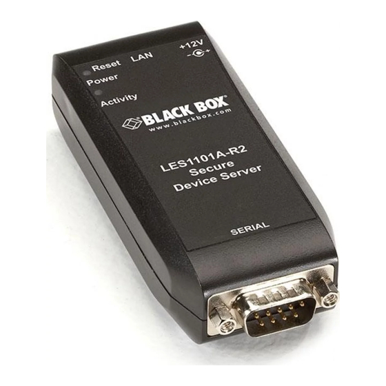
1101 and 1102 Secure Device Servers
Securely monitor, access, and control the computers,
networking devices, telecommunications equipment,
and power supplies in your data room
or communications centers.
Manage your servers:
• Locally across your management LAN
or through the local serial console port.
• Remotely across the Internet or private network.
Customer
Support
Information
Order toll-free in the U.S.: Call 877-877-BBOX (outside U.S. call 724-746-5500) •
FREE technical support 24 hours a day, 7 days a week: Call 724-746-5500 or fax 724-746-0746 •
Mailing address: Black Box Corporation, 1000 Park Drive, Lawrence, PA 15055-1018 •
Web site: www.blackbox.com • E-mail: info@blackbox.com
LES1101A-R2
LES1102A
Advertisement
Table of Contents

Related Manuals for Black Box LES1101A-R2


Summary of Contents for Black Box LES1101A-R2
- Page 1 Order toll-free in the U.S.: Call 877-877-BBOX (outside U.S. call 724-746-5500) • FREE technical support 24 hours a day, 7 days a week: Call 724-746-5500 or fax 724-746-0746 • Support Mailing address: Black Box Corporation, 1000 Park Drive, Lawrence, PA 15055-1018 • Information Web site: www.blackbox.com • E-mail: info@blackbox.com...
- Page 2 1101 and 1102 Secure Device Servers Federal Communications Commission and Industry Canada Radio Frequency Interference Statements This equipment generates, uses, and can radiate radio-frequency energy, and if not installed and used properly, that is, in strict accordance with the manufacturer’s instructions, may cause interference to radio communication. It has been tested and found to comply with the limits for a Class A computing device in accordance with the specifications in Subpart J of Part 15 of FCC rules, which are designed to provide reasonable protection against such interference when the equipment is operated in a commercial environment.
- Page 3 FCC and IC RFI Statements Normas Oficiales Mexicanas (NOM) Electrical Safety Statement INSTRUCCIONES DE SEGURIDAD 1. Todas las instrucciones de seguridad y operación deberán ser leídas antes de que el aparato eléctrico sea operado. 2. Las instrucciones de seguridad y operación deberán ser guardadas para referencia futura. 3.
- Page 4 1101 and 1102 Secure Device Servers Trademarks Used in this Manual Black Box and the Double Diamond logo are registered trademarks of BB Technologies, Inc. Mac is a registered trademark of Apple Computers, Inc. Linux is a registered trademark of Linus Torvalds.
-
Page 5: Table Of Contents
3.1 Power Connection ......................................15 3.2 Network Connection .....................................15 3.3 Serial Port Connection ....................................15 3.3.1 Non RS-232 Serial Port Pinouts—LES1102A..........................16 3.3.2 Non RS-232 Serial Port Pinouts—LES1101A-R2..........................17 4. System Configuration.......................................18 4.1 Management Console Connection ................................18 4.1.1 Connected PC/Workstation Setup ..............................18 4.1.2 Browser Connection ..................................19 4.2 Administrator Password ....................................20... - Page 6 1101 and 1102 Secure Device Servers 6.5 Using SDT Connector for Out-of-Band Connection to the Gateway .....................50 6.6 Importing (and Exporting) Preferences ...............................52 6.7 SDT Connector Public Key Authentication..............................52 6.8 Setting Up SDT for Remote Desktop Access............................. 53 6.8.1 Enable Remote Desktop on the Target Windows Computer to be Accessed ................. 53 6.8.2 Configure the Remote Desktop Connection Client ........................
- Page 7 Table of Contents 10.4.2 Basic Nagios Plug-Ins..................................103 10.4.3 Number of Supported Devices ...............................103 10.4.4 Distributed Monitoring Usage Scenarios............................104 11. System Management......................................106 11.1 System Administration and Reset................................106 11.2 Upgrade Firmware .......................................107 11.3 Configure Date and Time...................................108 11.4 Configuration Backup ....................................108 12. Status Reports ........................................110 12.1 Port Access and Active Users ..................................110 12.2 Statistics ........................................110 12.3 Support Reports ......................................111...
- Page 8 1101 and 1102 Secure Device Servers 15.5 Modifying SNMP Configuration .................................146 15.6 Secure Shell (SSH) Public Key Authentication............................147 15.6.1 SSH Overview ....................................147 15.6.2 Generating Public Keys (Linux) ..............................147 15.6.3 Installing the SSH Public/Private Keys (Clustering) ........................148 15.6.4 Installing SSH Public Keys Authentication (Linux) ........................148 15.6.5 Generating Public/Private Keys for SSH (Windows) ........................150 15.6.6 Fingerprinting....................................151 15.6.7 SSH Tunneled Serial Bridging ................................152...
-
Page 9: Specifications
Humidity Tolerance: 5 to 90% Power: (1) 12-VDC universal input external wallmount power supply,100–240 VAC, 50/60 Hz Size: LES1101A-R2: 4”H x 1.75”W x 1”D (10.2 x 4.5 x 2.5 cm); LES1102A: 3.9”H x 2.8”W x 1”D (10 x 7.2 x 2.5 cm) Weight: LES1101A-R2: 0.25 lb. -
Page 10: Overview
2. Overview 2.1 Introduction This User’s Manual walks you through installing and configuring your Black Box Secure Device Servers (LES1101A-R2 or LES1102A). Each of these products is referred to generically in this manual as a “console server.” Once configured, you will be able to use your console server to securely monitor access and control the computers, networking devices, telecommunications equipment, power supplies, and operating environments in your data room or communications centers. -
Page 11: Management Console
LAN; or connect through an SSH tunneling to the console server. 2.5 Hardware Description 2.5.1 LES1101A-R2 Back Panel Figure 2-2 shows the back panel of the LES1101A-R2. Table 2-1 describes its components. Figure 2-2. LES1101A-R2 back panel. 724-746-5500 | blackbox.com... -
Page 12: Les1101A-R2 Front Panel
Resets the unit back to factory default (RS-232 mode). RJ-45 LED Ethernet Connectivity LED RJ-45 LED Ethernet Activity LED 2.5.2 LES1101A-R2 Front Panel Figure 2-3 shows the LES1101A-R2 front panel. Table 2-2 describes its components. Figure 2-3. LES1101A-R2 front panel. Table 2-2. LES1101A-R2 front-panel components. Number Component Description... -
Page 13: Les1102A Front Panel
Chapter 2: Overview 2.5.3 LES1102A Back Panel Figure 2-4 shows the back panel of the LES1102A. Table 2-3 describes its components. Figure 2-4. LES1102A back panel. Table 2-3. LES1102A back-panel components. Number Component Description Barrel connector Power 8-position Phoenix connector Port 2 (RS-422/485) RJ-45 connector Links to 10/100 Mbps Ethernet... -
Page 14: What's Included
1101 and 1102 Secure Device Servers 2.6 What’s Included Your package should include the following items. If anything is missing or damaged, contact Black Box Technical Support at 724-746-5500 or info@blackbox.com. 2.6.1 LES1101A-R2 • 1101 Secure Device Server • Universal input 12-VDC wallmount power supply •... -
Page 15: Installation
3.3 Serial Port Connection The LES1102A has two DB9 serial ports (Ports 1–2). By default, Port 1 is configured in Local Console (modem) mode. The LES1101A-R2 also has one DB9 serial port that‘s configured by default in Local Console (modem) mode. -
Page 16: Non Rs-232 Serial Port Pinouts-Les1102A
1101 and 1102 Secure Device Servers Table 3-1. RS-232 DB9 connector pinouts. Signal Definition Received Line Signal Detector Received Data Transmitted Data Data Terminal Ready Signal Ground Data Set Ready Request To Send Clear To Send Ring Indicator 3.3.1 Non RS-232 Serial Port Pinouts— LES1102A Port 2 on the LES1102A can also be software selected to be an RS-485 or RS-422 port connected through the screw terminal block (pinout shown in Table 3-2. -
Page 17: Non Rs-232 Serial Port Pinouts-Les1101A-R2
3.3.2 Non RS-232 Serial Port Pinouts— LES1101A-R2 The one DB9 serial port on the LES1101A-R2 can be used as an RS-232, RS-485 or RS-422 port. By default, the LES1101A-R2 is configured in RS-232 mode. RS-422/485 can be set entirely with the user interface (UI)—no jumpers are necessary. To return the unit to factory default (RS-232 mode), press the Reset button. -
Page 18: System Configuration
1101 and 1102 Secure Device Servers 4. System Configuration This chapter provides step-by-step instructions for the console server’s initial configuration, and for connecting it to the Management or Operational LAN. The Administrator must: • Activate the Management Console. • Change the Administrator password. •... -
Page 19: Browser Connection
Chapter 4: System Configuration Figure 4-1. Run screen. Now add a static entry to the ARP table and ping the console server to assign the IP address to the console server. In the example below, a console server has a MAC Address 00:13:C6:00:02:0F (designated on the label on the bottom of the unit) and we are setting its IP address to 192.168.100.23. -
Page 20: Administrator Password
Configure users with access to serial ports on the Serial & Network/Users page (Chapter After completing each of the above steps, you can return to the configuration list by clicking in the top left corner of the screen on the Black Box logo. -
Page 21: Network Ip Address
Chapter 4: System Configuration Figure 4-4. System: Administration screen. 1. Select System: Administration. 2. Enter a new System Password then re-enter it in Confirm System Password. This is the new password for root, the main administrative user account, so choose a complex password, and keep it safe. 3. -
Page 22: System Services
1101 and 1102 Secure Device Servers Figure 4-5. IP Settings screen. If you selected DHCP, the console server will look for configuration details from a DHCP server on your management LAN. This selection automatically disables any static address. The console server MAC address is printed on a label on the base plate. NOTE: In its factory default state (with no Configuration Method selected) the console server has its DHCP client enabled, so it automatically accepts any network IP address assigned by a DHCP server on your network. - Page 23 Chapter 4: System Configuration Figure 4-6. System: Services screen. Select the System: Services option, then select/deselect for the service to be enabled/disabled. The following access protocol options are available: • HTTPS: This ensures secure browser access to all the Management Console menus. It also allows appropriately configured Users secure browser access to selected Management Console Manage menus.
-
Page 24: Communications Software
Administrator (and User) PC/workstation. Black Box provides the SDT Connector Java applet as the recommended client software tool. You can use other generic tools such as PuTTY and SSHTerm. These tools are all described below as well. -
Page 25: Putty
Chapter 4: System Configuration 4.5.2 PuTTY You can also use communications packages like PuTTY to connect to the console server command line (and to connect serially attached devices as covered in Chapter 5). PuTTY is a freeware implementation of Telnet and SSH for Windows and UNIX platforms. It runs as an executable application without needing to be installed onto your system. -
Page 26: Serial Port, Host, Device, And User Configuration
5. Serial Port, Host, Device, and User Configuration The Black Box LES1101A-R2 and LES1102A console server enables access and control of serially attached devices and network attached devices (hosts). The Administrator must configure access privileges for each of these devices, and specify the services that can be used to control the devices. -
Page 27: Common Settings
Chapter 5: Serial Port, Host, Device, and User Configuration Figure 5-2. Serial port screen. Select Serial & Network: Serial Port and you will see the current labels, modes, logging levels, and RS-232 protocol options that are currently set up for each serial port. By default, each serial port is set in Console Server mode. -
Page 28: Console Server Mode
1101 and 1102 Secure Device Servers Before proceeding with further serial port configuration, connect the ports to the serial devices they will be controlling, and make sure they have matching settings. NOTE: The serial ports are all set at the factory to RS-232: 9600 baud, no parity, 8 data bits, 1 stop bit, and Console server Mode. You can change the baud rate to 2400–230400 baud using the management console. - Page 29 Chapter 5: Serial Port, Host, Device, and User Configuration Figure 5-5. Windows features screen. If the remote communications are tunneled with SDT Connector, then you can use Telnet to securely access these attached devices (refer to the Note below). NOTE: In Console Server mode, Users and Administrators can use SDT Connector to set up secure Telnet connections that are SSH tunneled from their client PC/workstations to the serial port on the console server.
- Page 30 1101 and 1102 Secure Device Servers Figure 5-6. PuTTY Configuration screen. PuTTY can be downloaded at http://www.tucows.com/preview/195286.html SSH: We recommend that you use SSH as the protocol where the User or Administrator connects to the console server (or connects through the console server to the attached serial consoles) over the Internet or any other public network.
-
Page 31: Sdt Mode
Chapter 5: Serial Port, Host, Device, and User Configuration This syntax enables Users to set up SSH tunnels to all serial ports with only opening a single IP port 22 in their firewall/gateway. TCP: RAW TCP allows connections directly to a TCP socket. Communications programs like PuTTY also support RAW TCP. You would usually access this protocol via a custom application. -
Page 32: Device (Rpc, Ups, Emd) Mode
1101 and 1102 Secure Device Servers Figure 5-9. SDT settings. For configuration details, refer to Chapter 6.4—Using SDT Connector to Telnet or SSH connect to devices that are serially attached to the console server. 5.1.4 Device (RPC, UPS, EMD) Mode This mode configures the selected serial port to communicate with a serial controlled Uninterruptable Power Supply (UPS), Remote Power Controller/Power Distribution Unit (RPC) or Environmental Monitoring Device (EMD). -
Page 33: Syslog
Chapter 5: Serial Port, Host, Device, and User Configuration Figure 5-12. Serial bridge settings. Select Serial Bridging Mode and specify the IP address of the Server console server and the TCP port address of the remote serial port (for RFC2217 bridging this will be 5001–5002). By default, the bridging client will use RAW TCP. -
Page 34: Add/Edit Users
1101 and 1102 Secure Device Servers 5.2 Add/ Edit Users The Administrator uses this menu selection to set up, edit, and delete users, and to define the access permissions for each of these users. Figure 5-15. Users and Groups screen. Users can be authorized to access specified console server serial ports and specified network-attached hosts. - Page 35 Chapter 5: Serial Port, Host, Device, and User Configuration Figure 5-16. Add a new user screen. Click Add User to add a new user. Add a Username and a confirmed Password for each new user. You may also include information related to the user (for example, contact details) in the Description field.
-
Page 36: Authentication
1101 and 1102 Secure Device Servers 5.3 Authentication Refer to Chapter 9.1—Authentication Configuration for authentication configuration details. 5.4 Network Hosts To access a locally networked computer or device (referred to as a Host), you must identify the Host and specify the TCP or UDP ports/services that will be used to control that Host. -
Page 37: Trusted Networks
Chapter 5: Serial Port, Host, Device, and User Configuration If the console server has been configured with distributed Nagios monitoring enabled, then you will also be presented with Nagios Settings options to enable nominated services on the Host to be monitored (refer to Chapter 10—Nagios Integration). Click Apply. -
Page 38: Managed Devices
Serial device applications Remote Serial Device servers Building automation systems LES1101A-R2 LES1102A Serial/IP redirector virtual Controllers COM ports Sensors Figure 5-19. Serial Port redirection. This serial port redirector software is loaded in your desktop PC, and it allows you to use a serial device that’s connected to the remote console server as if it were connected to your local serial port. - Page 39 Chapter 5: Serial Port, Host, Device, and User Configuration All Users can view (but not edit) these Managed Device connections by selecting Manage: Devices. The Administrator user can edit and add/delete these Managed Devices and their connections. To edit an existing device and add a new connection: •...
-
Page 40: Secure Ssh Tunneling And Sdt Connector
6. Secure SSH Tunneling and SDT Connector Each Black Box console server has an embedded SSH server and uses SSH tunneling so remote users can securely connect through the console server to Managed Devices—using text-based console tools (such as SSH, telnet, SoL) or graphical tools (such VNC, RDP, HTTPS, HTTP, X11, VMware, DRAC, iLO). -
Page 41: Configuring For Ssh Tunneling To Hosts
6.2 SDT Connector Client Configuration The SDT Connector client works with all Black Box console servers. Each of these remote console servers has an embedded OpenSSH based server that you can configure to port forward connections from the SDT Connector client to hosts on their local network (as detailed in the previous chapter). -
Page 42: Configuring A New Console Server Gateway In The Sdt Connector Client
1101 and 1102 Secure Device Servers Once the installer completes you will have a working SDT Connector client installed on your machine and an icon on your desktop: Figure 6-3. SDT connector icon. Click the SDT Connector icon on your desktop to start the client. NOTE: SDT Connector is a Java application, so it must have a Java Runtime Environment (JRE) installed. -
Page 43: Auto-Configure Sdt Connector Client With The User's Access Privileges
Chapter 6: Secure SSH Tunneling and SDT Connector Figure 6-5. New SDT Gateway screen. Or, enter a Descriptive Name to display instead of the IP or DNS address, and any Notes or a Description of this gateway (such as its firmware version, site location, or anything special about its network configuration). -
Page 44: Make An Sdt Connection Through The Gateway To The Host
1101 and 1102 Secure Device Servers Figure 6-7. Hosts. NOTE: The Retrieve Hosts function will auto-configure all user classes (that is, they can be members of user or admin or some other group or no group. SDT Connector will not auto-configure the root (and we recommend that you only use this account for initial config and to add an initial admin account to the console server). -
Page 45: Manually Adding New Services To The New Hosts
Chapter 6: Secure SSH Tunneling and SDT Connector Figure 6-9. New SDT Host screen. Enter the IP or DNS Host Address of the host (if this is a DNS address, it must be able to be resolved by the gateway). Select which Services to use to access the new host. - Page 46 1101 and 1102 Secure Device Servers Select which Client application is associated with the new service. A range of client application options are pre-configured in the default SDT Connector (RDP client, VNC client, HTTP browser, HTTPS browser, Telnet client, etc.). If you want to add new client applications to this range, proceed to the next section (Adding a new client), then return here.
-
Page 47: Adding A Client Program To Be Started For The New Service
Chapter 6: Secure SSH Tunneling and SDT Connector Enter a local TCP port to bind to when creating the local endpoint of the redirection. If you leave this blank, a random port is selected. Figure 6-13. Edit port redirection. NOTES: SDT Connector can also tunnel UDP services. SDT Connector tunnels the UDP traffic through the TCP SSH redirection, so it is a “tunnel within a tunnel.”... - Page 48 1101 and 1102 Secure Device Servers Enter a Name for the client. Enter the Path to the executable file for the client (or click Browse to locate the executable). Enter a Command Line associated with launching the client application. SDT Connector typically launches a client using command line arguments to point it at the local endpoint of the redirection.
-
Page 49: Sdt Connector To Management Console
Browse to the console server and select Network Hosts from Serial & Network, click Add Host, and in the IP Address/DNS Name field enter 127.0.0.1 (this is the Black Box network loopback address). Then, enter Loopback in Description. Remove all entries under Permitted Services except for those that you will use to access the Management Console (80/http or 443/https) or the command line (22/ssh or 23/telnet). -
Page 50: 1101 And 1102 Secure Device Servers
Select Network Hosts from Serial & Network and click Add Host. In the IP Address/DNS Name field enter 127.0.0.1 (this is the Black Box network loopback address) and enter Loopback in Description. Remove all entries under Permitted Services, select TCP, and enter 200n in Port. (This configures the Telnet port enabled in the previous step, so for Port 2 you would enter 2002.) - Page 51 Chapter 6: Secure SSH Tunneling and SDT Connector SDT Connector allows for maximum flexibility. It allows you to provide your own scripts or commands for starting and stopping the OoB connection. Figure 6-19. Out-of-band access. To configure SDT Connector for OoB access: When adding a new Gateway or editing an existing Gateway select the Out Of Band tab.
-
Page 52: Importing (And Exporting) Preferences
1101 and 1102 Secure Device Servers Figure 6-20. OoB connection using SDT connector. When you connect to a service on a host behind the console server, or to the console server itself, SDT Connector will initiate the OoB connection using the provided Start Command. The OoB connection does not stop (using the provided Stop Command) until you click off Out Of Band under Gateway Actions;... -
Page 53: Setting Up Sdt For Remote Desktop Access
The Microsoft Remote Desktop Protocol (RDP) enables the system manager to securely access and manage remote Windows computers—to reconfigure applications and user profiles, upgrade the server’s operating system, reboot the machine, etc. Black Box’s Secure Tunneling uses SSH tunneling, so this RDP traffic is securely transferred through an authenticated and encrypted tunnel. -
Page 54: Configure The Remote Desktop Connection Client
1101 and 1102 Secure Device Servers Figure 6-23. Remote Desktop Users dialog box. To set the user(s) who can remotely access the system with RDP, click Add on the Remote Desktop Users dialog box. NOTE: If you need to set up new users for Remote Desktop access, open User Accounts in the Control Panel and follow the steps to nominate the new user’s name, password, and account type (Administrator or Limited). - Page 55 Chapter 6: Secure SSH Tunneling and SDT Connector In Computer, enter the appropriate IP Address and Port Number: Where there is a direct local or enterprise VPN connection, enter the IP Address of the console server, and the Port Number of the SDT Secure Tunnel for the console server serial port that you attach to the Windows computer you want to control.
-
Page 56: Sdt Ssh Tunnel For Vnc
1101 and 1102 Secure Device Servers Geometry: width x height or 70% screen percentage Use –p to receive password prompt You can use GUI front end tools like the GNOME Terminal Services Client tsclient to configure and launch the rdesktop client. (Using tsclient also enables you to store multiple configurations of rdesktop for connection to many servers.) Figure 6-26. - Page 57 Chapter 6: Secure SSH Tunneling and SDT Connector Windows does not include VNC software, so you will need to download, install, and activate a third party VNC Server software package: RealVNC http://www.realvnc.com is fully cross-platform, so a desktop running on a Linux machine may be displayed on a Windows PC, on a Solaris machine, or on any number of other architectures.
-
Page 58: Install, Configure, And Connect The Vnc Viewer
1101 and 1102 Secure Device Servers • Start the service with service vncserver start • Edit /home/username/.vnc/xstartup if you want a more advanced session than just twm and an xterm. For Macintosh servers (and clients): OSXvnc http://www.redstonesoftware.com/vnc.html is a robust, full-featured VNC server for Mac OS X that allows any VNC client to remotely view and/or control the Mac OS X machine. -
Page 59: Using Sdt To Connect To Hosts That Are Serially Attached To The Gateway
Chapter 6: Secure SSH Tunneling and SDT Connector Figure 6-29. IP address of console server unit. To establish the VNC connection, simply activate the VNC Viewer software on the Viewer PC and enter the password. Figure 6-30. VNC authentication. NOTE: For general background reading on Remote Desktop and VNC access we recommend the following: The Microsoft Remote Desktop How-To. -
Page 60: Establish A Ppp Connection Between The Host Com Port And The Console Server
1101 and 1102 Secure Device Servers 6.10.1 Establish a PPP Connection between the Host COM Port and Console Server (This step is only necessary for serially connected computers.) First, physically connect the COM port on the host computer you want to access to the serial port on the console server, then: For non Windows (Linux, UNIX, Solaris, etc.) computers, establish a PPP connection over the serial port. - Page 61 Chapter 6: Secure SSH Tunneling and SDT Connector Figure 6-32. User permissions. Specify which Users will be allowed to use this connection. This should be the same Users who were given Remote Desktop access privileges in the earlier step. Click Next. On the Network Connection screen, select TCP/IP and click Properties.
-
Page 62: Setup Sdt Serial Ports On The Console Server
1101 and 1102 Secure Device Servers Also, you could use the console server default username and password when you set up the new Remote Desktop User and gave this User permission to use the advance connection to access the Windows computer: NOTES (continued): The console server default Username is portXX where XX is the serial port number on the console server. -
Page 63: Setup Sdt Connector To Ssh Port Forward Over The Console Server Serial Port
Chapter 6: Secure SSH Tunneling and SDT Connector Figure 6-35. SDT settings screen. NOTE: When you enable SDT, it will override all other Configuration protocols on that port. NOTE: If you leave the Username and User Password fields blank, they default to portXX and portXX where XX is the serial port number. The default username and password for Secure RDP over Port 2 is port02. - Page 64 1101 and 1102 Secure Device Servers Figure 6-36. PuTTY Configuration screen. In the Session menu, enter the IP address of the console server in the Host Name or IP address field. For dial-in connections, this IP address will be the Local Address that you assigned to the console server when you set it up as the Dial-In PPP Server.
- Page 65 Chapter 6: Secure SSH Tunneling and SDT Connector Figure 6-37. Set destination. If your destination computer is serially connected to the console server, set the Destination as <port label>:3389. For example, if the Label you specified on the serial port on the console server is win2k3, then specify the remote host as win2k3:3389. Or, you can set the Destination as portXX:3389 (where XX is the SDT enabled serial port number).
- Page 66 1101 and 1102 Secure Device Servers NOTE: How secure is VNC? VNC access generally allows access to your whole computer, so security is very important. VNC uses a random challenge-response system to provide the basic authentication that allows you to connect to a VNC server. This is reasonably secure and the password is not sent over the network.
-
Page 67: Alerts And Logging
Chapter 7: Alerts and Logging 7. Alerts and Logging This chapter describes the alert generation and logging features of the console server. The Alert facility monitors the serial ports, all logins, and the power status, and sends emails, SMS, Nagios, or SNMP alerts when specified trigger events occur. First, enable and configure the service that will be used to carry the alert (Section 7.1). -
Page 68: Sms Alerts
1101 and 1102 Secure Device Servers You may also enter a Username and Password if the SMTP server requires authentication. You can specify the specific Subject Line that will be sent with the email. Click Apply to activate SMTP. 7.1.2 SMS Alerts The console server uses email-to-SMS services to send SMS alert notifications to mobile devices. -
Page 69: Nagios Alerts
Chapter 7: Alerts and Logging To configure for SNMP v3, you will need to enter an ID and authentication password and contact information for the local Administrator (in the Security Name). Click Apply to activate SNMP. Figure 7-3. SNMP alerts. NOTE: All console servers have the snmptrap daemon to send traps/notifications to remote SNMP servers on defined trigger events as detailed above. -
Page 70: Add A New Alert
1101 and 1102 Secure Device Servers Select Alerts & Logging: Alerts, which will display all the alerts currently configured. Click Add Alert. 7.2.1 Add a New Alert The first step is to specify the alert service that this event will use for sending notification, who to notify there, and what port/host/device is to be monitored: Figure 7-5. - Page 71 Chapter 7: Alerts and Logging Figure 7-6. General alert types. Serial Port Signal Alert—This alert will be triggered when the specified signal changes state and applies to serial ports only. You must specify the particular Signal Type (DSR, DCD or CTS) trigger condition and the Applicable Ports(s). Figure 7-7.
-
Page 72: Configuring Power Alert Type
1101 and 1102 Secure Device Servers Figure 7-8. Serial port pattern match alert. UPS Power Status Alert— This alert will be triggered when the UPS power status changes between on line, on battery, and low battery. This status will only be monitored on the Applicable UPS(es) you select. Power Alert—(next section). -
Page 73: Remote Log Storage
Chapter 7: Alerts and Logging 7.3 Remote Log Storage Before activating Serial or Network Port Logging on any port or UPS logging, you must specify where those logs are to be saved: Select the Alerts & Logging: Port Log menu option and specify the Server Type to use, and the details to enable log server access. Figure 7-11. - Page 74 1101 and 1102 Secure Device Servers Level 2 Logs all data transferred to and from the port. Click Add then click Apply. 724-746-5500 | blackbox.com...
-
Page 75: Power Management
Chapter 8: Power Management 8. Power Management Black Box console servers manage embedded software that you can use to manage connected Power Distribution Systems (PDUs), IPMI devices, and Uninterruptible Power Supplies (UPSs) supplied by a number of vendors. 8.1 Remote Power Control (RPC) The console server Management Console monitors and controls Remote Power Control (RPC) devices using the embedded PowerMan and Network UPS Tools open source management tools and the Black Box power management software. - Page 76 Network UPS Tools. If you are connecting to the RPC by a serial port, you will be presented with all the serial RPC types currently supported by the embedded PowerMan and the Black Box power manager: 724-746-5500 | blackbox.com...
-
Page 77: Rpc Access Privileges And Alerts
NOTE: The Black Box console servers support most popular network and serial PDUs. If your PDU is not on the default list, then you can add support directly (as covered in Chapter 15—Advanced Configurations) or add the PDU support to either the Network UPS Tools or PowerMan open source projects. -
Page 78: Rpc Status
8.2 Uninterruptible Power Supply Control (UPS) You can configure all Black Box console servers to manage locally and remotely connected UPS hardware using Network UPS Tools. Network UPS Tools (NUT) is a group of open source programs that provide a common interface for monitoring and administering UPS hardware. -
Page 79: Managed Ups Connections
Chapter 8: Power Management LES1102A Multiple local (serial USB networked) UPSes Managed UPS LES1102A Remote UPS Multiple remote UPSes Figure 8-5. Connecting to remote UPS. 8.2.1 Managed UPS Connections A Managed UPS is a UPS that is directly connected as a Managed Device to the console server. You can connect it via serial or USB cable or by the network. - Page 80 1101 and 1102 Secure Device Servers Serial and network connected UPSes must first be connected to, and configured to communicate with the console server: For serial UPSes attach the UPS to the selected serial port on the console server. From the Serial and Network: Serial Port menu, configure the Common Settings of that port with the RS-232 properties, etc.
- Page 81 Chapter 8: Power Management Figure 8-8. Add managed UPS screen. Select if the UPS will be Connected Via USB, over a pre-configured serial port, or via SNMP/HTTP/HTTPS over the preconfigured network Host connection. When you select a network UPS connection, then the corresponding Host Name/Description that you set up for that connection will be entered as the Name and Description for the power device.
-
Page 82: Remote Ups Management
You can configure the upsc and upslog clients in the Black Box console server to monitor remote servers that are running Network UPS Tools managing their locally connected UPSes. These remote servers might be other Black Box console servers or generic Linux servers running NUT. You can centrally monitor all these distributed UPSes (which may be spread in a row in a data center, around a campus property, or across the country) through the one central console server window. -
Page 83: Controlling Ups Powered Computers
Chapter 8: Power Management Enter the IP Address or DNS name of the remote console server* that is managing the remote UPS. (*This may be another Black Box console server or it may be a generic Linux server running Network UPS Tools.) NOTE: An example where centrally monitor remotely distributed UPSes is useful is a campus or large business site where there’s a multitude of... -
Page 84: Overview Of Network Ups Tools (Nut)
1101 and 1102 Secure Device Servers Figure 8-11. UPS graph. Click on any particular All Data for any UPS System in the table for more status and configuration information about the selected UPS System. Select UPS Logs and you will be presented with the log table of the load, battery charge level, temperature, and other status information from all the Managed and Monitored UPS systems. - Page 85 Livermore Labs that also is embedded in Black Box console servers). These NUT clients and servers all are embedded in each Black Box console server (with a Management Console presentation layer added) —and they also are run remotely on distributed console servers and other remote NUT monitoring systems. This layered distributed NUT architecture enables: Multiple manufacturer support: NUT can monitor UPS models from 79 different manufacturers—and PDUs from a growing number of vendors—...
- Page 86 1101 and 1102 Secure Device Servers Central management of multiple NUT servers: A central NUT client can monitor multiple NUT servers that may be distributed throughout the data center, across a campus, or around the world. NUT supports the more complex power architectures found in data centers, communications centers, and distributed office environments where many UPSes from many vendors power many systems with many clients.
-
Page 87: Authentication
Chapter 9: Authentication 9. Authentication The console server is a dedicated Linux computer with a myriad of popular and proven Linux software modules for networking, secure access (OpenSSH), and communications (OpenSSL), and sophisticated user authentication (PAM, RADIUS, TACACS+, and LDAP). This chapter details how the Administrator can use the Management Console to establish remote AAA authentication for all connections to the console server and attached serial and network host devices. -
Page 88: Radius Authentication
1101 and 1102 Secure Device Servers Figure 9-2. TACACS screen. Enter the Server Address (IP or host name) of the remote Authentication/Authorization server. Multiple remote servers may be specified in a comma-separated list. Each server is tried in succession. In addition to multiple remote servers, you can also enter separate lists of Authentication/Authorization servers and Accounting servers. If no Accounting servers are specified, the Authentication/Authorization servers are used instead. -
Page 89: Ldap Authentication
Users may be added to the local console server appliance. If they are not added and they log in via remote AAA, a user will be added for them. This user will not show up in the Black Box configurators unless they are specifically added, at which point they are transformed into a completely local user. -
Page 90: Pluggable Authentication Modules (Pam)
Users added on demand: When a user attempts to log in, but does not already have an account on the console server, a new user account will be created. This account will have no rights, and no password set. It will not appear in the Black Box configuration tools. Automatically added accounts will not be able to log in if the remote servers are unavailable. -
Page 91: Ssl Certificate
Chapter 9: Authentication 9.3 SSL Certificate The console server uses the Secure Socket Layer (SSL) protocol for encrypted network traffic between itself and a connected user. When establishing the connection, the console server has to expose its identity to the user’s browser using a cryptographic certificate. The default certificate that comes with the console server device upon delivery is for testing purposes only. - Page 92 1101 and 1102 Secure Device Servers Select System: SSL Certificate and fill out the fields as explained below: Common name This is the network name of the console server once it is installed in the network (usually the fully qualified domain name). It is identical to the name that is used to access the console server with a web browser (without the “http://”...
- Page 93 Chapter 9: Authentication Figure 9-6. Upload button. After completing these steps, the console server has its own certificate that is used for identifying the console server to its users. NOTE: You can find information on issuing certificates and configuring HTTPS from the command line in Chapter 14. 724-746-5500 | blackbox.com...
-
Page 94: Nagios Integration
1101 and 1102 Secure Device Servers 10. Nagios Integration Nagios is a powerful, highly extensible open source tool for monitoring network hosts and services. The core Nagios software package will typically be installed on a server or virtual server, the central Nagios server. Console servers operate in conjunction with a central/upstream Nagios server to distribute and monitor attached network hosts and serial devices. -
Page 95: Central Management And Setting Up Sdt For Nagios
Chapter 10: Nagios Integration 10.2 Central Management and Setting Up SDT for Nagios The Black Box Nagios solution has three parts: the Central Nagios server, Distributed Black Box console servers, and the SDT for Nagios software. Central Nagios server LES1102A... -
Page 96: Setup Central Nagios Server
Enter the IP address that the distributed Black Box console server will use to contact the central Nagios server in Nagios Server Address. Enter the IP address that the clients running SDT Connector will use to connect through the distributed Black Box servers in SDT Gateway address. - Page 97 Chapter 10: Nagios Integration Click Apply. Next, you must configure the attached Window network host and specify the services you will be checking with Nagios (HTTP and HTTPS): Select Network Hosts from the Serial & Network menu and click Add Host. Enter the IP Address/DNS Name of the network server, for example: 192.168.1.10 and enter a Description, for example: Windows 2003 IIS Server.
-
Page 98: Configuring Nagios Distributed Monitoring
1101 and 1102 Secure Device Servers Finally, you need to add a User for the client running SDT Connector: Select Users & Groups from the Serial & Network menu. Click Add User. In Username, enter: sdtnagiosuser, then enter and confirm a Password. In Accessible Hosts click the IP address/DNS name of the IIS server, and in Accessible Ports click the serial port that has the router console port attached. -
Page 99: Enable Nrpe Monitoring
Chapter 10: Nagios Integration 10.3.2 Enable NRPE Monitoring LES1102A Serial check_ Nagios NRPE nrpe Network Nagios monitoring host Remote Console server Remote managed devices Figure 10-5. NRPE monitoring structure. Enabling NRPE allows you to execute plug-ins (such as check_tcp and check_ping) on the remote Console server to monitor serial or network attached remote servers. -
Page 100: Configure Selected Serial Ports For Nagios Monitoring
NSCA as a primary method, falling back to NRPE if a check was late— for details, see the Nagios documentation (http://www.nagios.org/docs/) on Service and Host Freshness Checks ; Host definitions ; Black Box console server define host{ generic-host... - Page 101 Chapter 10: Nagios Integration host_name Black Box alias Console server address 192.168.254.147 ; Managed Host define host{ generic-host host_name server alias server address 192.168.254.227 ; NRPE daemon on gateway define command { command_name check_nrpe_daemon command_line $USER1$/check_nrpe -H 192.168.254.147 -p 5666...
- Page 102 Black Box_nrpe_daemon_dep host_name Black Box dependent_host_name server dependent_service_description Port Log service_description NRPE Daemon execution_failure_criteria w,u,c ; Ping define command{ command_name check_ping_via_Black Box command_line $USER1$/check_nrpe -H 192.168.254.147 -p 5666 -c host_ping_$HOSTNAME$...
-
Page 103: Basic Nagios Plug-Ins
Each console server is preconfigured with two checks that are specific to Black Box: check_serial_signals is used to monitor the handshaking lines on the serial ports check_port_log is used to monitor the data logged for a serial port. -
Page 104: Distributed Monitoring Usage Scenarios
1101 and 1102 Secure Device Servers 10.4.4 Distributed Monitoring Usage Scenarios Below are a number of distributed monitoring Nagios scenarios: Local office In this scenario, the console server is set up to monitor each managed device’s console. Configure it to make a number of checks, either actively at the Nagios server's request, or passively at preset intervals, and submit the results to the Nagios server in a batch. - Page 105 Chapter 10: Nagios Integration Remote site with restrictive firewall In this scenario, the role of the console server will vary. One aspect may be to upload check results through NSCA. Another may be to provide an SSH tunnel to allow the Nagios server to run NRPE commands. Nagios SSH travel initiated for remote site NRPE server at branch server‘s request...
-
Page 106: System Management
1101 and 1102 Secure Device Servers 11. System Management This chapter describes how the Administrator can perform a range of general console server system administration and configuration tasks such as: • Applying Soft and Hard Resets to the gateway. • Re-flashing the Firmware. •... -
Page 107: Upgrade Firmware
Or select Status: Support Report and note the Firmware Version. Figure 11-3. Firmware version. To upgrade, you first must download the latest firmware image from the Black Box.web site. Save this downloaded firmware image file to a system on the same subnet as the console server. -
Page 108: Configure Date And Time
1101 and 1102 Secure Device Servers Click Apply and the console server appliance will perform a soft reboot and start upgrading the firmware. This process will take several minutes. After the firmware upgrade completes, click here to return to the Management Console. Your console server will have retained all its pre-upgrade configuration information. - Page 109 Chapter 11: System Management Figure 11-6. Configuration backup screen. With all console servers, you can save the backup file remotely on your PC and you can restore configurations from remote locations: Click Save Backup in the Remote Configuration Backup menu. The config backup file (System Name_date_config.opg) will be downloaded to your PC and saved in the location you nominate.
-
Page 110: Status Reports
1101 and 1102 Secure Device Servers 12. Status Reports This chapter describes the dashboard feature and the status reports that are available: • Port Access and Active Users • Statistics • Support Reports • Syslog • Dashboard Other status reports that are covered elsewhere include: •... -
Page 111: Support Reports
You can find detailed statistics reports by selecting the various submenus. 12.3 Support Reports The Support Report provides useful status information that will assist the Black Box Technical Support team to solve any problems you may experience with your console server. -
Page 112: Syslog
1101 and 1102 Secure Device Servers 12.4 Syslog The Linux System Logger in the console server maintains a record of all system messages and errors: Select Status: Syslog You can redirect the syslog record to a remote Syslog Server: Enter the remote Syslog Server Address and Syslog Server Port details and click Apply. The console maintains a local Syslog. -
Page 113: Configuring The Dashboard
Chapter 12: Status Reports 12.5.1 Configuring the Dashboard Only users who are members of the admin group (and the root user) can configure and access the dashboard. To configure a custom dashboard: Select System: Configure Dashboard and select the user (or group) you are configuring this custom dashboard layout for. Click Next. -
Page 114: Creating Custom Widgets For The Dashboard
1101 and 1102 Secure Device Servers To configure what is to be displayed by each widget: Go to the Configure widgets panel and configure each selected widget (for example, specify which UPS status is to be displayed on the ups widget or the maximum number of Managed Devices to be displayed in the devices widget). -
Page 115: Management
Chapter 13: Management 13. Management The console server has a small number of Manage reports and tools that are available to both Administrators and Users: • Access and control authorized devices. • View serial port logs and host logs for those devices. •... -
Page 116: Serial Port Terminal Connection
1101 and 1102 Secure Device Servers Figure 13-3. Port logs. To display Host logs, select Manage: Host Logs and the Host to be displayed. 13.3 Serial Port Terminal Connection Administrator and Users can communicate directly with the console server command line and with devices attached to the console server serial ports using SDT Connector and their local tenet client, or use a java terminal in their browser. -
Page 117: Power Management
Chapter 13: Management NOTE: You must install SDT Connector on the computer you are browsing from and add and the console server as a gateway as detailed in Chapter 6. The alternate to using SDT Connector and your local telnet client is to run the open source jcterm java terminal applet into your browser to connect to the console server and attached serial port devices. -
Page 118: Configuration From The Command Line
Without care, these configurations may not withstand a power-cycle- reset or reconfigure. Black Box provides a number of custom command line utilities and scripts to make it simple to configure the console server and make sure the changes are stored in the console server's flash memory, etc. - Page 119 Chapter 14: Configuration from the Command Line The config tool Syntax config [ -ahv ] [ -d id ] [ -g id ] [ -p path ] [ -r configurator ] [ -s id=value ] [ -P id ] Description The config tool is designed to perform multiple actions from one command if needed, so options can be chained together.
-
Page 120: Serial Port Configuration
1101 and 1102 Secure Device Servers The registered configurators are: alerts ipconfig auth nagios cascade power console serialconfig dhcp services dialin slave eventlog systemsettings hosts time ipaccess users There are three ways to delete a config element value. The simplest way is use the delete-node script detailed later in this chapter. You can also assign the config element to "", or delete the entire config node using -d: # /bin/config -d 'element name' All passwords are saved in plaintext except the user passwords and the system passwords, which are encrypted. - Page 121 Chapter 14: Configuration from the Command Line NOTE: Supported serial port baud-rates are ‘50’, ‘75’, ‘110’, ‘134’, ‘150’, ‘200’, ‘300’, ‘600’, ‘1200’, ‘1800’, ‘2400’, ‘4800’, ‘9600’, '19200', '38400', '57600', '115200', and '230400'. Supported parity values are 'None', 'Odd', 'Even', 'Mark' and 'Space'. Supported data-bits values are '8', '7', '6', and '5'.
-
Page 122: Adding And Removing Users
1101 and 1102 Secure Device Servers # config -s config.ports.port5.sdt.ssh=on To configure a username and password when accessing this port with Username = user1 and Password = secret: # config -s config.ports.port#.sdt.username=user1 # config -s config.ports.port#.sdt.password=secret Terminal server mode Enable a TTY login for a local terminal attached to serial port 5: # config -s config.ports.port5.mode=terminal # config -s config.ports.port5.terminal=[vt220 | vt102 | vt100 | linux | ansi] The default terminal is vt220. - Page 123 Chapter 14: Configuration from the Command Line Your new User will be the existing total plus 1. If the previous command gave you 0, then you start with user number 1. If you already have 1 user your new user will be number 2, etc. To add a user (with Username=John, Password=secret and Description=mySecondUser) issue the commands: # config -s config.users.total=2 (assuming we already have 1 user configured) # config -s config.users.user2.username=John...
-
Page 124: Adding And Removing User Groups
1101 and 1102 Secure Device Servers 14.4 Adding and Removing User Groups The console server is configured with a few default user groups (even though only two of these groups are visible in the Management Console GUI). To find out how many groups are already present: # config -g config.groups.total Assume this value is six. -
Page 125: Network Hosts
Chapter 14: Configuration from the Command Line To configure TACACS authentication: # config -s config.auth.tacacs.auth_server='comma separated list' (list of remote authentiction and authorization servers.) # config -s config.auth.tacacs.acct_server='comma separated list' (list of remote accounting servers. If unset, Authentication and Authorization Server Address will be used.) # config -s config.auth.tacacs.password='password' To configure RADIUS authentication: # config -s config.auth.radius.auth_server='comma separated list' (list of remote authentiction and authorization servers.) -
Page 126: Trusted Networks
1101 and 1102 Secure Device Servers Add other network host To add any other type of network host with the following details: IP address/ DNS name 192.168.3.10 Host name OfficePC Description MyPC Allowed sevices ssh port 22,https port 443 log level for services Issue the commands below. -
Page 127: Cascaded Ports
Chapter 14: Configuration from the Command Line The following command will synchronize the live system with the new configuration: # config -r serialconfig 14.8 Cascaded Ports To add a new slave device with the following settings: IP address/DNS name 192.168.0.153 Description Console in office 42 Label... -
Page 128: Rpc Connections
1101 and 1102 Secure Device Servers # config -s config.ups.monitors.monitor1.options.option1.opt=option # config -s config.ups.monitors.monitor1.options.option1.arg=argument # config -s config.ups.monitors.monitor1.options.total=1 # config -s config.ups.monitors.monitor1.log.enabled=on # config -s config.ups.monitors.monitor1.log.interval=2 # config -s config.ups.monitors.monitor1.script.enabled=on Make sure to increment the total monitors: # config -s config.ups.monitors.total=1 The five commands below will add the UPS to Managed devices. -
Page 129: Managed Devices
Chapter 14: Configuration from the Command Line # config -s config.ports.port2.power.type=APC 7900 # config -s config.ports.port2.power.name=MyRPC # config -s "config.ports.port2.power.description=RPC in room 5" # config -s config.ports.port2.power.username=rpclogin # config -s config.ports.port2.power.password=secret # config -s config.ports.port2.power.snmp.community=v1 # config -s config.ports.port2.power.log.enabled=on # config -s config.ports.port2.power.log.interval=600 # config -s config.ports.port2.power.outlets=4 The following five commands are used by the Management Console to add the RPC to “Managed Devices”: # config -s config.devices.device3.connections.connection1.name=myRPC... -
Page 130: Alerts
You can add an email, SNMP, or NAGIOS alert by following the steps below. The general settings for all alerts Assume this is our second alert, and we want to send alert emails to john@Black Box.com and sms's to peter@Black Box.com: # config -s config.alerts.alert2.description=MySecondAlert # config -s config.alerts.alert2.email=john@Black Box.com... -
Page 131: Smtp And Sms
Server password secret Subject line SMTP alerts # config -s config.system.smtp.server=mail.Black Box.com # config -s config.system.smtp.encryption=SSL (can also be TLS or None ) # config -s config.system.smtp.sender=John@Black Box.com # config -s config.system.smtp.username=john # config -s config.system.smtp.password=secret 724-746-5500 | blackbox.com... -
Page 132: Snmp
1101 and 1102 Secure Device Servers # config -s config.system.smtp.subject=SMTP alerts To set-up an SMTP SMS server with the same details as above: # config -s config.system.smtp.server2=mail.Black Box.com # config -s config.system.smtp.encryption2=SSL (can also be TLS or None ) # config -s config.system.smtp.sender2=John@Black Box.com # config -s config.system.smtp.username2=john... -
Page 133: Date And Time Settings
Chapter 14: Configuration from the Command Line # config -s config.interfaces.wan.mode=static # config -s config.interfaces.wan.media=[ Auto | 100baseTx-FD | 100baseTx-HD | 10baseT-HD ] 10baseT-FD To enable bridging between all interfaces: # config -s config.system.bridge.enabled=on To enable IPv6 for all interfaces # config -s config.system.ipv6.enabled=on To configure the management LAN interface, use the same commands as above but replace: config.interfaces.wan, with config.interfaces.lan... -
Page 134: Dhcp Server
1101 and 1102 Secure Device Servers The following command will synchronize the live system with the new configuration: # config -r time 14.19 DHCP Server To enable the DHCP server on the console management LAN, with settings: Default lease time 200000 seconds Maximum lease time 300000 seconds... -
Page 135: Nagios
Chapter 14: Configuration from the Command Line The following command will synchronize the live system with the new configuration: # config –a 14.21 NAGIOS To configure NAGIOS with the following settings: NAGIOS host name console at R3 (Name of this system) NAGIOS host address 192.168.0.1 (IP to find this device at) NAGIOS server address... -
Page 136: Custom Scripting
1101 and 1102 Secure Device Servers Black Box console servers run the embedded Linux operating system. So Administrator class users can configure the console server and monitor and manage attached serial console and host devices from the command line using Linux commands and the config utility as described in Chapter 14. -
Page 137: Advanced Configuration
Chapter 15: Advanced Configuration For power and alarm sensor alerts (power load, and battery charge alerts): /etc/scripts/environmental-alert For an interface failover alert: /etc/scripts/interface-failover-alert All of these scripts do a check to see whether you have created a custom script to run instead. The code that does this check is shown below (an extract from the file /etc/scripts/portmanager-pattern-alert): # If there's a user-configured script, run it instead scripts[0]="/etc/config/scripts/pattern-alert.${ALERT_PORTNAME}"... -
Page 138: Deleting Configuration Values From The Cli
1101 and 1102 Secure Device Servers email to more than one email address, find the lines in the script responsible for invoking the alert-email script, then add the following lines below the existing lines: export TOADDR="emailaddress@domain.com" /bin/sh /etc/scripts/alert-email $suffix & These two lines assign a new email address to TOADDR and invoke the alert-email script in the background. - Page 139 Chapter 15: Advanced Configuration NEWTOTAL=$[ $TOTAL -1 ] # Make backup copy of config file cp /etc/config/config.xml /etc/config/config.bak echo "backup of /etc/config/config.xml saved in /etc/config/config.bak" if [ -z $NUMBER ] # test whether a singular node is being \ #deleted e.g. config.sdt.hosts then echo "deleting $1"...
-
Page 140: Power Cycle Any Device When A Ping Request Fails
1101 and 1102 Secure Device Servers echo Done exit 0 else echo "error: item being deleted has an index greater than total items. Increase the total count variable." exit 0 The ping-detect script is designed to run specified commands when a monitored host stops responding to ping requests. The first parameter taken by the ping-detect script is the hostname/IP address of the device to ping. -
Page 141: Running Custom Scripts When A Configurator Is Invoked
Chapter 15: Advanced Configuration sleep 30s if [ "$COUNTER" -eq 5 ] then COUNTER=0 "$@" sleep 2s done A configurator is responsible for reading the values in /etc/config/config.xml and making the appropriate changes live. Some changes made by the configurators are part of the Linux configuration itself, such as user passwords or ipconfig. Currently there are nineteen configurators. -
Page 142: Backing Up The Configuration Off-Box
1101 and 1102 Secure Device Servers To save the configuration: # /etc/scripts/backup-usb save config-20May To check if the backup was saved correctly: # /etc/scripts/backup-usb list If this command does not display "* config-20May" then there was an error saving the configuration. The set-default command takes an input file as an argument and renames it to "default.opg". -
Page 143: Advanced Portmanager
Chapter 15: Advanced Configuration Black Box’s portmanger program manages the console server serial ports. It routes network connection to serial ports, checks permissions, and monitors and logs all the data flowing to/from the ports. pmshell The pmshell command acts similar to the standard tip or cu commands, but all serial port access is directed via the portmanager. -
Page 144: External Scripts And Alerts
1101 and 1102 Secure Device Servers portmanager daemon There is normally no need to stop and restart the daemon. To restart the daemon normally, just run the command: # portmanager Supported command line options are: Force portmanager to run in the foreground: --nodaemon Set the level of debug logging: --loglevel={debug,info,warn,error,alert}... -
Page 145: Raw Access To Serial Ports
Chapter 15: Advanced Configuration </etc/config/pmshell-start.sh> You can use tip and stty to completely bypass the portmanager and have raw access to the serial ports. When you run tip on a portmanager controlled port, portmanager closes that port, and stops monitoring it until tip releases control of it. With stty, the changes made to the port only “stick”... - Page 146 1101 and 1102 Secure Device Servers If the standard system firewall configuration is not adequate for your needs you can bypass it safely by creating a file at /etc/config/filter-custom containing commands to build a specialized firewall. This firewall script will run whenever the LAN interface is brought up (including initially) and will override any automated system firewall settings.
- Page 147 (to external libraries), all known security bugs fixed, new features reintroduced, and many other clean-ups. The only changes in the Black Box SSH implementation are: PAM support EGD[1]/PRNGD[2] support and replacements for OpenBSD library functions that are absent from other versions of UNIX The config files are now in /etc/config.
-
Page 148: Fingerprinting
The key fingerprint is: 28:aa:29:38:ba:40:f4:11:5e:3f:d4:fa:e5:36:14:d6 user@server Make sure that there is no password associated with the keys. If there is a password, then the Black Box devices will have no way to supply it as runtime. Full documentation for the ssh-keygen command can be found at For Black Box console servers, the keys can be simply uploaded through the web interface, on the System: Administration page. - Page 149 Figure 15-1. If the Black Box device selected to be the server will only have one client device, then the authorized_keys file is simply a copy of the public key for that device. If one or more devices will be clients of the server, then the authorized_keys file will contain a copy of all of the public keys. RSA and DSA keys may be freely mixed in the authorized_keys file.
- Page 150 This section describes how to generate and configure SSH keys using Windows. First create a new user from the Black Box Management (the following example uses a user called "testuser"), making sure it is a member of the "users" group.
- Page 151 Using WinSCP copy the attached sshd_config over /etc/config/sshd_config on the server (Makes sure public key authentication is enabled). Test the Public Key by logging in as "testuser" to the client Black Box device and typing (you should not need to enter anything): # ssh -o StrictHostKeyChecking=no <server-ip>...
- Page 152 If the host key has been legitimately changed, it can be removed from the ~/.ssh/known_hosts file and the new fingerprint added. If it has not changed, this indicates a serious problem that should be investigated immediately. You have the option to apply SSH tunneling when two Black Box console servers are configured for serial bridging. Ethernet LAN...
- Page 153 Chapter 15: Advanced Configuration Client #1 Server Client #2 Id_dsa id_dsa.pub authorized keys id_rsa.pub id.rsa Figure 16-6. Keys. To generate the keys using OpenBSD's OpenSSH suite, we use the ssh-keygen program: $ ssh-keygen -t [rsa|dsa] Generating public/private [rsa|dsa] key pair. Enter file in which to save the key (/home/user/.ssh/id_[rsa|dsa]): Enter passphrase (empty for no passphrase): Enter same passphrase again:...
-
Page 154: Https
To use public key authentication with SDT Connector, you must first create an RSA or DSA key pair (using ssh-keygen, PuTTYgen or a similar tool) and add the public part of your SSH key pair to the Black Box gateway—as described in the earlier section. - Page 155 You will be prompted to enter a lot of information. Most of it doesn’t matter, but the "Common Name" should be the domain name of your computer (for example, test.Black Box.com). When you have entered everything, the certificate will be created in a file called ssl_cert.pem.
- Page 156 The PDU UPS and IPMI power devices are variously controlled using the open source PowerMan, IPMItool, or Network UPS Tools, and Black Box’s pmpower utility arches over these tools so the devices can be controlled through one command line: pmpower [-?h] [-l device | -r host] [-o outlet] [-u username] [-p password] action -?/-h This help message.
- Page 157 . The Network UPS Tools (NUT) project has recently moved on from its UPS management origins to also cover SNMP PDUs (and embrace PowerMan). Black Box progressively includes the updated PowerMan and NUT build into the console server firmware releases.
- Page 158 1101 and 1102 Secure Device Servers The console server includes the ipmitool utility for managing and configuring devices that support the Intelligent Platform Management Interface (IPMI) version 1.5 and version 2.0 specifications. IPMI is an open standard for monitoring, logging, recovery, inventory, and control of hardware that is implemented independent of the main CPU, BIOS, and OS.
- Page 159 Chapter 15: Advanced Configuration -p <port> Remote server UDP port to connect to. Default is 623. -P <password> Remote server password is specified on the command line. If supported, it will be obscured in the process list. Note! Specifying the password as a command line option is not recommended. -t <target_address>...
- Page 160 The CDK essentially provides a snapshot of the Black Box build process (taken after the programs have been compiled and copied to a temporary directory romfs) just before the compressed file systems are generated. You can obtain a copy of the Black Box CDK for the particular appliance you are working with from Black Box NOTE: The CDK is free.
- Page 161 Black Box console servers are built on the 2.4 uCLinux kernel as developed by the uCLinux project. This is GPL code and source can be found at . Some uCLinux commands have config files that can be altered (e.g. portmanager, inetd, init, ssh/sshd/scp/sshkeygen, ucd-snmpd, samba, fnord, sslwrap).
- Page 162 Black Box command similar to the standard tip or cu but all serial port access is directed via the portmanager. pmusers Black Box command to query portmanager for active user sessions portmanager Black Box command that handles all serial port access...
- Page 163 There were a number of Black Box tools listed above that make it simple to configure the console server and make sure the changes are stored in the console server's flash memory, etc. These commands are covered in the previous chapters and include: config which allows manipulation and querying of the system configuration from the command line.
- Page 164 , which is also a GPL package with source openly available. The console server CGIs (the html code, xml code and web config tools for the Management Console) are proprietary to Black Box, however the code will be provided to customers, under NDA.
- Page 165 About Black Box Black Box provides an extensive range of networking and infrastructure products. You’ll find everything from cabinets and racks and power and surge protection products to media converters and Ethernet switches all supported by free, live 24/7 Tech support available in 30 seconds or less.